
Output Devices
Here's a summary about what you'll see next:
- 1) Group Assignment
- 2) Individual Assignment:
-
- OLED
- 1.28 tft GC9A01
- N-Channel Mosfet
- 3) Original Files
1) Group Assignment:
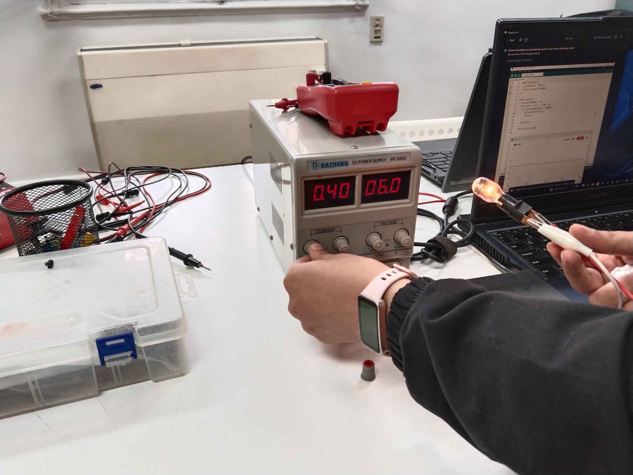
This week was about output devices and our group assignment was to measure the power consumption of an output device so we used the power supply and multimeter to do our measurements.
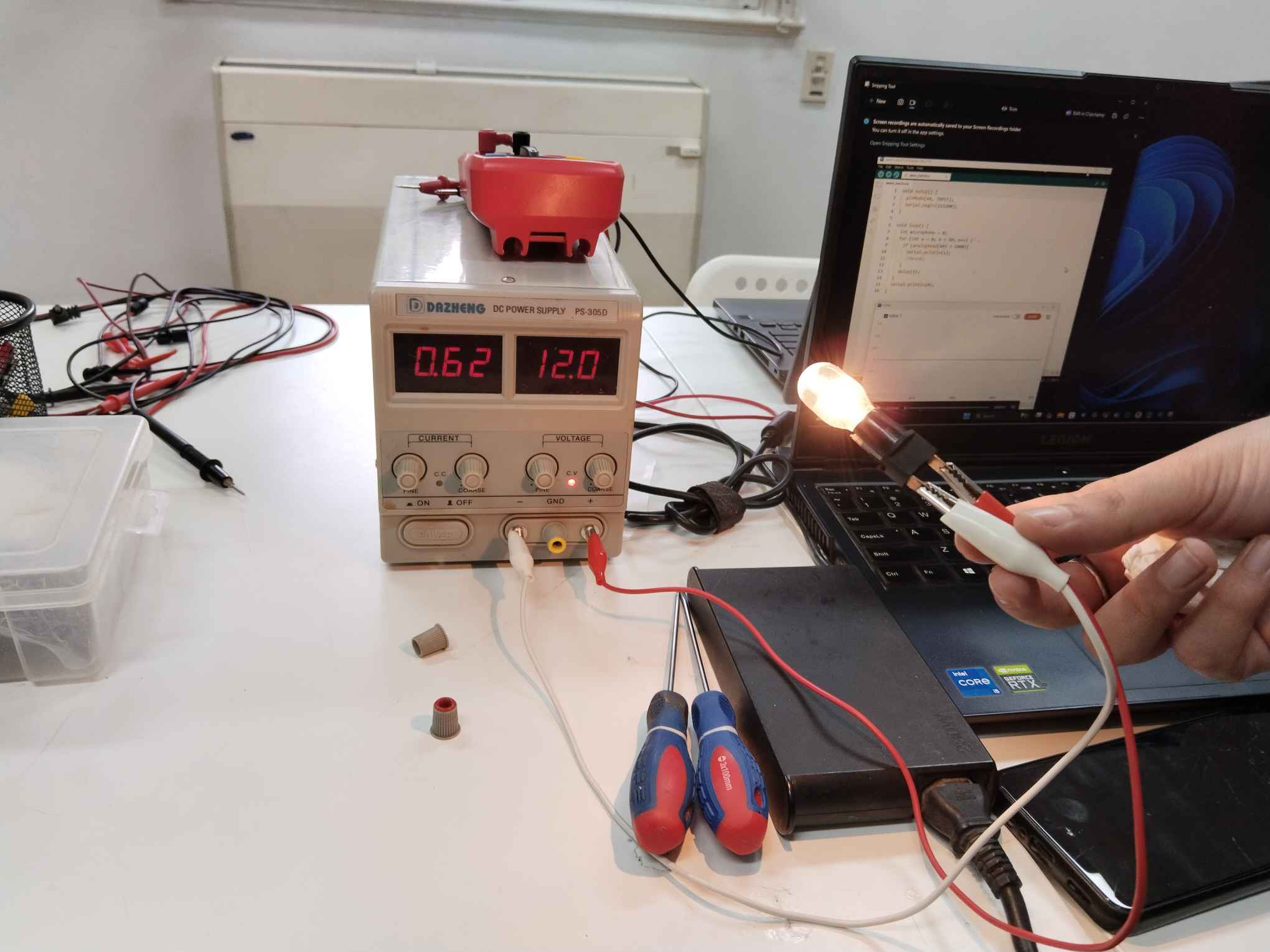
Measuring the power consumption is done by the famous law P=IV where P is power, I is the current, and V is the voltage. Using the Power supply we started giving the bulb a voltage of 6V and we saw that the bulb was not very bright. We increased the voltage to 12V and the bulb became much brighter. By substituting in the law P=0.62x12= 7.44 Watt. This tells us that the bulb's power consumption is about 7.44 Watt.
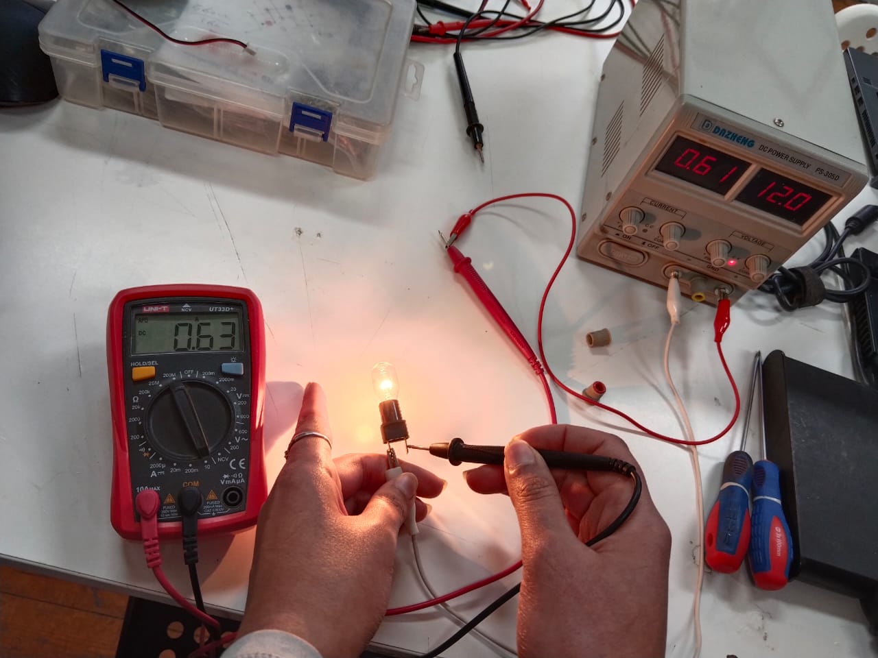
To measure the current running in the circuit and compare the results we put the multimeter in series with the bulb. We saw that there's about 0.02 A more in the multimeter. We think it's because of the resistance in the wiring.
2) Individual Assignment:
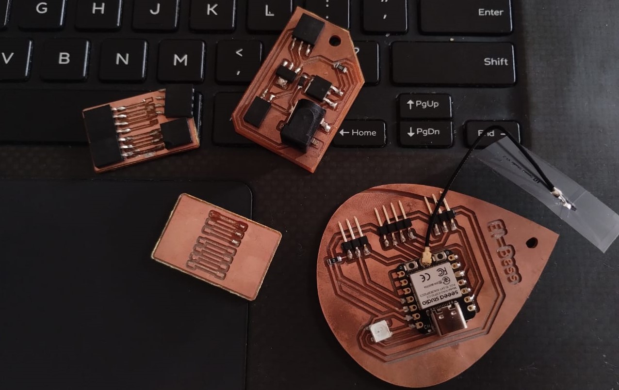
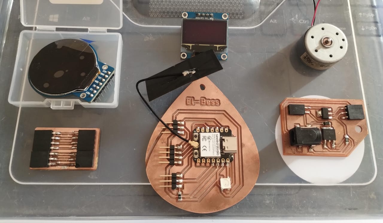
For my individual assignment I wanted my hero shot to be my failed and non-failed PCBs as this week was really rough. Everything stopped working or didn't even start working, no google search worked, not asking someone, even ai couldn't help. So, there's still a alot of debugging coming ahead but at least one of the devices worked.
1. OLED:
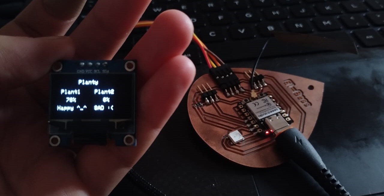
My last output device i tried but first to document was the OLED, I had my PCB designed and fabricated previously in Week 8 but I didn't test the I2C pins so I wanted to make sure the oled worked fine on the Planty PCB. I used the code I made earlier in Week 4 to make the test and it worked well.
#include < Ticker.h>
#include < SPI.h>
#include < Wire.h>
#include < Adafruit_GFX.h>
#include < Adafruit_SSD1306.h>

Ticker MoistTicker;


#define SCREEN_WIDTH 128  // OLED display width, in pixels
#define SCREEN_HEIGHT 64  // OLED display height, in pixels


// Declaration for SSD1306 display connected using I2C
#define OLED_RESET -1  // Reset pin
#define SCREEN_ADDRESS 0x3C
Adafruit_SSD1306 display(SCREEN_WIDTH, SCREEN_HEIGHT, &Wire, OLED_RESET);


int moistRead;
const int sensor_pin = D2;


void ReadMoistSensorOne() {
	moistRead = analogRead(sensor_pin);
	moistRead = map(moistRead, 3620, 1680, 0, 100);
	Serial.println(moistRead);
}


void setup() {
	// Set up Serial Monitor
	Serial.begin(115200);
	if (!display.begin(SSD1306_SWITCHCAPVCC, SCREEN_ADDRESS)) {
	Serial.println(F("SSD1306 allocation failed"));
	for (;;)
		;  // Don't proceed, loop forever
	}
	display.clearDisplay();
	MoistTicker.attach(3, ReadMoistSensorOne);
	pinMode(sensor_pin, INPUT);
}

void loop() {
	// Main structure
	display.setTextSize(1);
	display.setTextColor(WHITE);
	display.setCursor(40, 2);
	display.println("Planty");
	display.display();

	display.setTextSize(1);
	display.setTextColor(WHITE);
	display.setCursor(2, 20);
	display.println(" Plant1");
	display.display();

	display.setTextSize(1);
	display.setTextColor(WHITE);
	display.setCursor(70, 20);
	display.println("Plant2");
	display.display();


	//Plant 1 Readings
	if (moistRead > 40) {
	display.setTextSize(1);
	display.setTextColor(WHITE, BLACK);
	display.setCursor(12, 35);
	if (moistRead < 100) display.print(" ");
	if (moistRead < 10) display.print(" ");
	display.print(moistRead);
	display.print("%");
	display.display();

	display.setTextSize(1);
	display.setTextColor(WHITE, BLACK);
	display.setCursor(2, 50);
	display.println("Happy ^_^");
	display.display();

	} else {
	display.setTextSize(1);
	display.setTextColor(WHITE, BLACK);
	display.setCursor(12, 35);
	if (moistRead < 100) display.print(" ");
	if (moistRead < 10) display.print(" ");
	display.print(moistRead);
	display.print("%");
	display.display();

	display.setTextSize(1);
	display.setTextColor(WHITE, BLACK);
	display.setCursor(2, 50);
	display.println("SAD :(   ");
	display.display();
	}
	delay(1000);
}
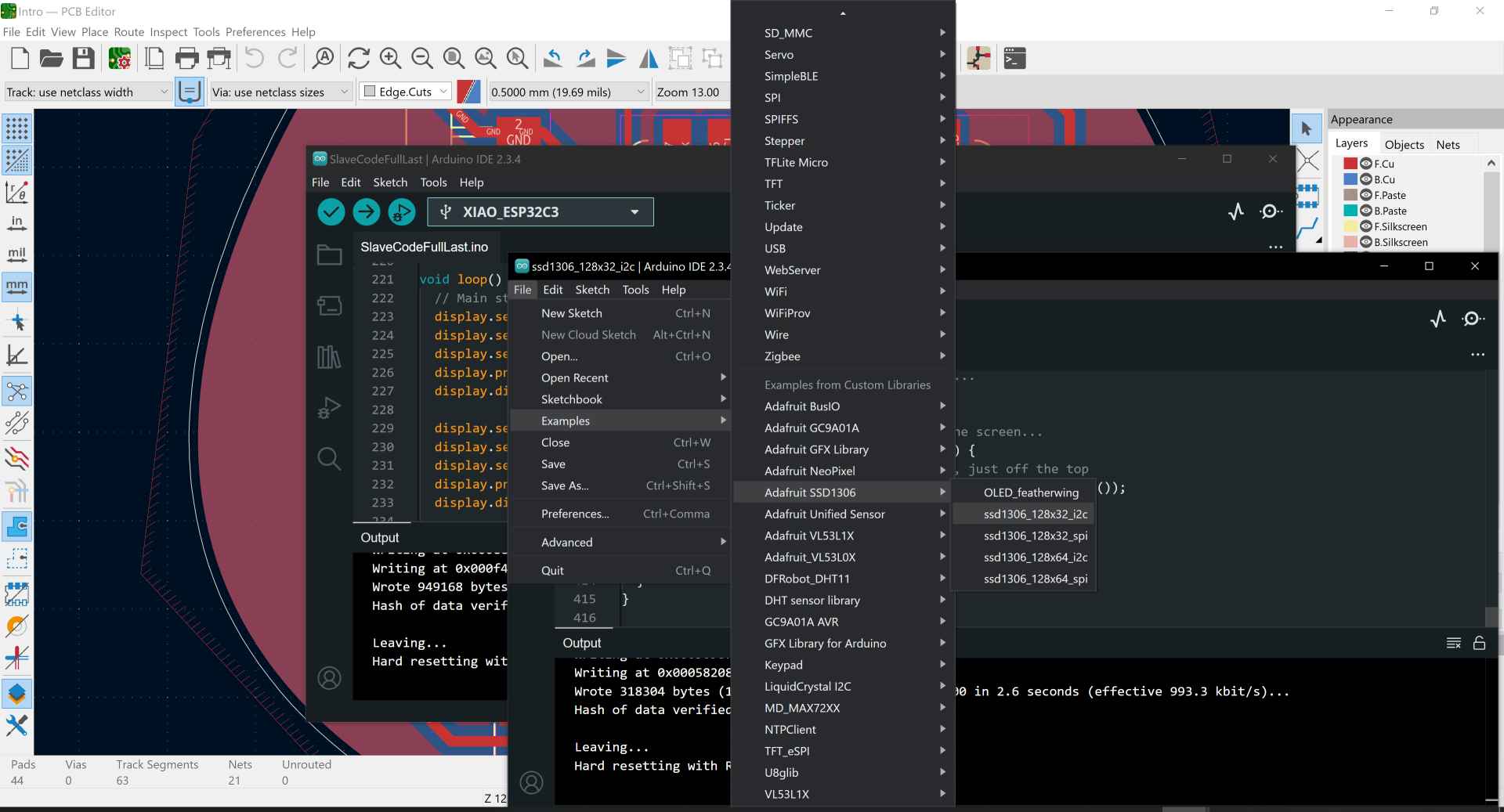
I also used the example code for this OLED to test its limits and know what I can do with it.
This was the happy part of the story but the first time I wired the OLED it didn't work, even the backlight didn't work like there were no power or the OLED broke. I made sure all my wiring are connected correctly. Then I went to the multimeter, turned to measure the volt and measured the volt coming out from the microcontroller and it was around 3.3v then I measured the volt on the pin headers and the volt was the same. At last I measured it on the OLED itself and the multimeter showed 2.6v, so I thought there was something wrong with the jumper wires I'm using. I changed the wires with new ones and yeah, it wooooorked.
2. 1.28 tft GC9A01:
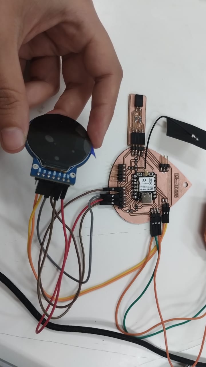
After lots of only backlight working and not anything else. I asked for my instructor Saeed's help. All this was about was just a matter of wiring. This display is very tricky in it's wiring as at first I thought it was I2C because it had SDA and SCL. Then I discovered it was SPI but there wasn't a good guide for how to wire it so I wasn't sure if my wiring was correct though I tried different wirings and followed different tutorials.
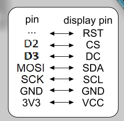
This is the right wiring for the display with the Xiao ESP32-C3. It doesn't need a MISO pin, only MOSI, SCK, 2 other pins for the CS and DC, and the RST is not needed.
At first I made a PCB design for the display to connect it to my board. This PCB was lots of pain and losses as a 0.3 endmill broke while fabricating it. I fabricated it 4 times and each one of them failed in a different way. Even the last one that survived till stuffing while testing the display, the pin sockets was removed with the traces.
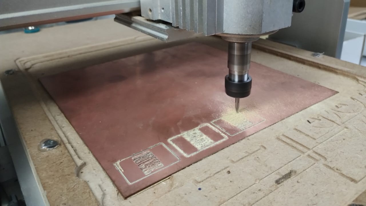
The first one the sheet moved while milling so this made the endmill to break and as it was too small I didn't even notice it was broken. I just tried to hold the sheet again and refabricate it. Now you know why the second trial failed too. 😭
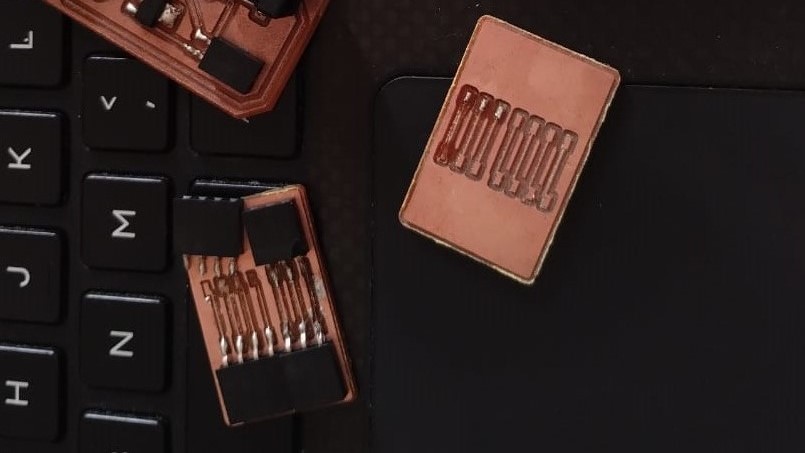
In the next 2 trials I used the 0.4 V-Bit. The traces were clean but toooooooo thin so I wasn't even sure they worked. They did work... but just for a short period of time as the traces were removed first while soldering and the next while testing.
Because of this I'll not be covering this PCB and I'm working on another PCB which is the upgrade of the Planty PCB to have all pins of the xiao out.
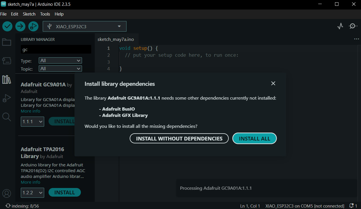
Till we get to the part when I fabricate the new full pins PCB install the Adafruit GC9A01 Library.
-----------------------------------------------------------------------------------------------------------------
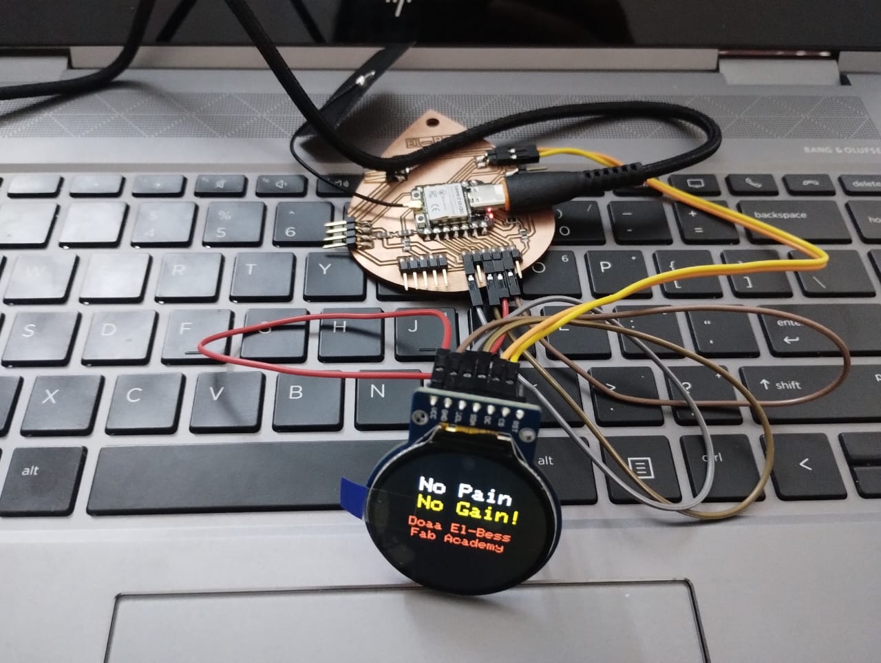
After fabricating the new version of Planty PCB which I mentioned in Week 8 I wired the display to it using the wiring that Saeed provided me with. For testing the posibilities of the display I used the example code of the Adafruit-GC9A01 library and here are the results.
Then I wanted to go further and try to write myself on the screen so I edited on the example code and wrote my own words. I chose to write "no pain, no gain" as this result came after lots of work and failures. So does lots of things in life.
This is the code after editing. I removed most of the actions that the display do and changed in the testText void as I made it to write different words with different colors and sizes and set cursor where I wanted the words to be.
To declare the problem I had initializing the display more, Saeed explained to me that the first lines in the code after "#if defined(ARDUINO_SEEED_XIAO_RP2040)" will be neglected as I'm not using a Xiao RP2040. So I have to define the pins after the #else.
#include "SPI.h"
#include "Adafruit_GFX.h"
#include "Adafruit_GC9A01A.h"

// Define pins for display interface. You'll probably need to edit this for
// your own needs:

#if defined(ARDUINO_SEEED_XIAO_RP2040)

// Pinout when using Seed Round Display for XIAO in combination with
// Seeed XIAO RP2040. Other (non-RP2040) XIAO boards, any Adafruit Qt Py
// boards, and other GC9A01A display breakouts will require different pins.
#define TFT_CS D2 // Chip select
#define TFT_DC D3 // Data/command
#define TFT_BL D6 // Backlight control

#else // ALL OTHER BOARDS - EDIT AS NEEDED

// Other RP2040-based boards might not have "D" pin defines as shown above
// and will use GPIO bit numbers. On non-RP2040 boards, you can usually use
// pin numbers silkscreened on the board.
#define TFT_DC  D3
#define TFT_CS D2
// If display breakout has a backlight control pin, that can be defined here
// as TFT_BL. On some breakouts it's not needed, backlight is always on.

#endif

// Display constructor for primary hardware SPI connection -- the specific
// pins used for writing to the display are unique to each board and are not
// negotiable. "Soft" SPI (using any pins) is an option but performance is
// reduced; it's rarely used, see header file for syntax if needed.
Adafruit_GC9A01A tft(TFT_CS, TFT_DC);

void setup() {
  Serial.begin(115200);
  Serial.println("GC9A01A Test!");

  tft.begin();

#if defined(TFT_BL)
  pinMode(TFT_BL, OUTPUT);
  digitalWrite(TFT_BL, HIGH); // Backlight on
#endif // end TFT_BL

}

void loop(void) {
  for(uint8_t rotation=0; rotation< 4; rotation++) {
    tft.setRotation(rotation);
    testText();
    delay(2000);
  }
}


unsigned long testText() {
  tft.fillScreen(GC9A01A_BLACK);
  unsigned long start = micros();
  tft.setCursor(60, 50);
  tft.setTextColor(GC9A01A_WHITE);  tft.setTextSize(3);
  tft.println("No Pain");
  tft.setCursor(60, 80);
  tft.setTextColor(GC9A01A_YELLOW); tft.setTextSize(3);
  tft.println("No Gain!");
  tft.setCursor(50, 120);
  tft.setTextColor(GC9A01A_RED); tft.setTextSize(2);
  tft.println("Doaa El-Bess");
  tft.setCursor(55, 140);
  tft.println("Fab Academy");


  return micros() - start;
}
3. N-Channel Mosfet:
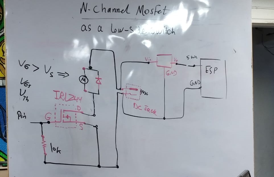
Our instructor Saeed started by talking with us about different transistors then took us deeper with the N-Channel Mosfet which is a type of FET transistors. By using the mosfet you can control any component on/off by connecting the mosfet's gate to a pin on the microcontroller.
After talking about types of transistors and going through the wiring of all components and knowing we need to have a voltage regulator to convert the 12v that we need for the motor from the adapter to 5v for the xiao. We also need a diode to protect the circuit and make sure the current goes in the right way.
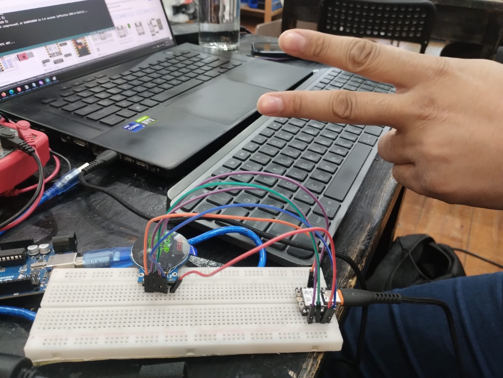
We tested the circuit first using a breadboard and TH components with a simple blink code.
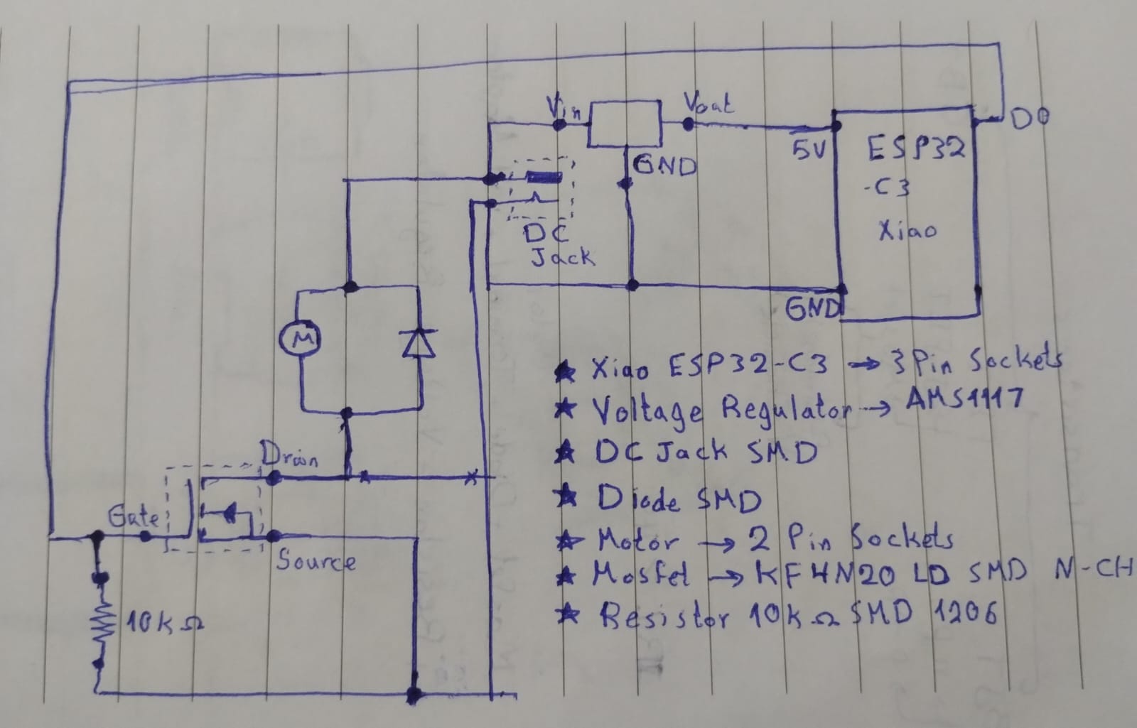
Here I was preparing for the schematics and defining the components I'll be using in the PCB.
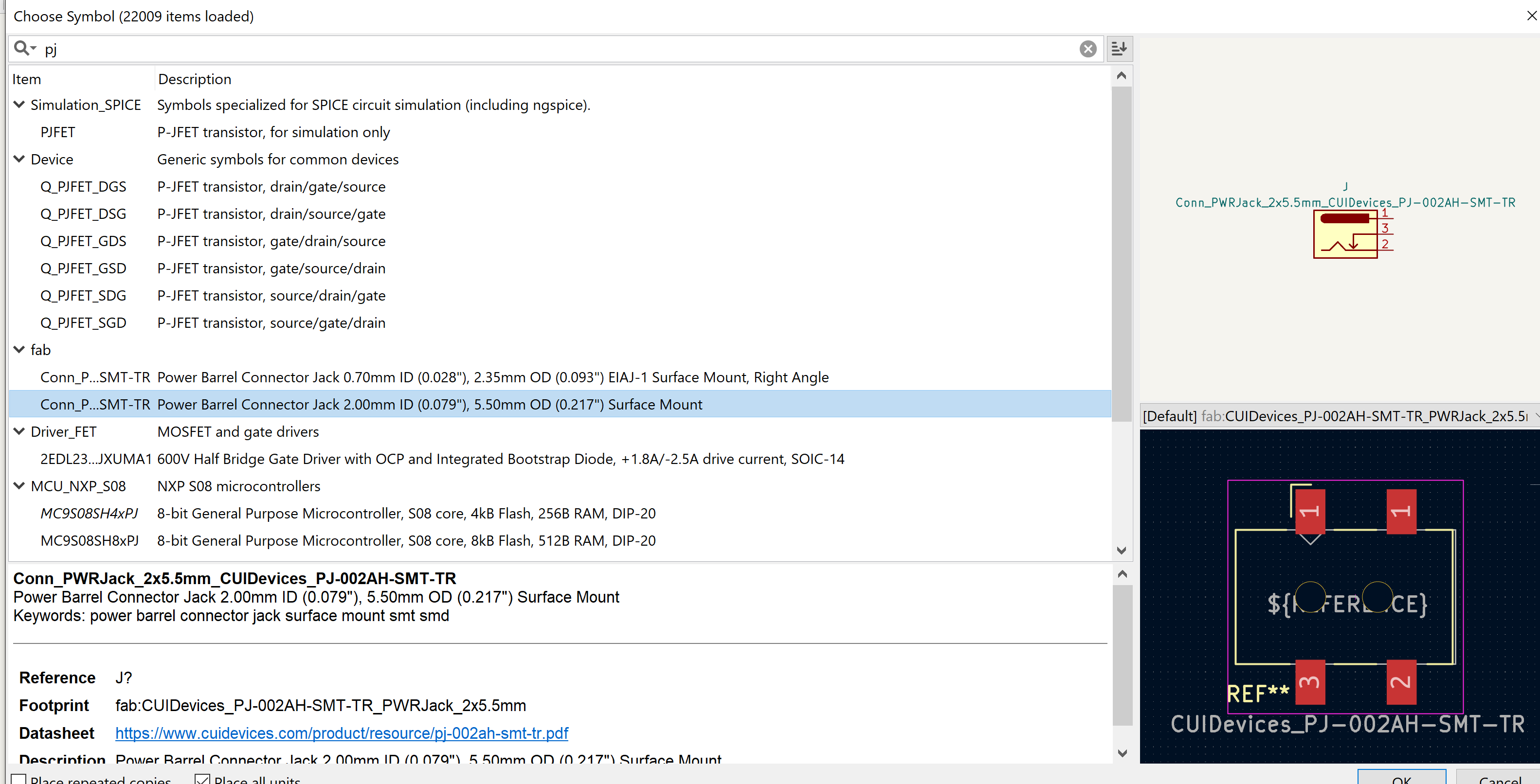
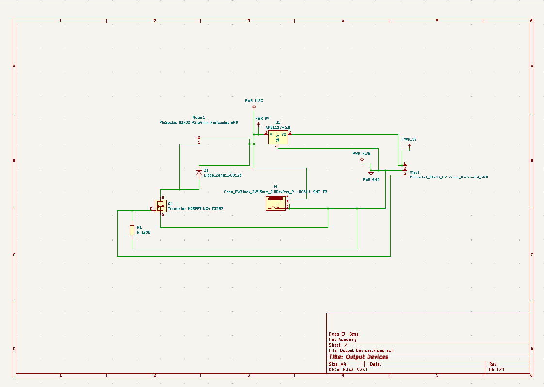
1- I worked on KiCAD to make the schematic and started by adding symbols. That was the closest symbol of DC Jack to the one I had.
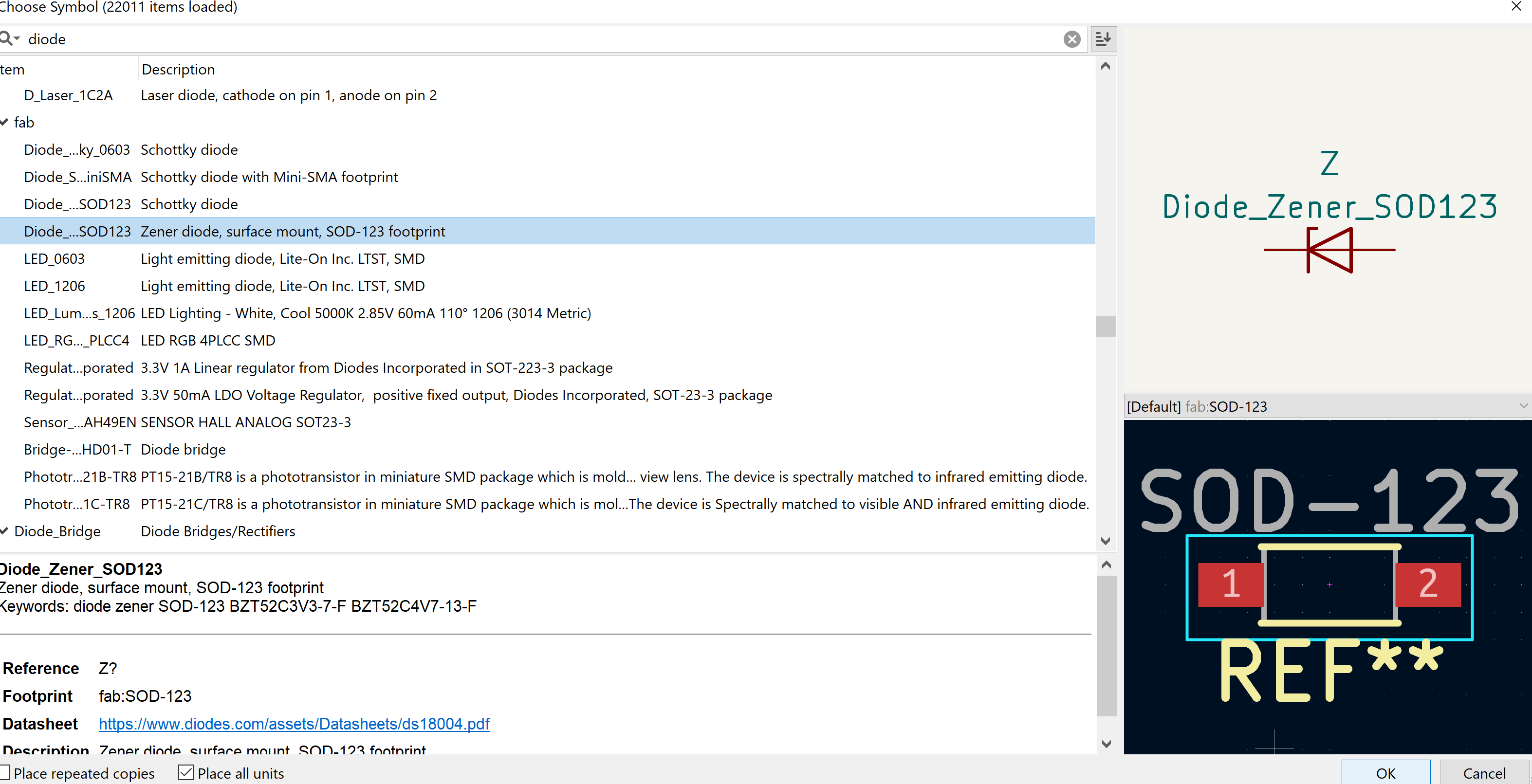
2- I searched a lot to try to know the best diode symbol and used this one but I could have used a SMD LED symbol better as it's the same size of the diode I had.
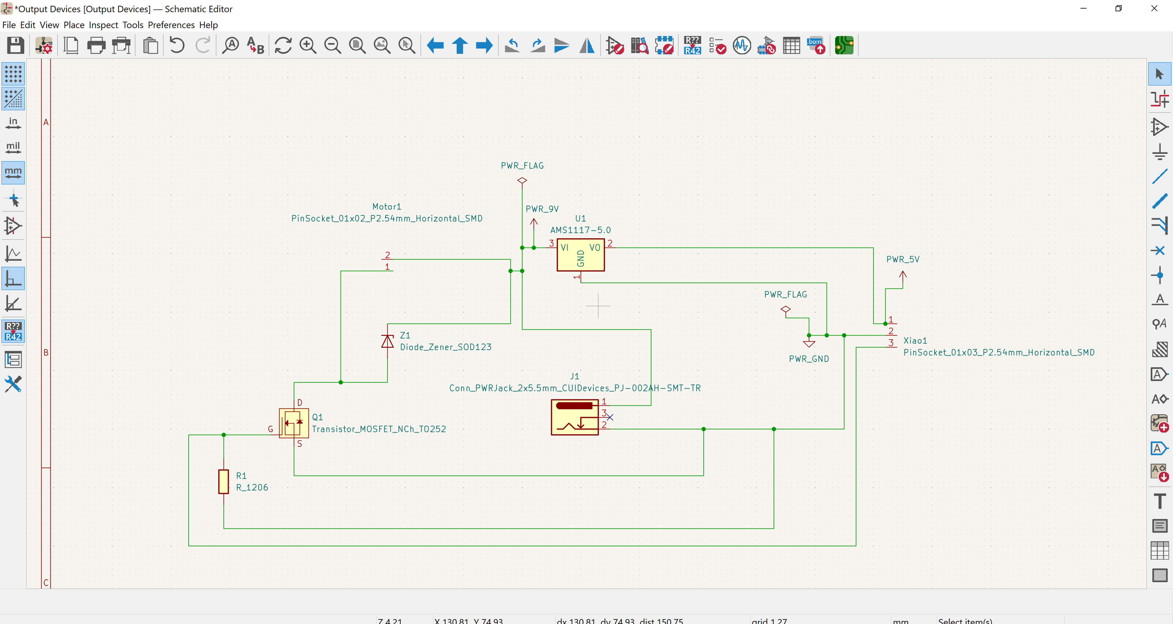
3- I then made my schematic and ran an ERC which went well.
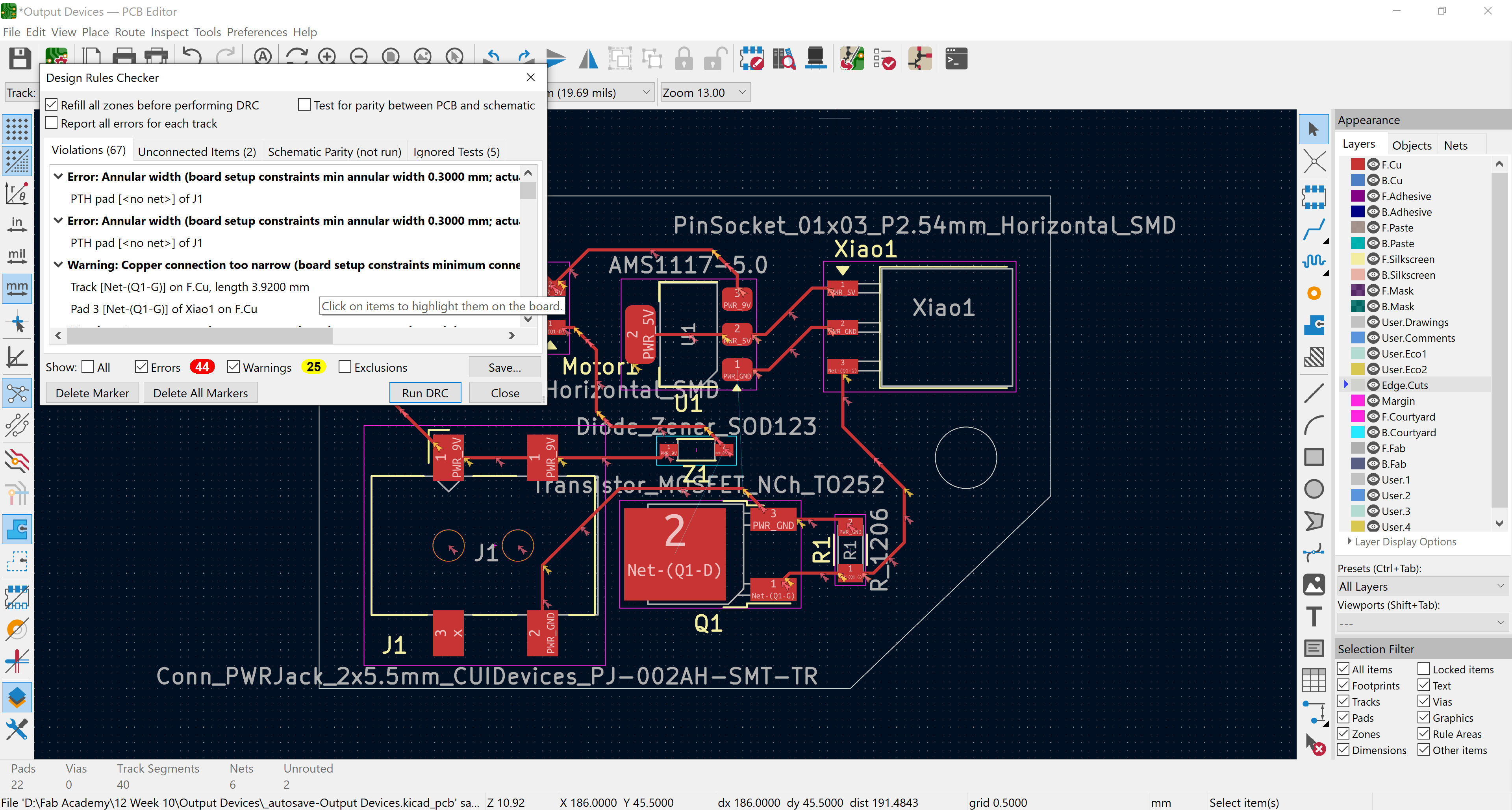
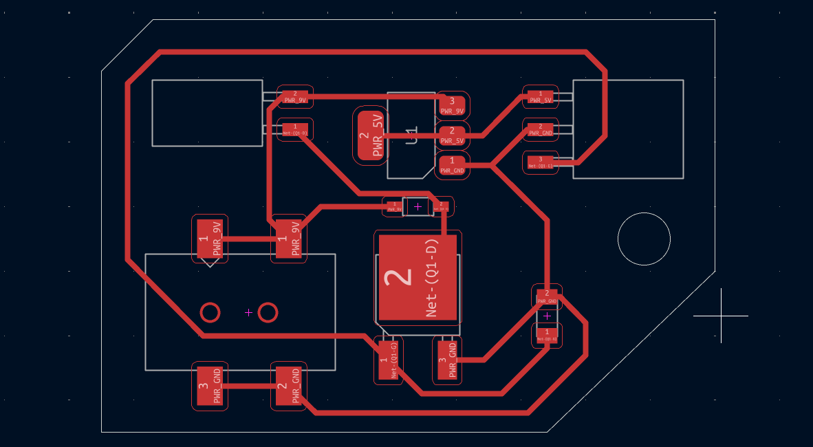
4- Moving to the PCB Editor I started routing but forgot to define the design rules first so when I ran the DRC I had so much errors.
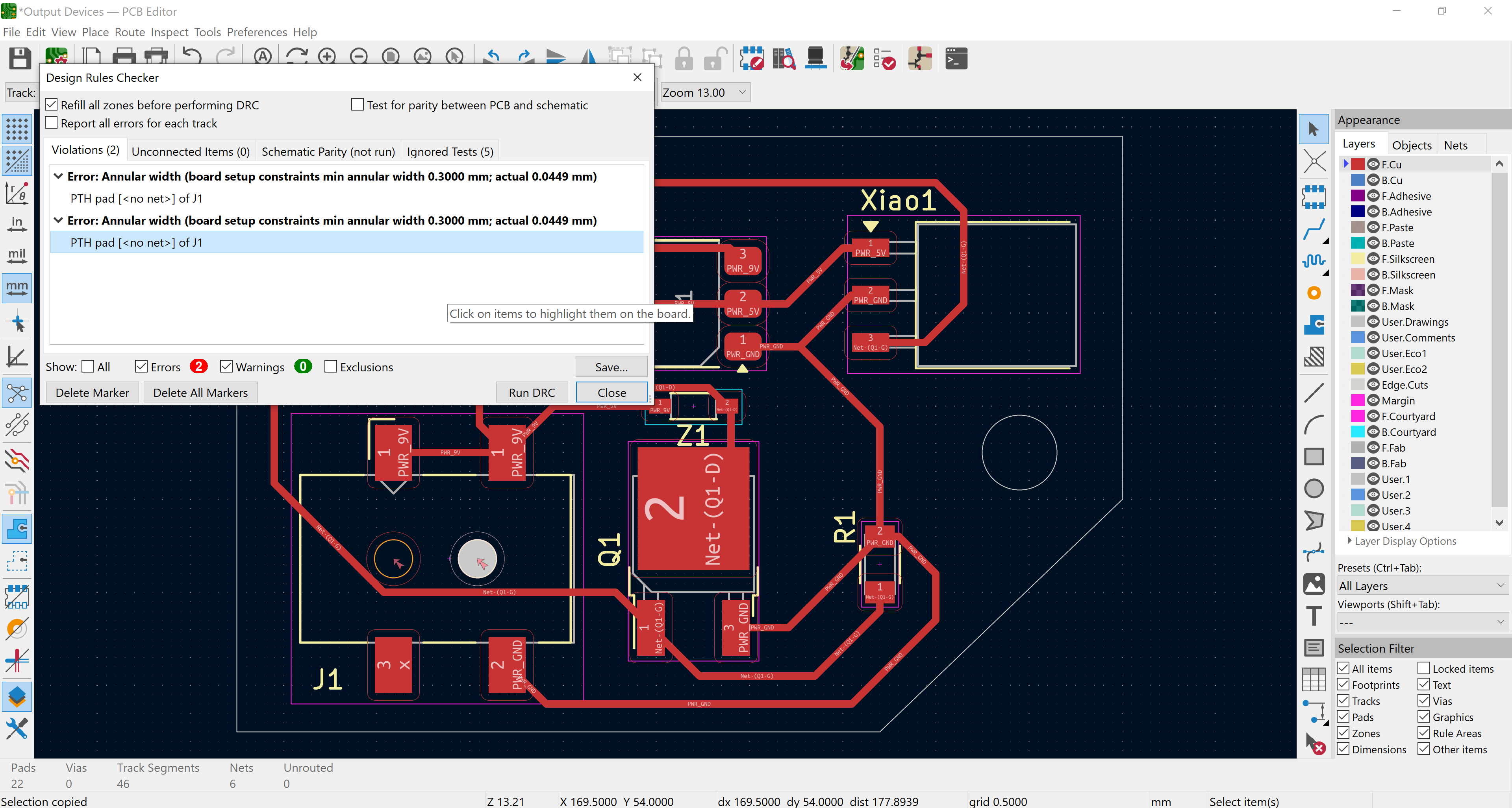
5- I went back and defined the design rules I knew previously from week 6 then ran another DRC and got that I have problems with the pads of the DC Jack.
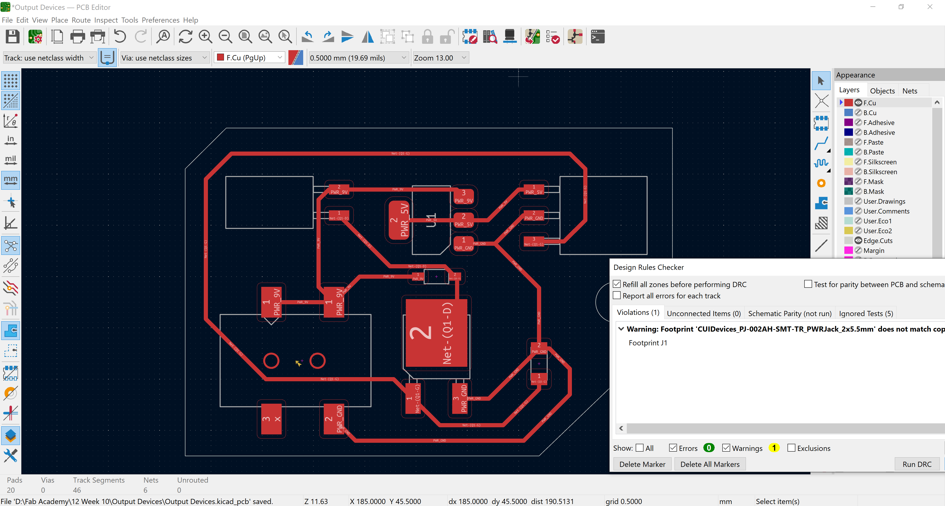
6- I drew circles as a F.Cu layer where the pads were and removed the pads from the footprint so I got a final warning that the footprint is changed but we can ignore this.
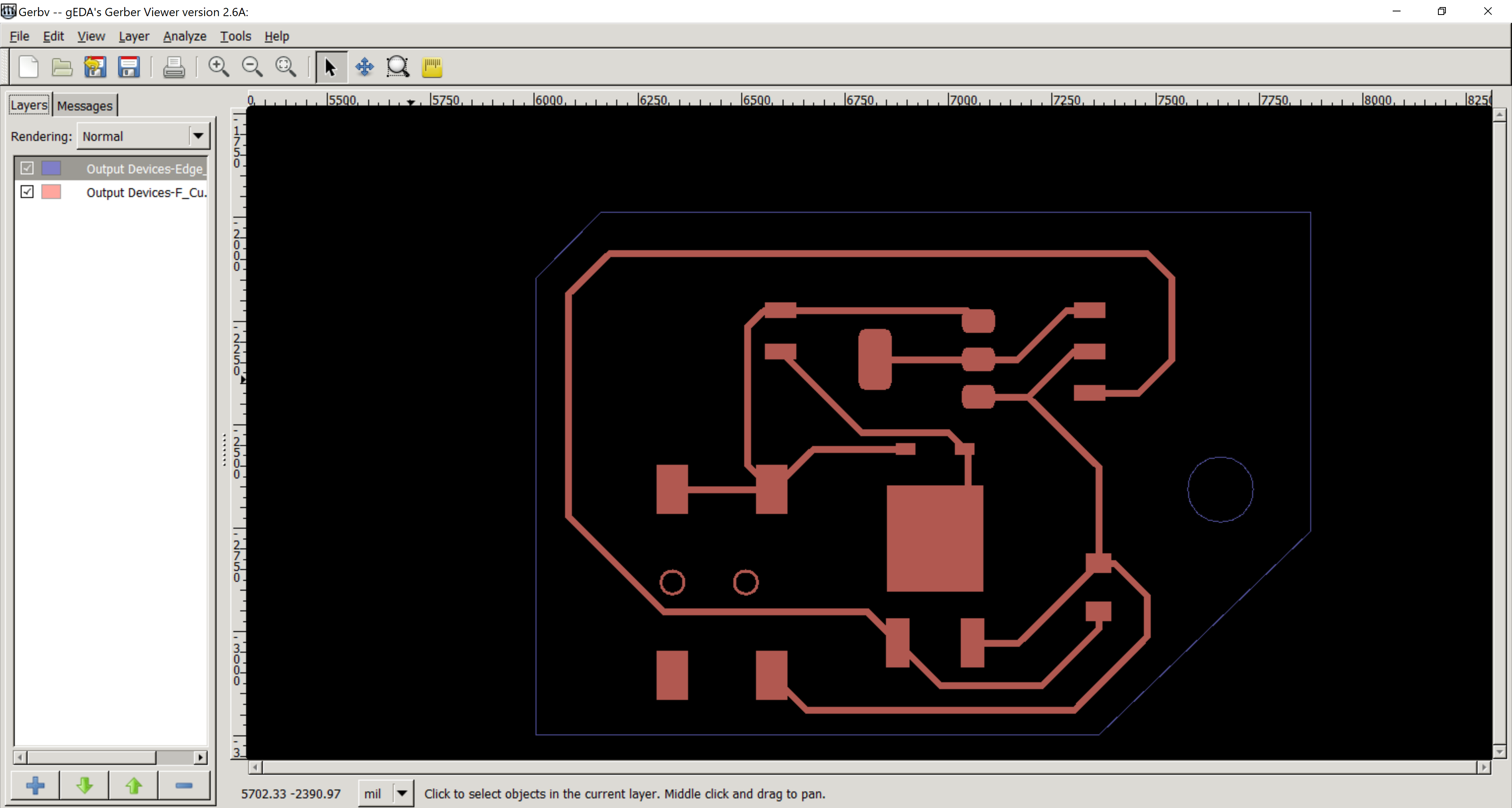
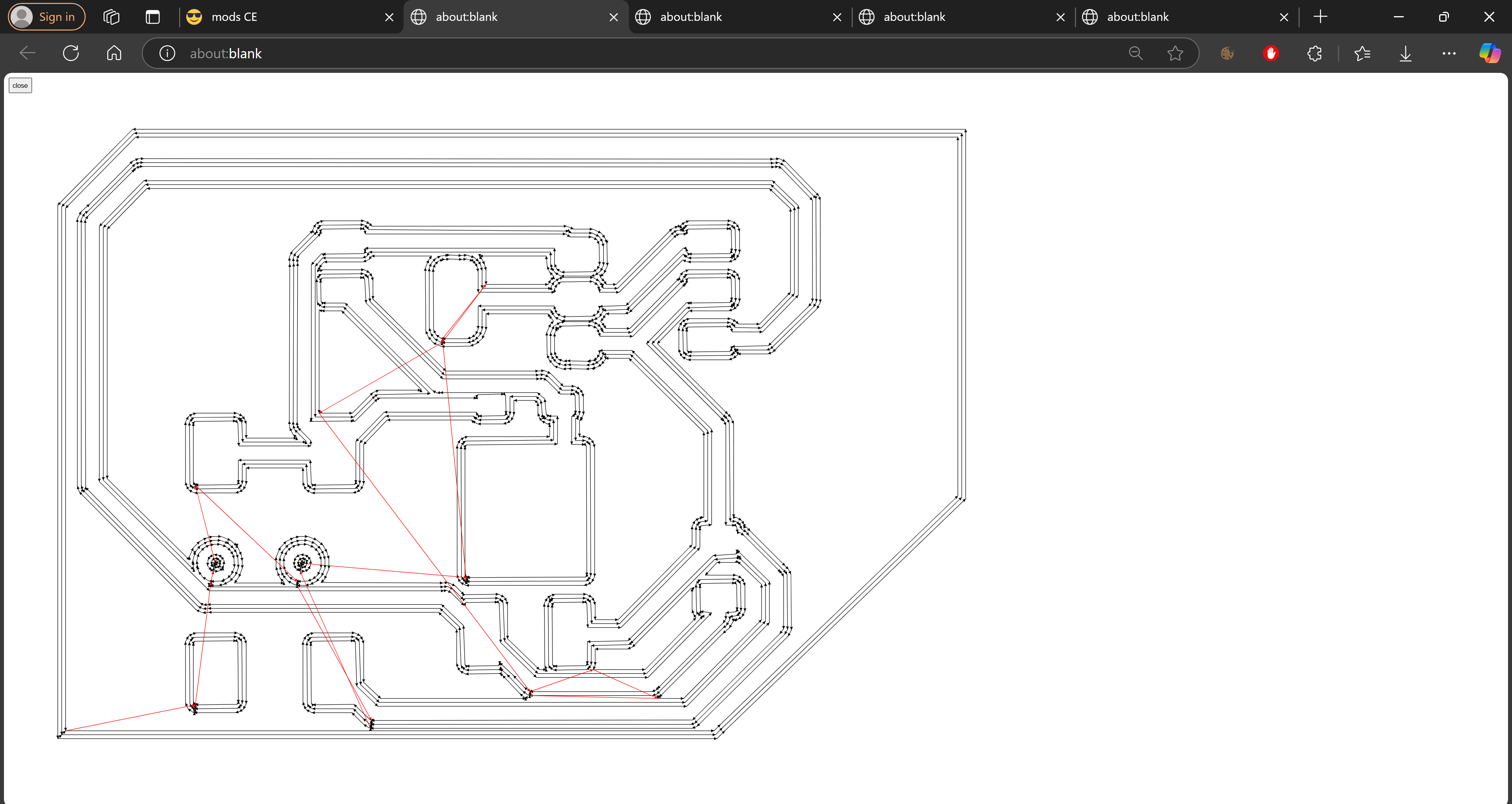
7- After exporting a gerber file of the traces and outline and another one for the drill and the las one for the outline I imported them to Gerbv and saved them as pdf files with black and white colors.
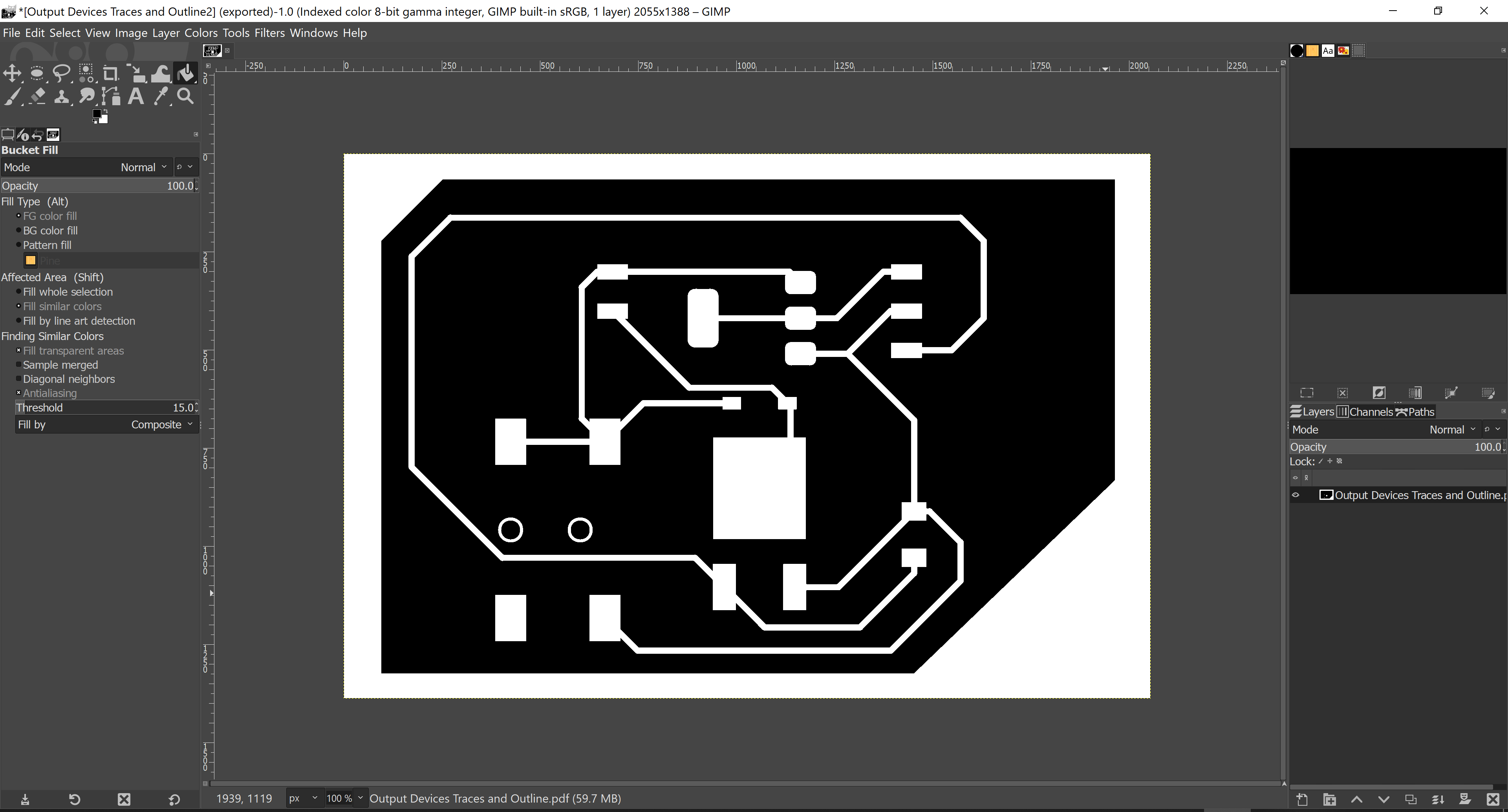
8- By importing the pdfs to GIMP and choosing indexed mode and choosing value invert in the traces pdf then saving each file separately as png.
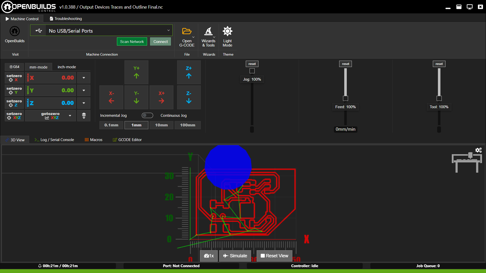
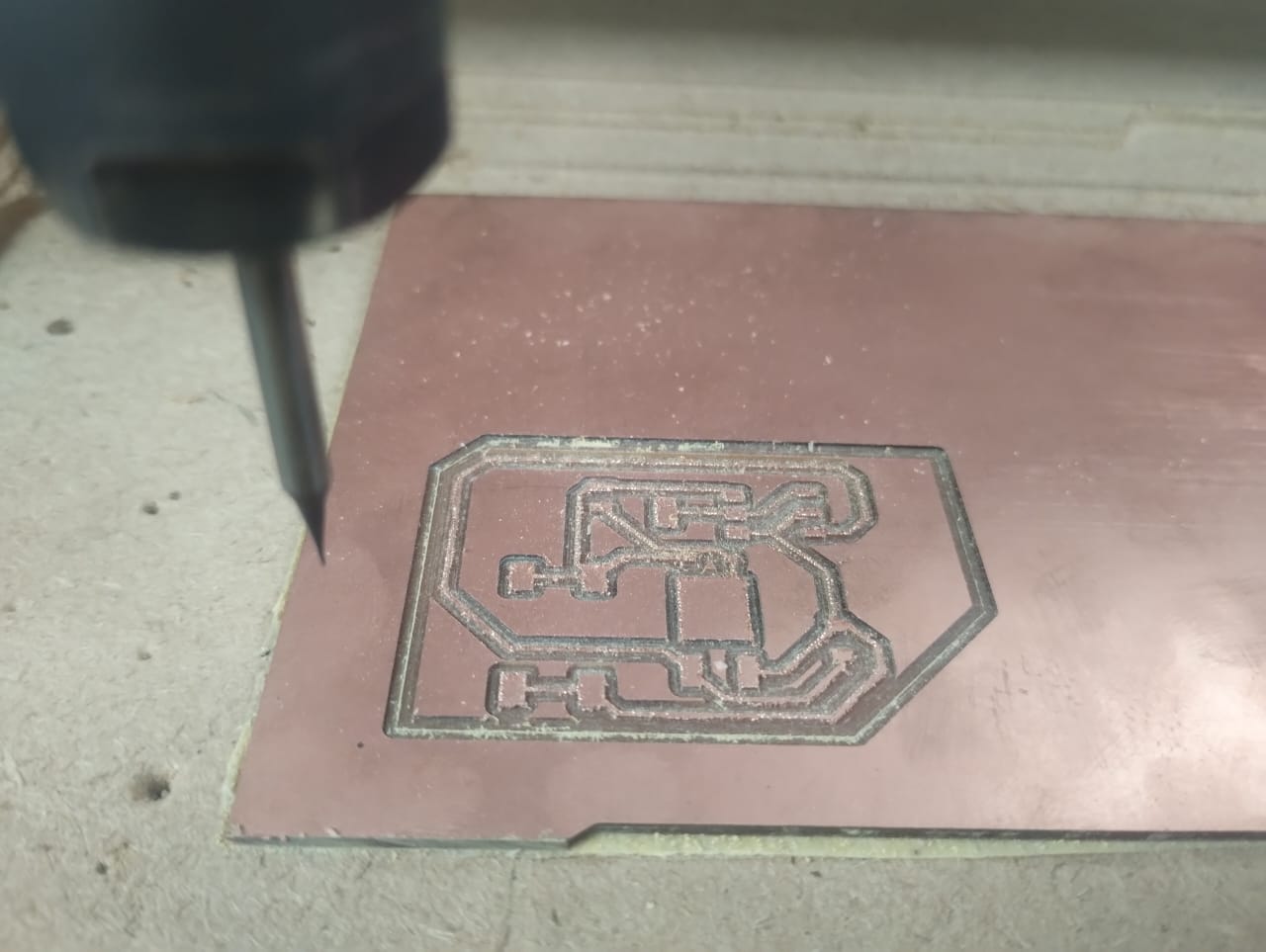
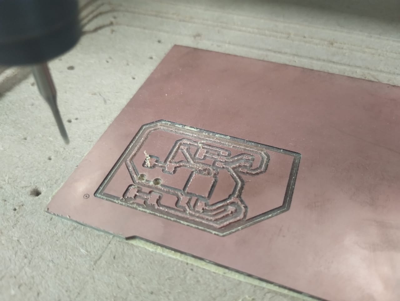
10- Opening the traces g-code file on openbuilds and starting with it with a 0.4mm endmill.
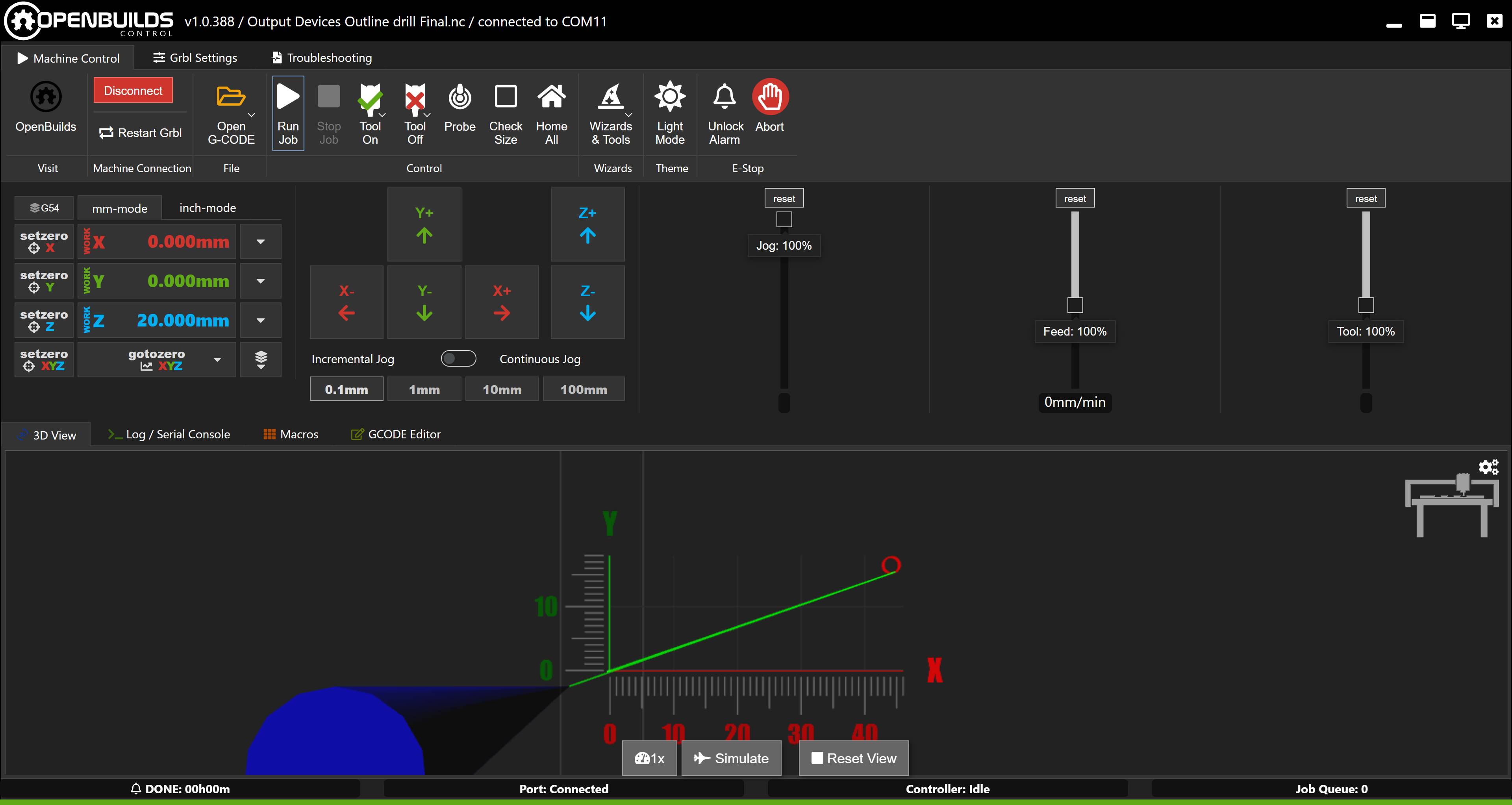
11- Making the drill using the 1.5mm endmill in a single file after the traces are done.
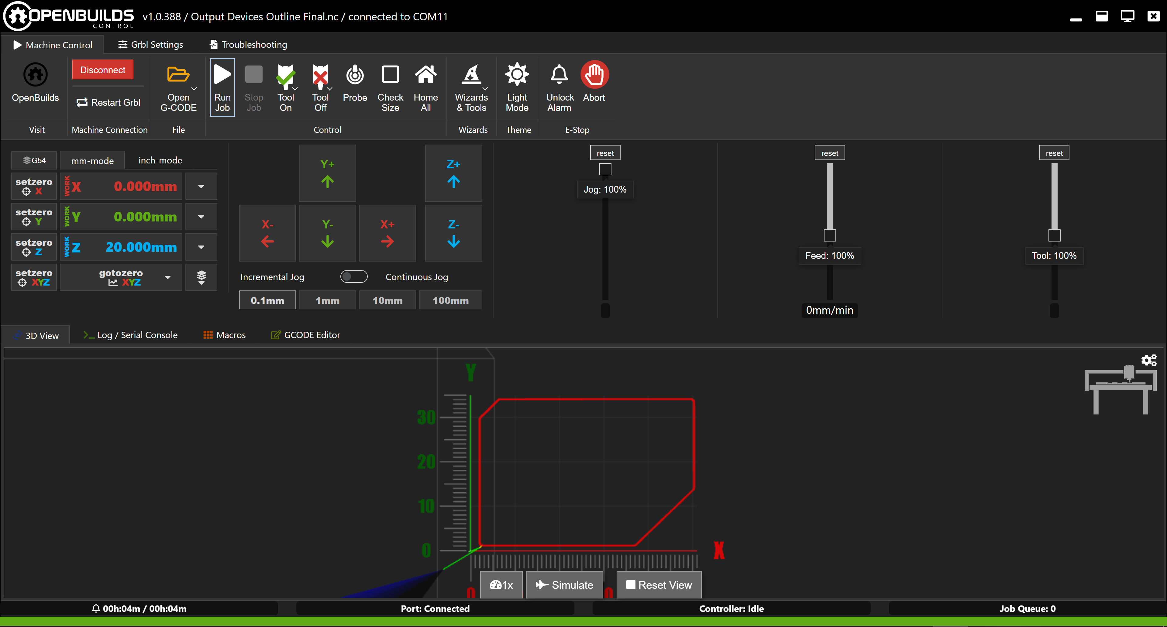
12- Finishing with the outline using the same 1.5mm endmill.
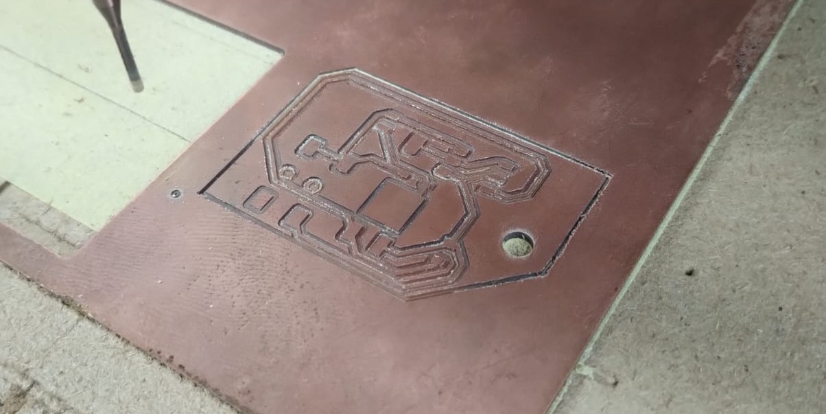
This was the result of the traces and the drill.
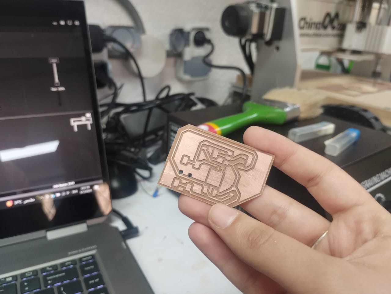
After milling the outline.
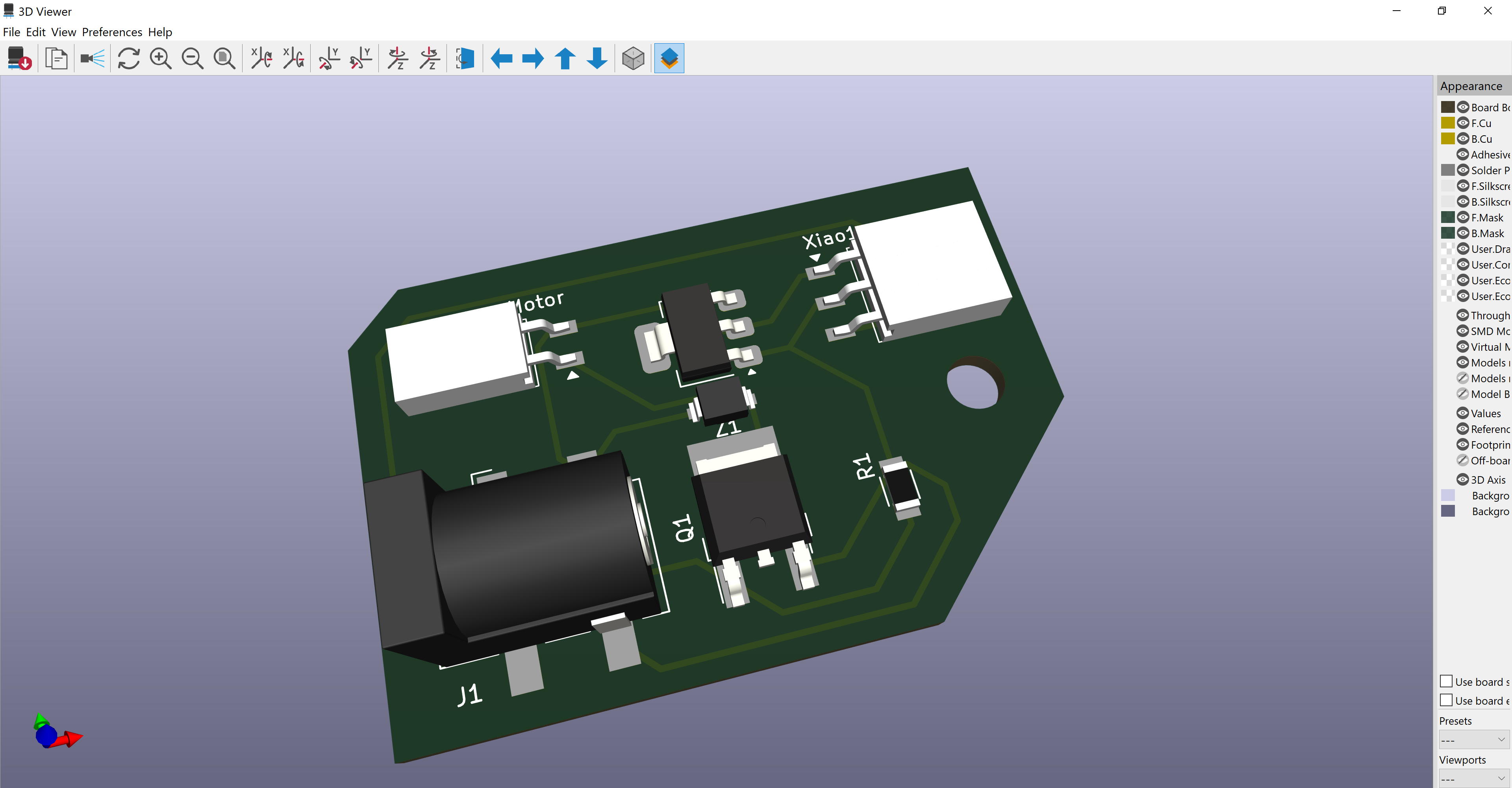
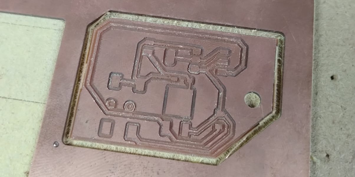
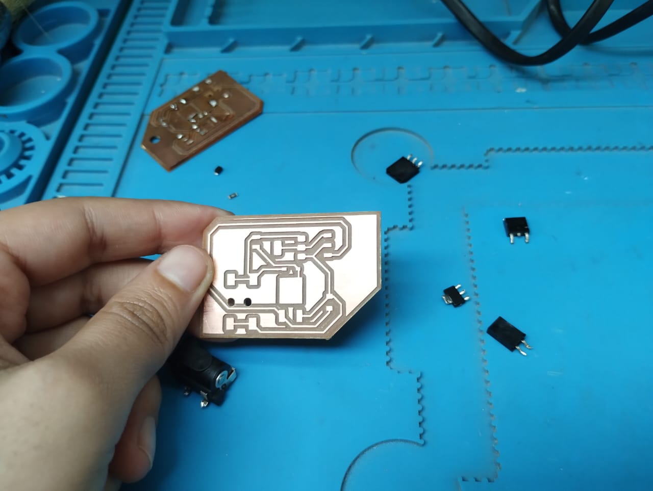
Final output of milling.
Here I was soldering and stuffing the PCB by using the solder paste for small components and soldering iron for other components.
When I tried to use the PCB and wire the components the motor didn't work. I used the multimeter to troubleshoot the problem and find out what was going wrong. I didn't manage to know the problem. I just found out that the DC Jack didn't have volt out on its pins though there were volt coming out from the adapter.
Asking Saeed he managed to know the problem and detected another one that I soldered the diode in the other direction. The main problem was that the 2 pins for the GND of the DC Jack were not connected. He told me to solder a small wire between them and test again.
It did actually work eventually and my next step will be refabricating the PCB with the 2 pins connected and shooting a hero video of it working.
-----------------------------------------------------------------------------------------------------------------
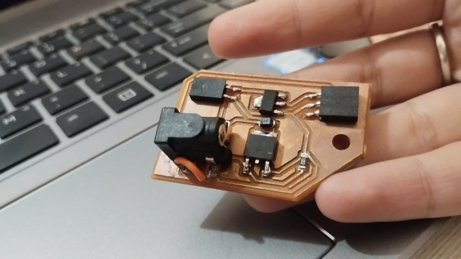
Finallyyyyyy, I got my PCB refabricated after solving the problem in the design.
1- I made a small edit on the schematic and connected the 2 and 3 pins of the DC Jack together.
2- After updating the PCB from schematic I routed the 2 pads together.
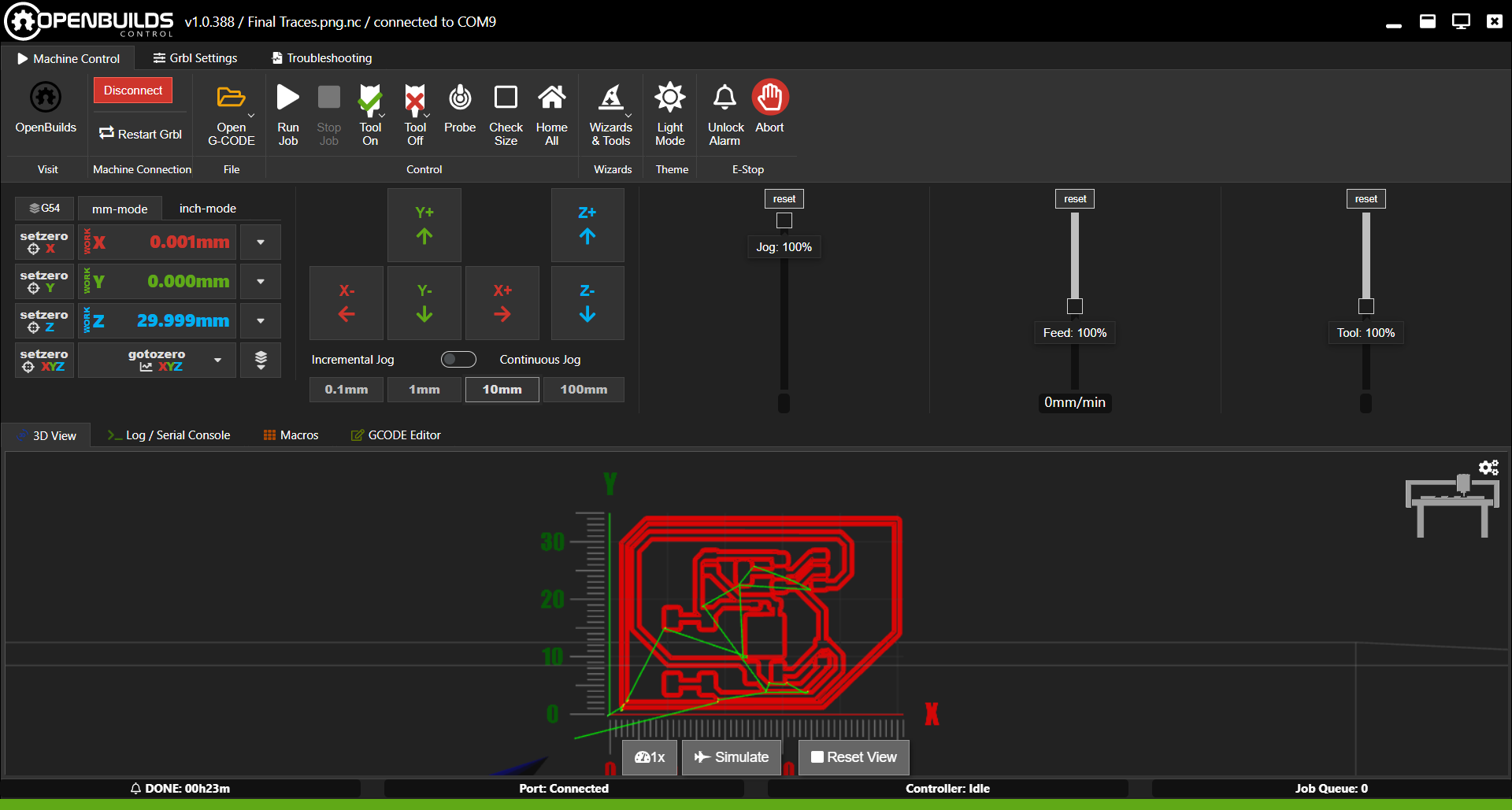
3- I went through all the process again of preparing for fabrication till I got to openbuilds and started milling the PCB.
Traces with 0.4mm endmill.
Drills with 1.5mm endmill. Then outline.
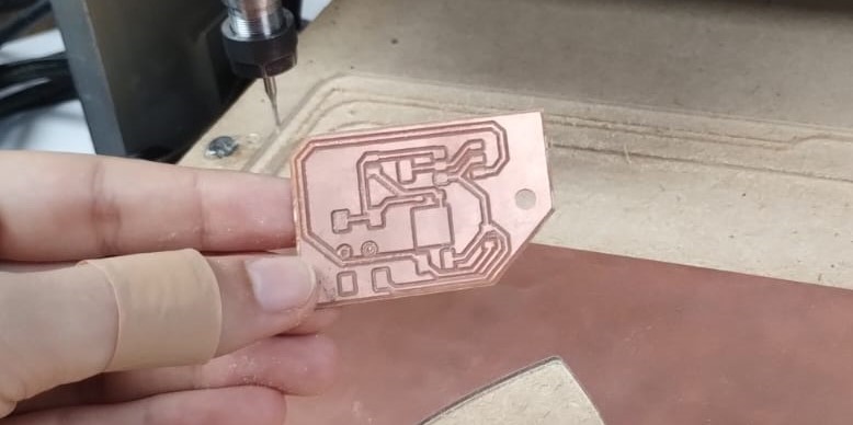
A nice looking PCB after some sanding.
I desoldered the components from the old PCB and started soldering them again on the new one.
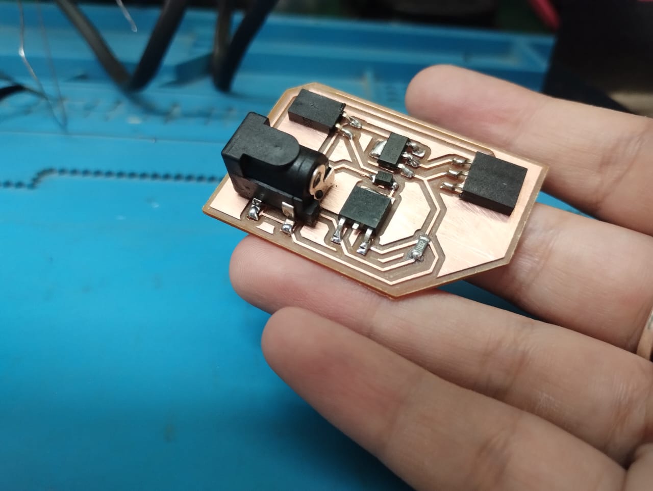
Final look of the PCB.. 🥳