
Input Devices
Here's a summary about what you'll see next:
- 1) Group Assignment
- 2) Individual Assignment:
-
- Step Response --> Water Level Sensing
- Magnetic Control Switch
- 3) Original Files
1) Group Assignment:
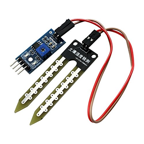
Soil Moisture Sensor
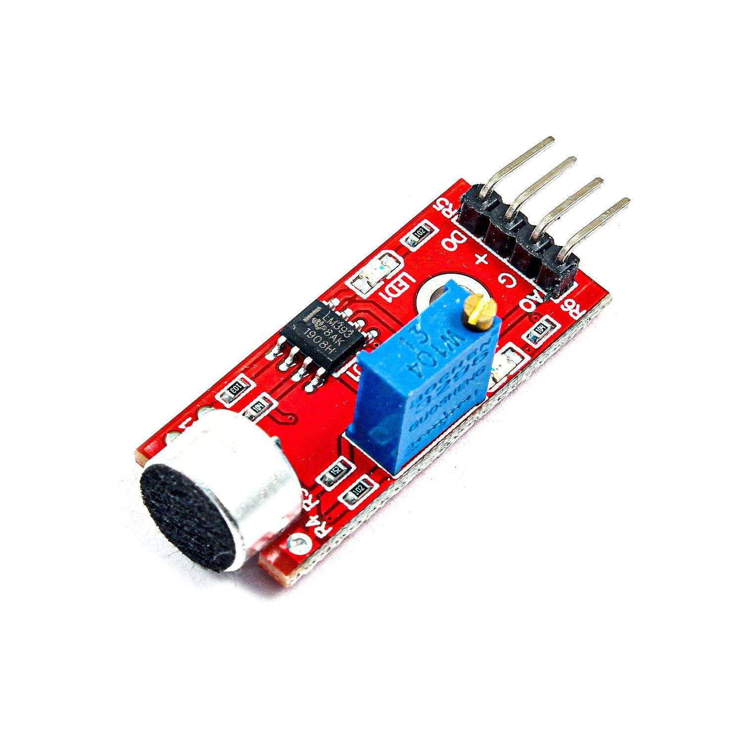
Microphone Sensor
For this week group assignment we went through different sensors or input devices and learned the idea of probing sensors to get the best results from them.
We tested out the michrophone sensor and the soil moisture sensor and viewed the serial plotter to see what's happening with the signals and what do the sensors read.
2) Individual Assignment:
This week we had a lot of fun work exploring different sensors and new ways "to me" to measure things. I explored 3 sensors, 2 worked great and one didn't which was the TOF sensor. So, let's start with the one related to my final project and walk through the process of making it work.
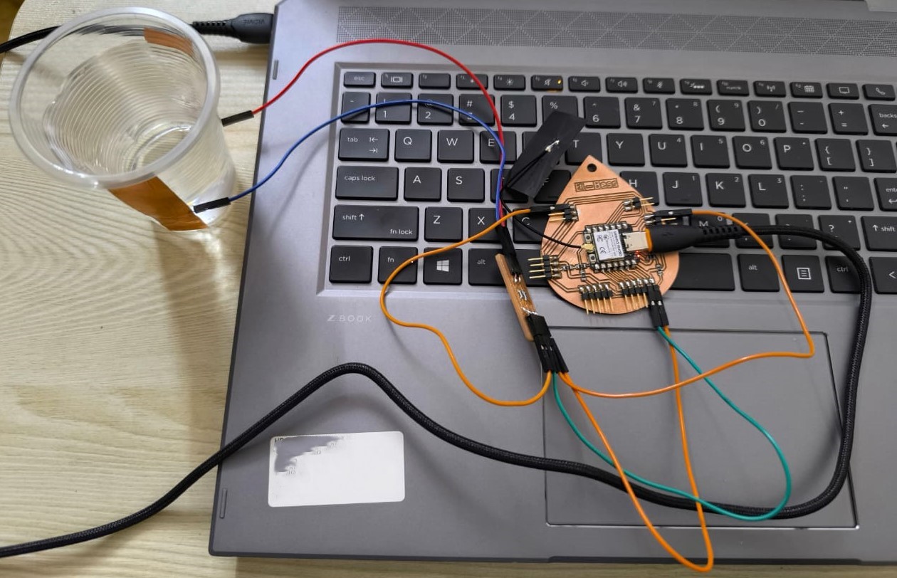
1. Step Response --> Water Level Sensing:
There are steps I walk through to make any PCB and test it out with the devices. First, I read the sensor's datasheet and search about it using google and see examples of it. After understanding the sensor I start making the schematic and define the wiring. Then Design the PCB by making traces and prepare gerber files for fabrication. After that I fabricate the PCB using CNC Milling Machine then I Solder the fabricated PCB and stuff the components. Finally, I finish my wiring and program the microcontroller to test what I need.
Step 1: Understand Step Response:
Here's the link where I started my journey exploring step response and how it works. There are several ways to use the step response but in my case I'll use it as a water level sensor. We use 2 copper electrodes, one attached to the tx pin (Here I'm using A0) and the other is receiving on D1. Imagine waves being sent from tx electrode to the rx electrode and there is something between them. For sure the value that we receive will change based on the change in stuff "water". Also there will be so much noise in this circuit so we overcome this by having biiig resistors on the GND and VCC.
Step 2: Schematic and Wiring:
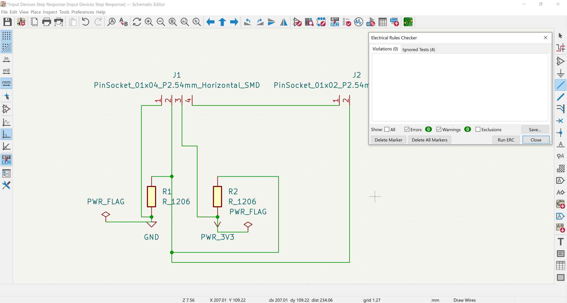
For the step response I needed: 1. Xiao ESP32-C3 represented in PinSocket 01x04 as we need GND, 3V3, and 2 pins. 2. 2 Resistors smd 1206 5M ohm. 3. 2 pieces of copper sheet will be connected to the PinSocket 01x02.
Step 3: PCB Design:
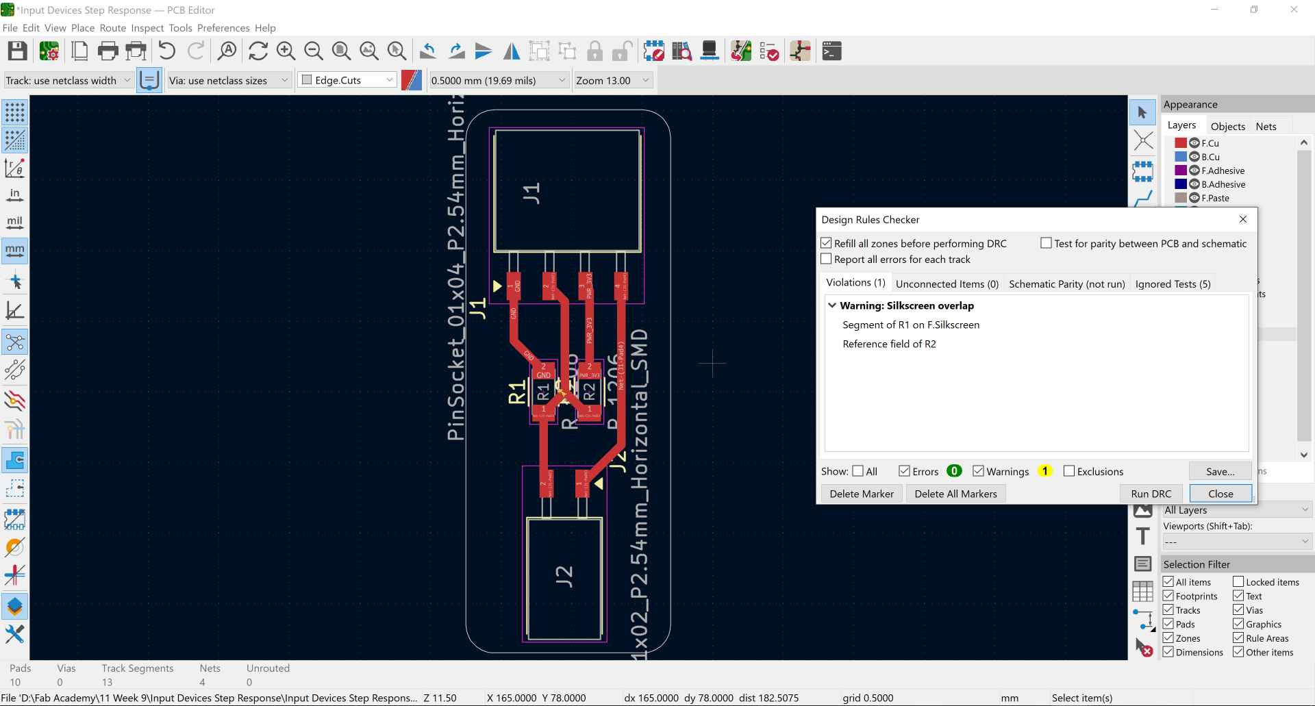
After running ERC I went to the PCB design and started routing to connect my components and made the outline of my PCB then ran a DRC. It only gave a warning about the silkscreen but we'll not be using it so I ignored it.
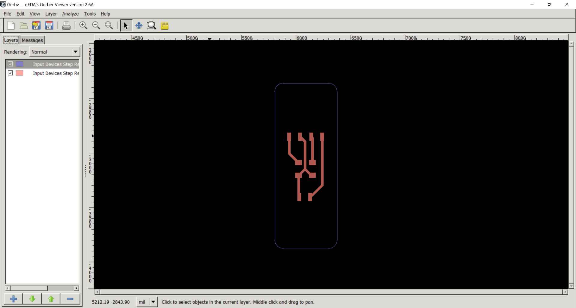
After plotting the edge cuts and F.Cu layers as gerber files I opened them using gerbv.
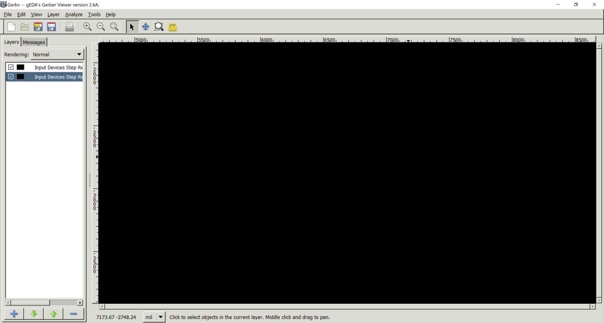
I changed their colors to black and increased the opacity then saved traces with outline and outline alone as pdfs.
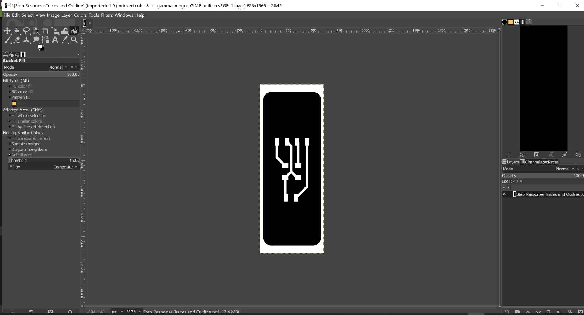
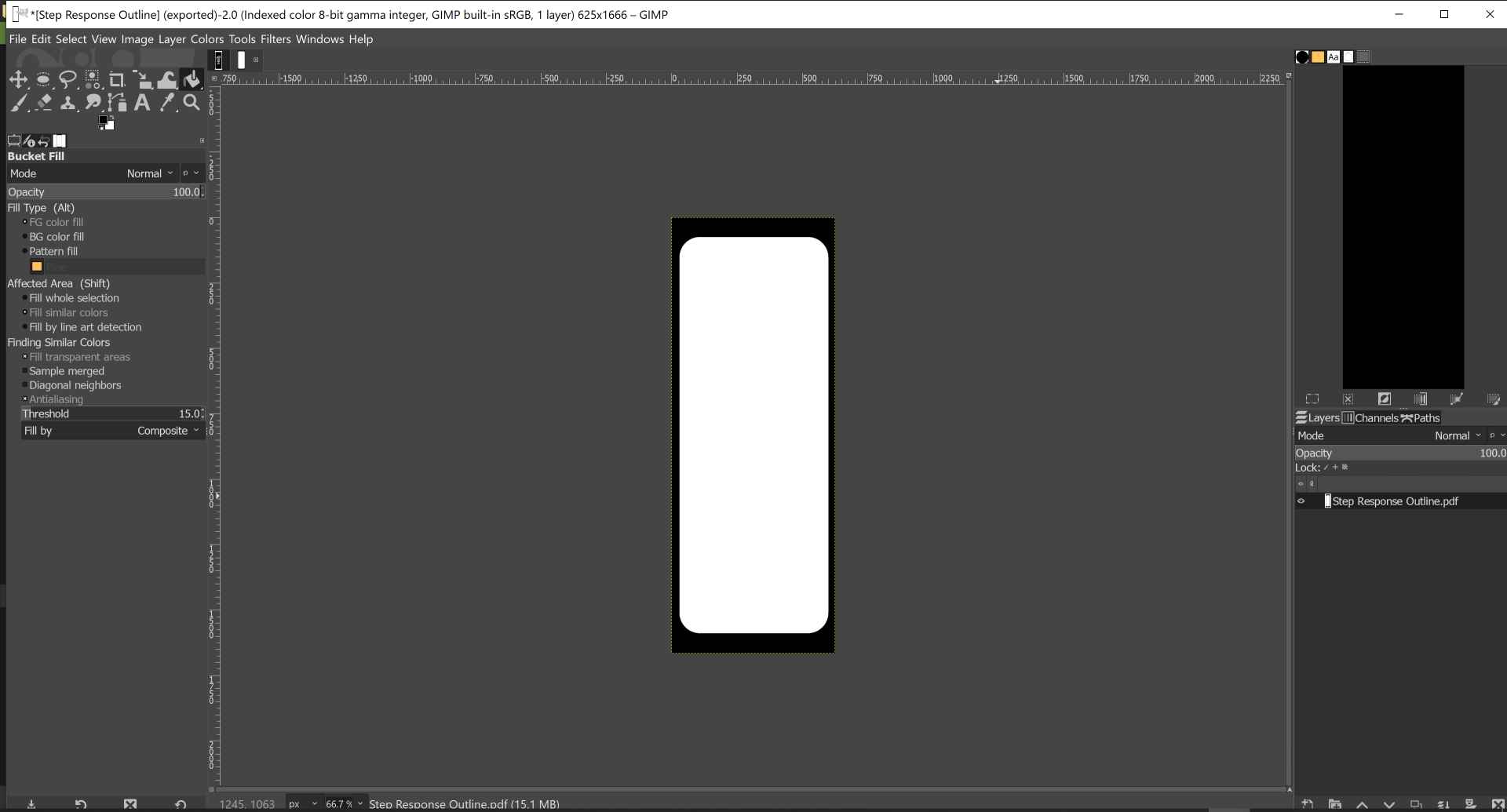
I opened the pdfs on GIMP and set the resolution to 1000 pixels/in when opening. Then by going to image menu then Mode and choose Indexed we make it black and white. After that we use the paint bucket to fill the areas we want to cut with black color. In the traces layer we go to colors menu and choose value invert. Then we export them as png.
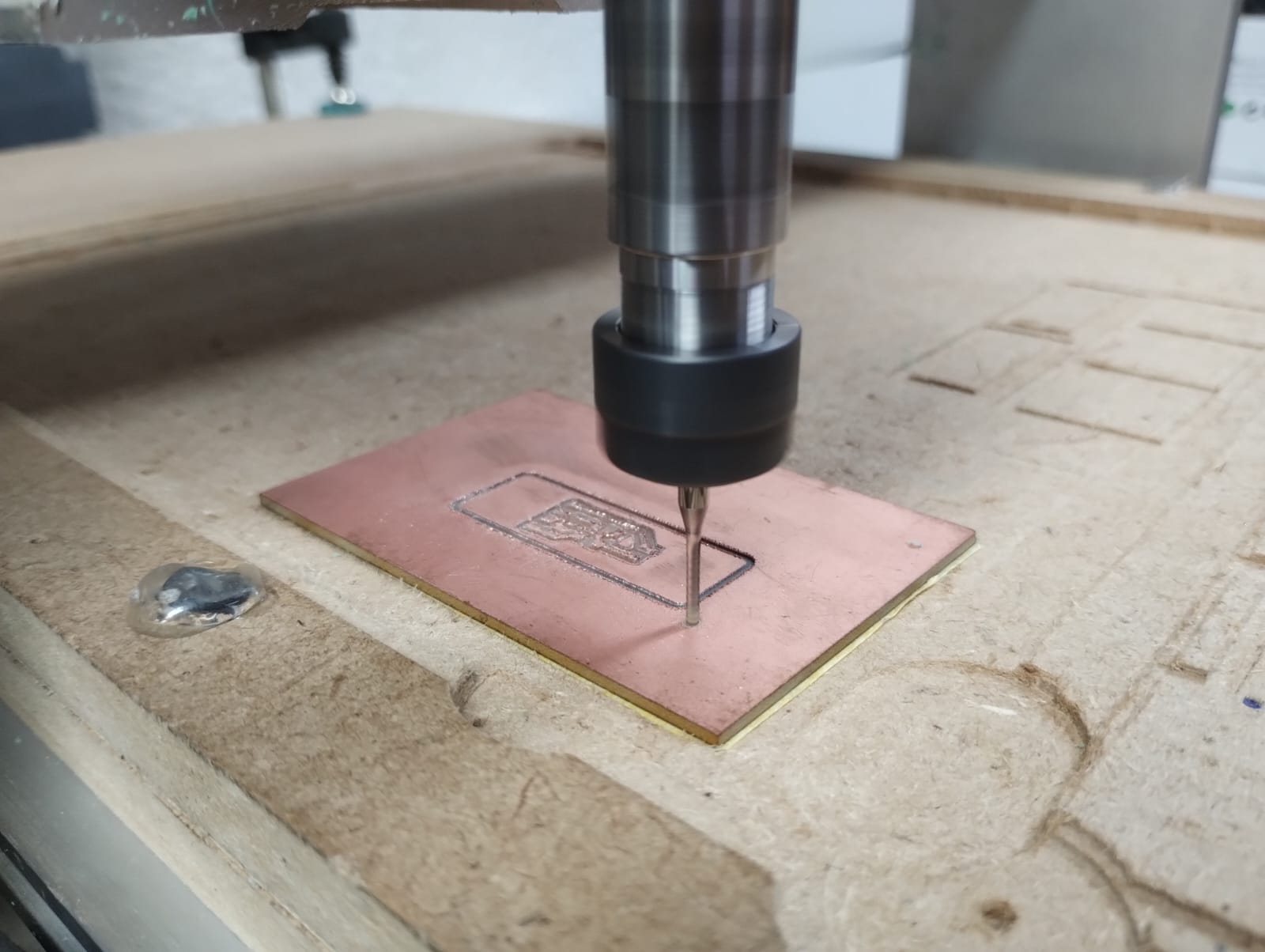
Step 4: Fabrication:
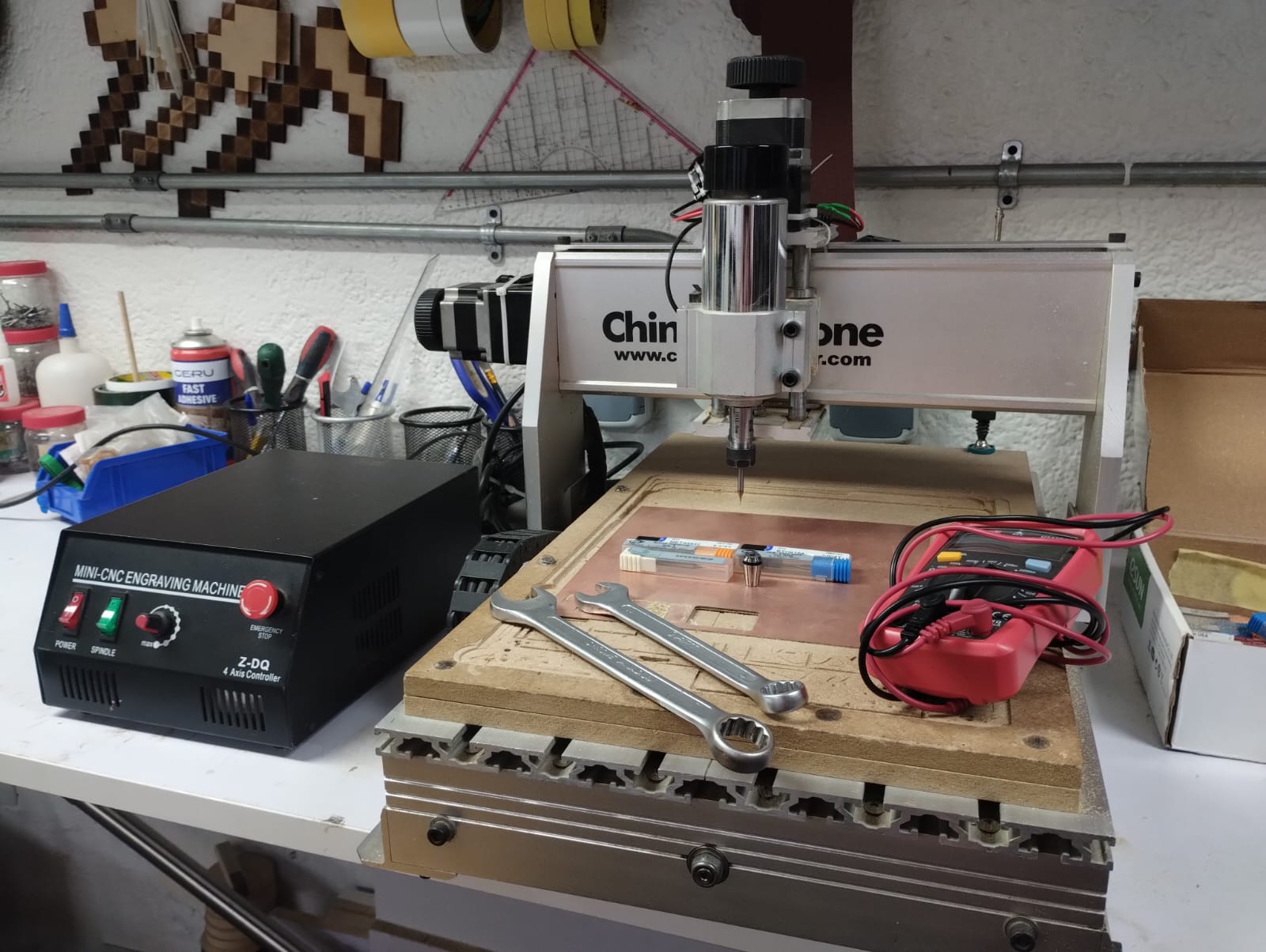
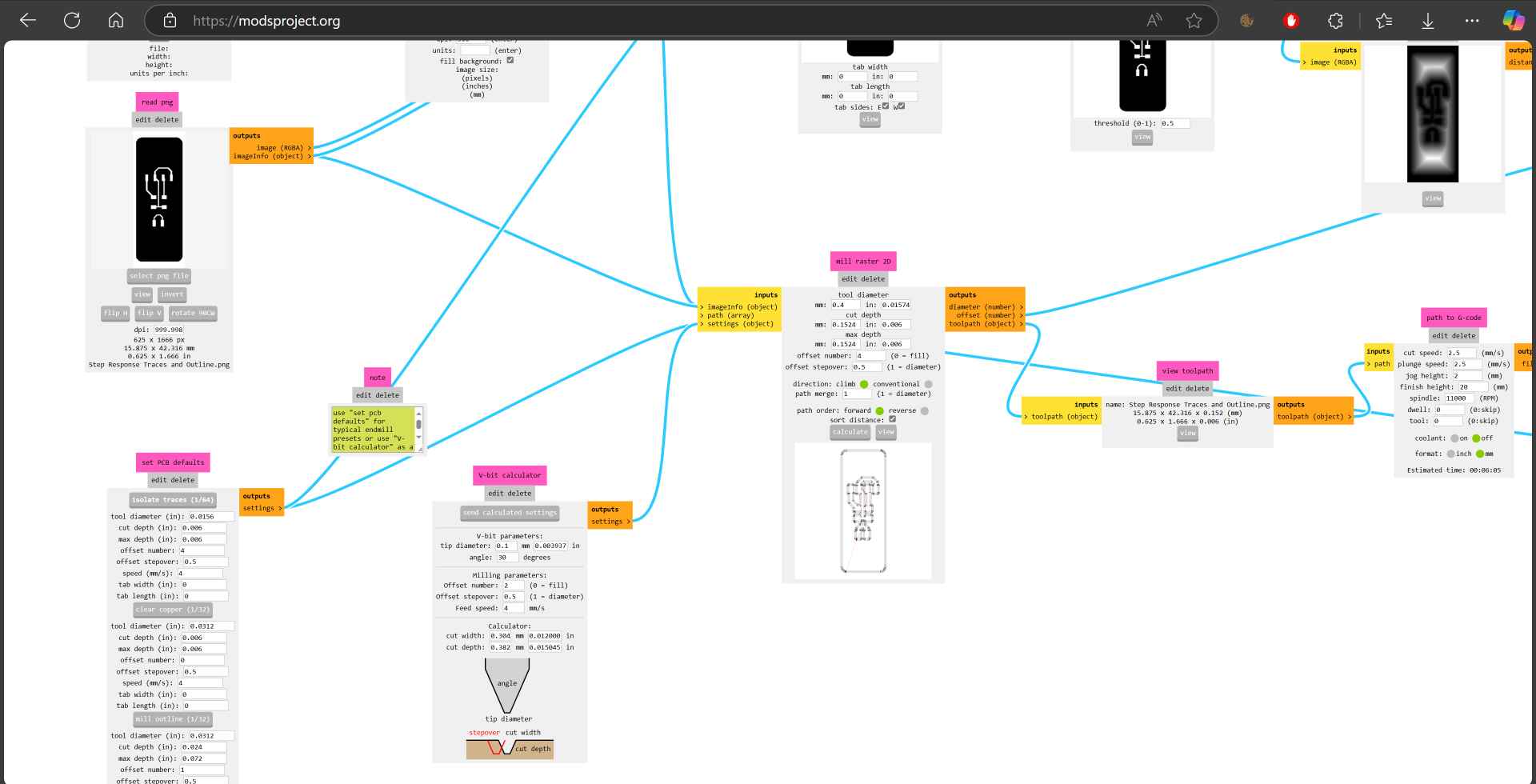
To prepare for fabrication I went to mods. First we select the traces png file and in set PCB defaults we choose isolate traces 1/64. Then in mill raster 2D we define the tool diameter which is in our case 0.4mm then calculate and the nc file will be downloaded automatically. Then we import the outline png and choose mill outline 1/32 and in the mill raster 2D I made the tool diameter 1.5mm then clicked calculate.
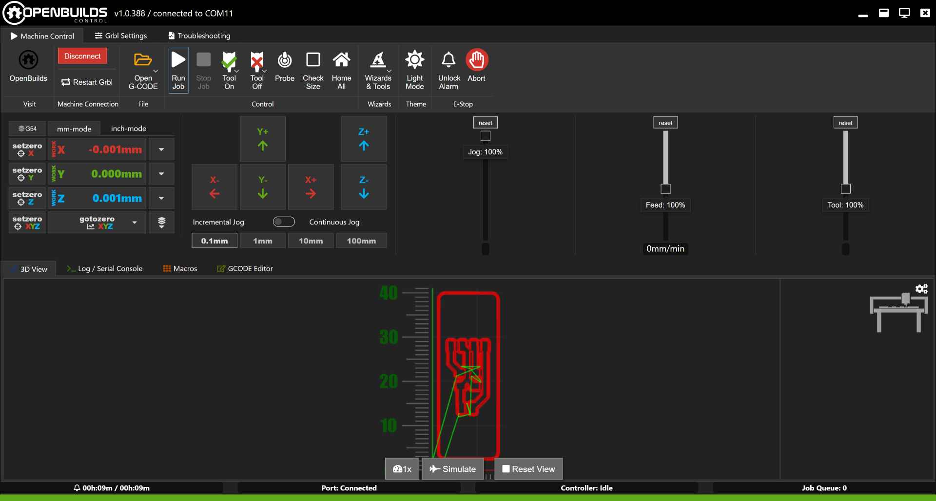
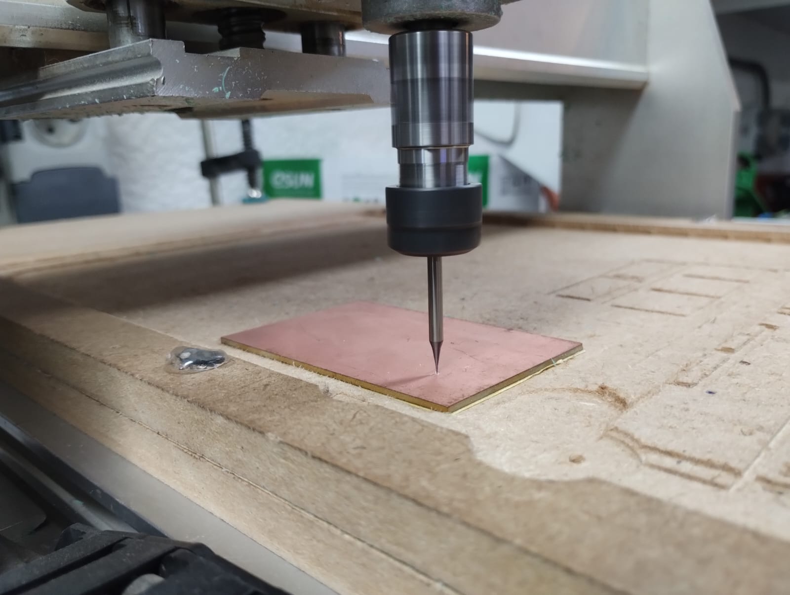
After that I went to openbuilds and uploaded the nc files and set the origin and zeroed the machine.
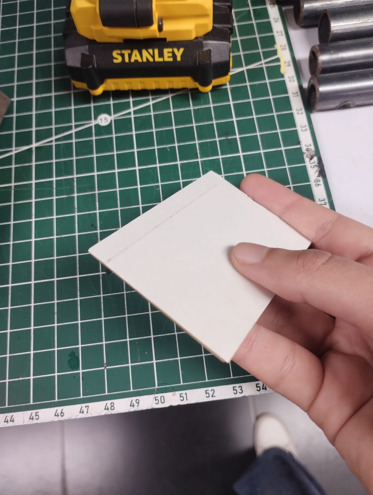
Meanwhile I was preparing the PCB sheet by adding masking tape then double face tape on it and putting it on the working area in the machine.
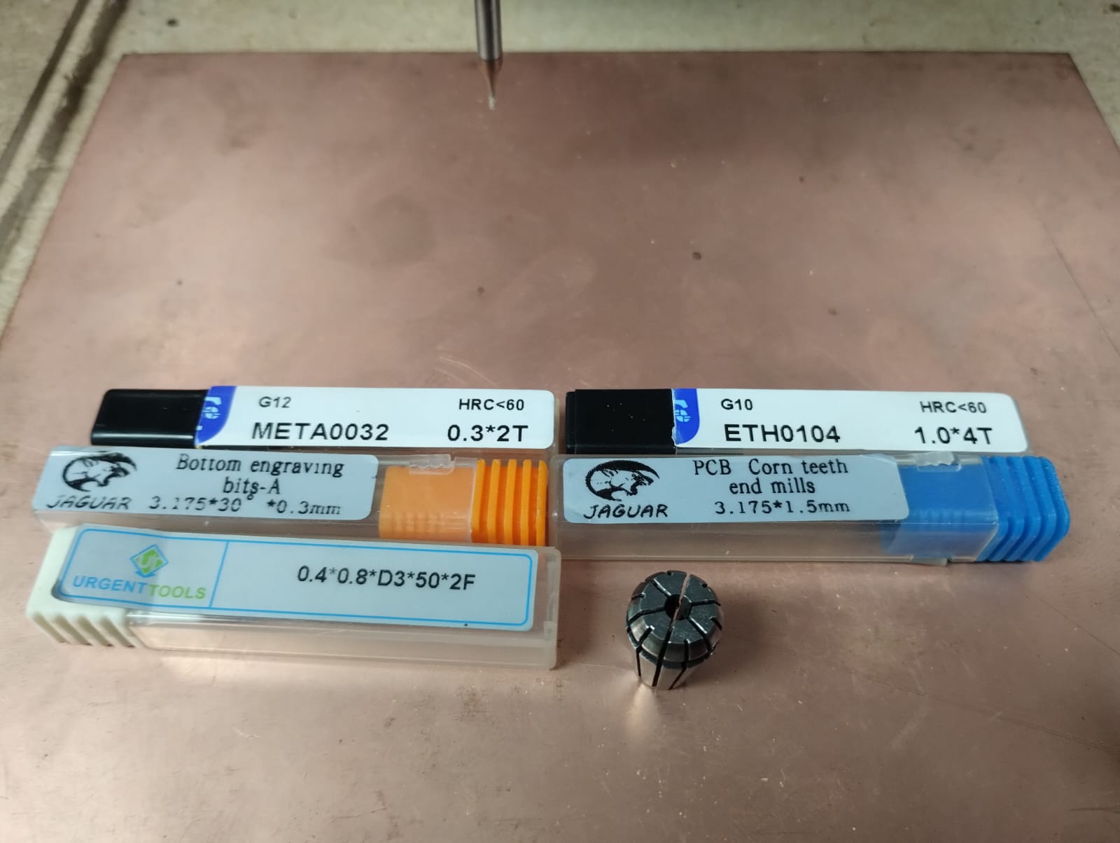
To fabricate this PCB I used the 0.4 endmill for traces and 1.5 endmill for outline.
We start with the traces..
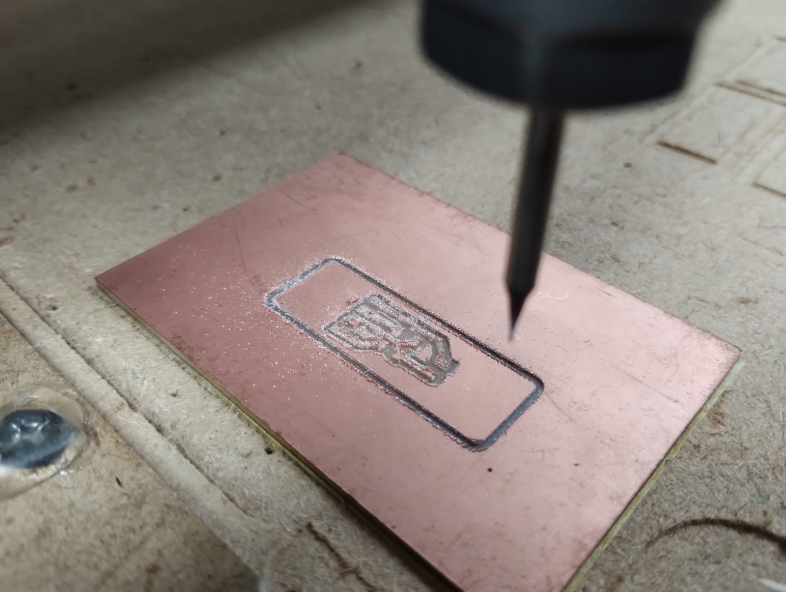
Not the best looking traces :(
Moving to the outline..
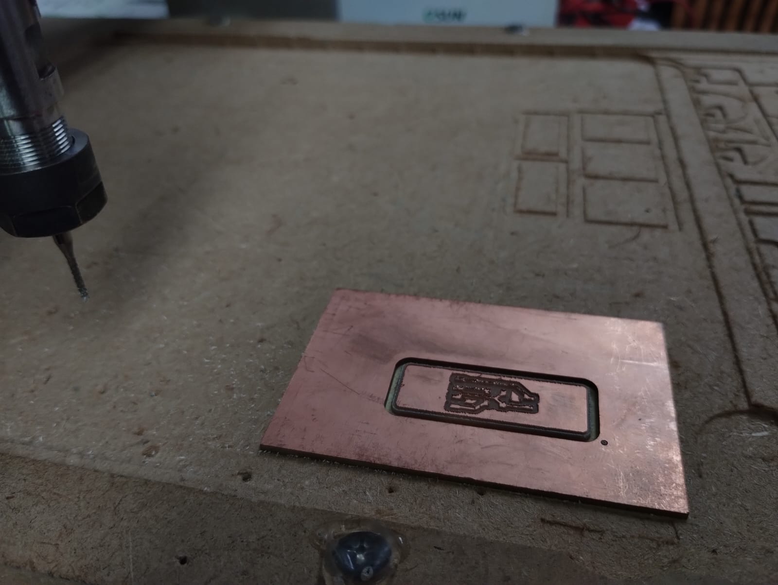
Ta Daaa!
I wasn't satisfied with how the traces looked like and was worried that it won't work but luckily after the continuity test it turned out that everything was working fine. So it's an important step.
Step 5: Soldering and Stuffing:
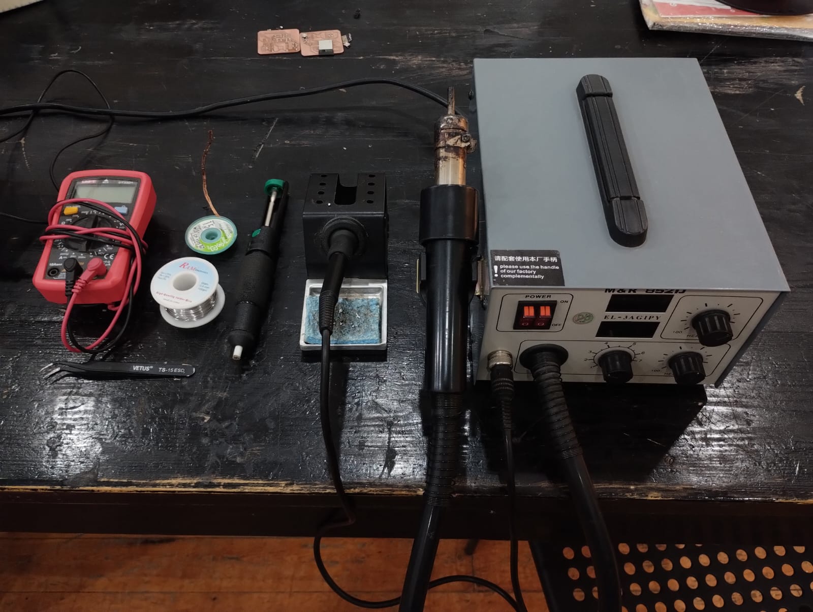
These are the heroes of soldering step but there's one missing which is the soldering paste, my hero for small soldering areas. I usually use the soldering paste and apply it with toothpick or anything with fine tip to small areas like soldering the 1206 smd resistors. In other components with many legs I start by applying solder to one of the pads then I put the component and heat it up to make the component stick to the pad then I apply solder to the other legs. I used Lead free Solders and a soldering iron with a fine tip. If there are much solder I use the solder wick to remove the excess solder.
Step 6: Wiring and Programming:
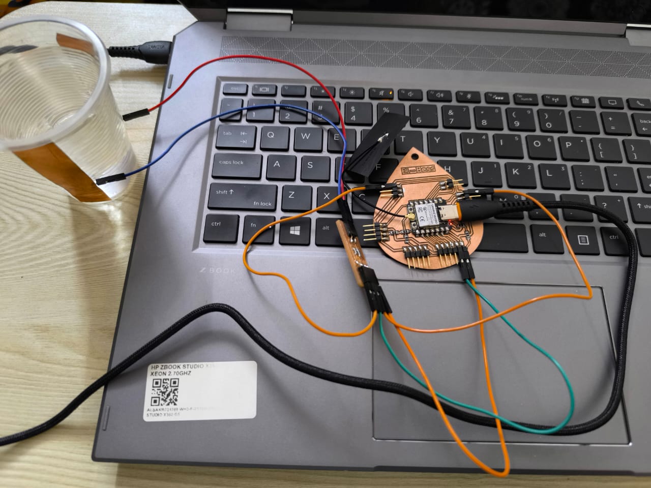
To make the wiring I used this week's PCB with the upgraded PCB of Planty I mentioned in Week 8.
At first I programmed it using the code in the link I provided earlier but there were a lot of noise and the reading weren't good at all. I searched a lot but finally I asked chatgpt about the problem and had a conversation then it provided me with the code I'm using in this video and it worked very well.
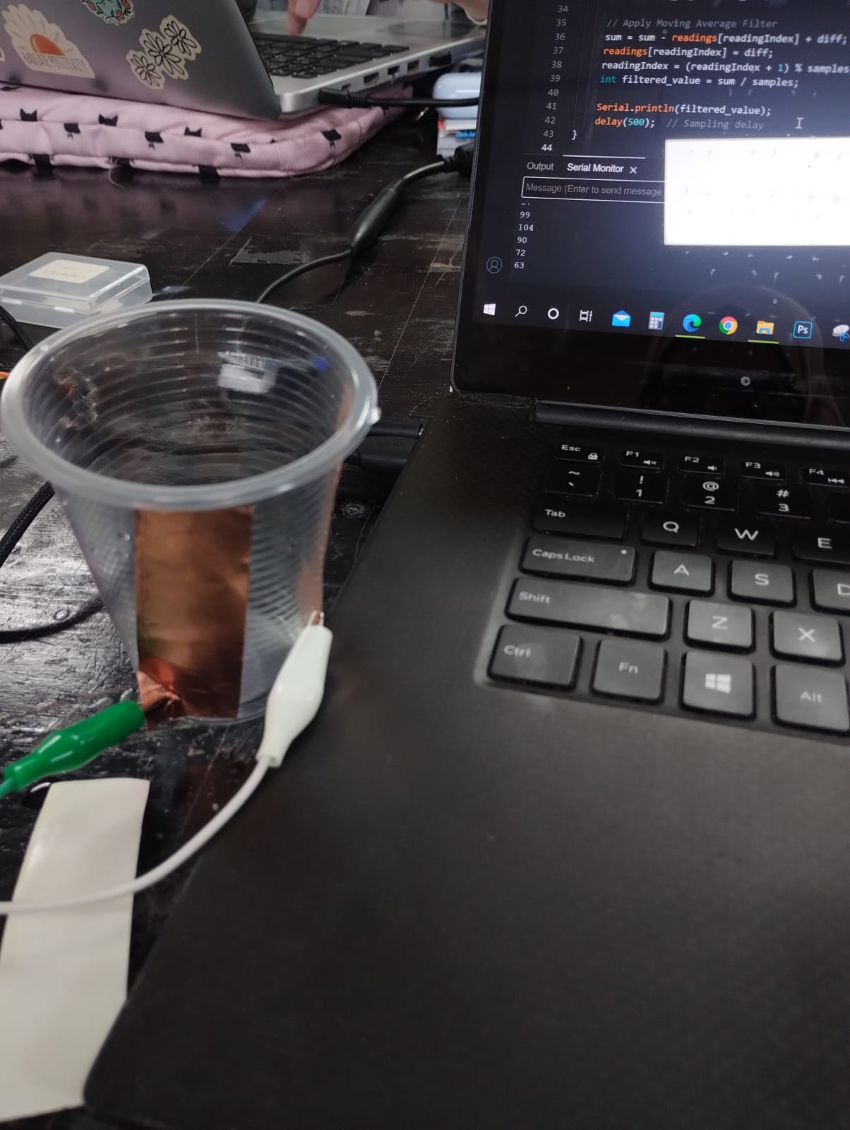
Almost no water: around 70
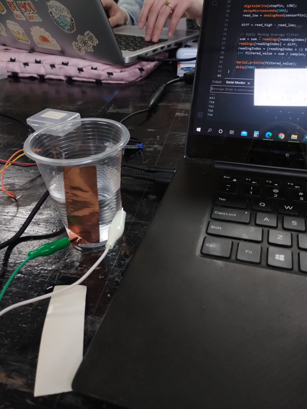
Half Cup: around 790
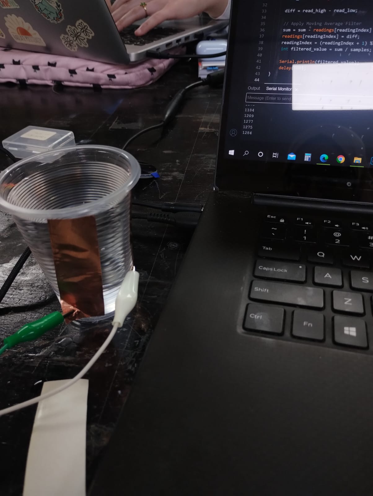
Full Cup: around 1270

int read_high;
int read_low;
int diff;
const int sensorPin = A0;
const int stepPin = D1;
// Moving Average Filter to Smooth Readings
const int samples = 10;
int readings[samples];
int readingIndex = 0;  // Renamed from 'index' to avoid conflicts
long sum = 0;

void setup() {
    pinMode(sensorPin, INPUT);
    pinMode(stepPin, OUTPUT);
    Serial.begin(115200);
    // Initialize readings array
    for (int i = 0; i < samples; i++) {
        readings[i] = 0;
    }
}

void loop() {
    digitalWrite(stepPin, HIGH);
    delayMicroseconds(300);  // Longer delay for stable response
    read_high = analogRead(sensorPin);
    digitalWrite(stepPin, LOW);
    delayMicroseconds(300);
    read_low = analogRead(sensorPin);
    diff = read_high - read_low;
    // Apply Moving Average Filter
    sum = sum - readings[readingIndex] + diff;
    readings[readingIndex] = diff;
    readingIndex = (readingIndex + 1) % samples;  // Correctly update index
    int filtered_value = sum / samples;
    Serial.println(filtered_value);
    delay(500);  // Sampling delay
}
This is the code that ChatGPT provided. It basically did some math and reduced the noise more by taking an average of the readings that we receive.
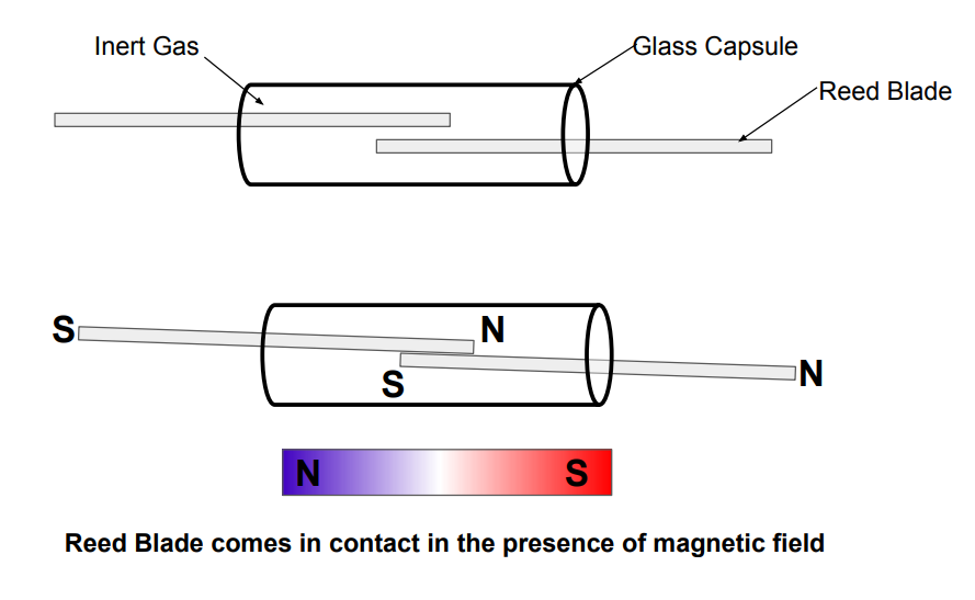
2. Magnetic Control Switch:
To start understanding the magnetic control switch I searched for it and discovered this Document that is talking about this sensor and its wiring and code. This switch detects the magnetic field, so if you bring a magnet close to it, the reed blades connect. It's very small that you don't see it with your bare eyes. But you can see the led turning on. 😉
The wiring is very simple as you need 5v or 3.3v to the VCC, GND to GND, and the signal on a pin, here I'm using it on pin D1. I used the board I designed earlier in Week 6 and fabricated in Week 8.
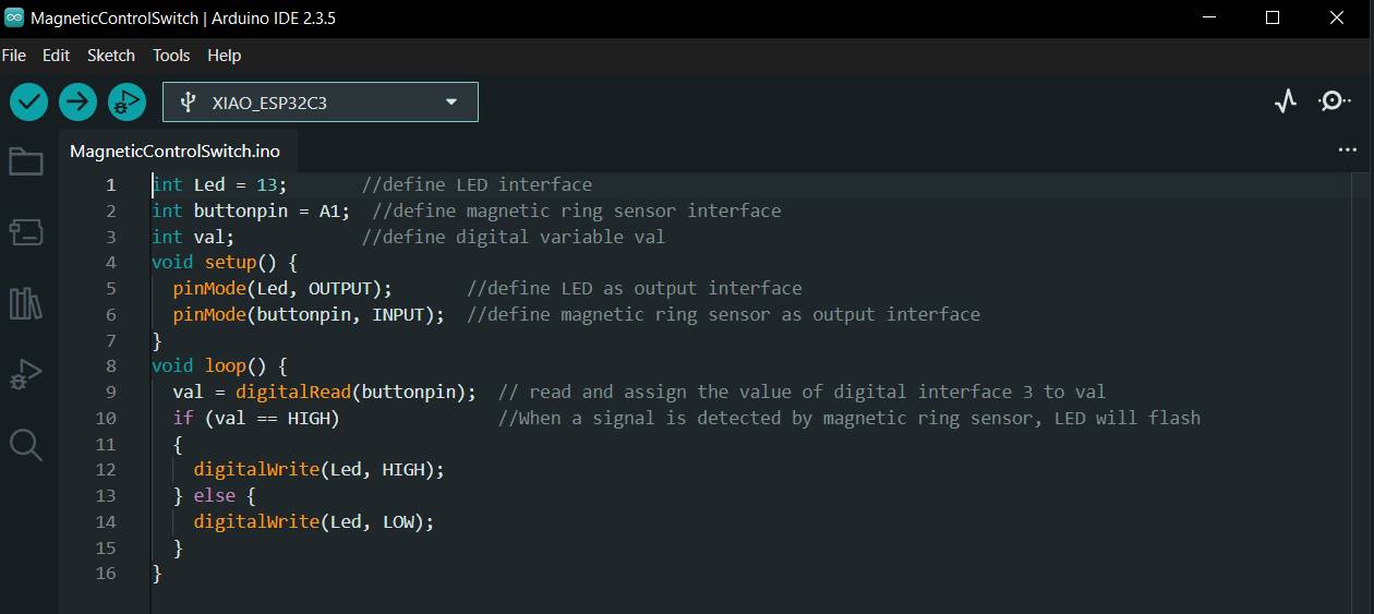
int Led = 13;       //define LED interface
int buttonpin = A1;  //define magnetic ring sensor interface
int val;            //define digital variable val
void setup() {
  pinMode(Led, OUTPUT);       //define LED as output interface
  pinMode(buttonpin, INPUT);  //define magnetic ring sensor as output interface
}
void loop() {
  val = digitalRead(buttonpin);  // read and assign the value of digital interface 3 to val
  if (val == HIGH)               //When a signal is detected by magnetic ring sensor, LED will flash
  {
    digitalWrite(Led, HIGH);
  } else {
    digitalWrite(Led, LOW);
  }
}
I used the code provided in the document and just changed the pin for the signal.