
9. Output devices
Overview
This week was working with output devices for our boards that we made in week 8.
The idea is to test them and get them working. We were given a choice of different
options to use, from LCD displays, OLED displays, motors, speakers, etc. The component
or actuator I chose is a servo motor, specifically a micro servo.
Through hands-on experimentation with three devices - a metal gear motor, a DC motor
and a servo motor - I learned not only how to calculate power by directly measuring current
and voltage, but also the complexities associated with inductive loads such as motors, where
Ohm's Law does not apply directly. This exercise reinforced the importance of using appropriate tools,
such as power supplies and multimeters, to obtain accurate measurements and understand the dynamic behavior of devices under different load conditions.
You can check out the group assignment at the following link.
Micro servo SG90
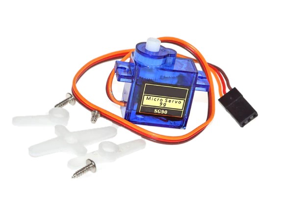
The SG90 micro servo is a small, lightweight actuator popular in robotics due to its low cost and ease of use. Capable of rotating up to 180 degrees, it allows precise control over motion, making it ideal for applications such as robotic arms, steerable vehicles, and model airplane control systems. This servo typically operates between 4.8 and 6.0 volts, and its compact size, coupled with its wide range of motion, offers a versatile and efficient solution for mechanically controlling a wide range of components in electronic projects.
Its operation is based on the ability to rotate its shaft to specific positions, which are determined by angles. Upon receiving an electrical signal, the servo's internal circuitry interprets this information and adjusts the motor position to that corresponding to the desired angle. This position control is accomplished by pulse width modulation (PWM) pulses, where the duration of the pulse sent to the servo determines the angle at which it should rotate. For example, a pulse of a certain duration might cause the servo to turn 90 degrees, while another pulse of a different duration might take it to 0 or 180 degrees.
Features
Torque
1.6kg - cm (4.8V)
Operating temperature
-30 to +60 degrees Celsius
Dead zone settings
5 microseconds
Operating voltage
3.5V ~ 6V
Size
23x12.2x12.2x29mm
Weight
13g
Function
For Boat / Car / Aircraft / Helicopter / Robot
Servo
Analog servo
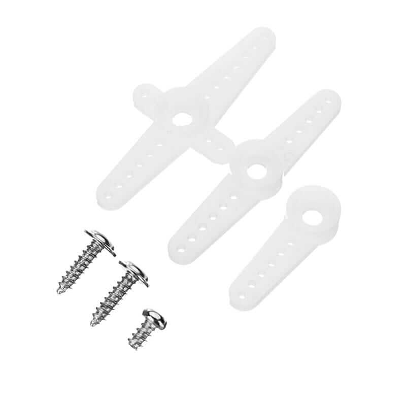
The micro servo also includes some arms to test its operation as you can see in the picture.
Testing servo on Arduino UNO
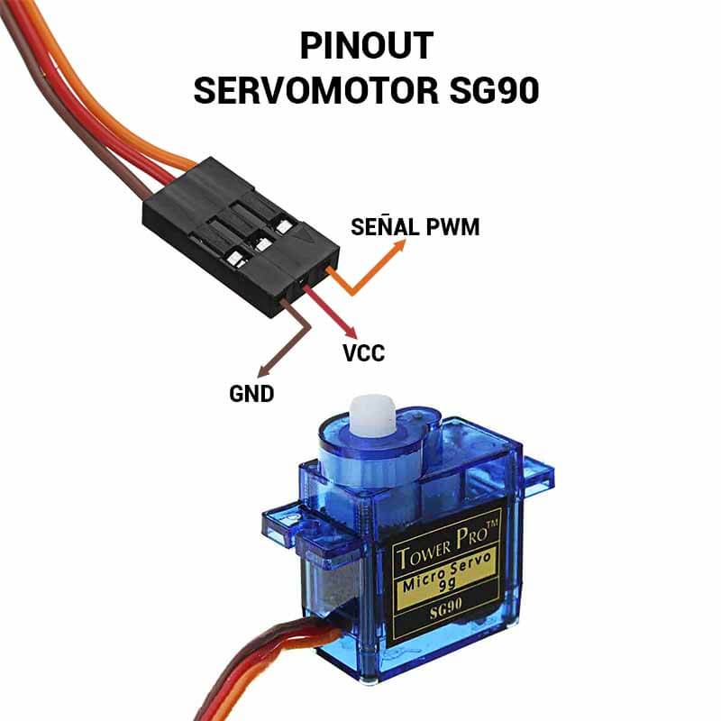
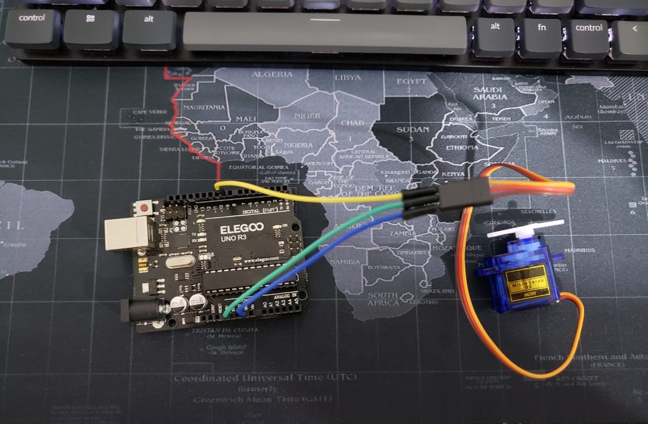
The micro servo I used has 3 pinouts. One is for GND, one for VCC and the last one for the PWM signal. These pinouts are already connected to the servo.
Before testing the servo motor on my week 8 board, I tested it on an arduino I have at home. I did this in order to prevent my board from breaking down. This way I test the servo motor operation without affecting my board.
The arduino I used is an Arduino UNO, I have this one for testing.
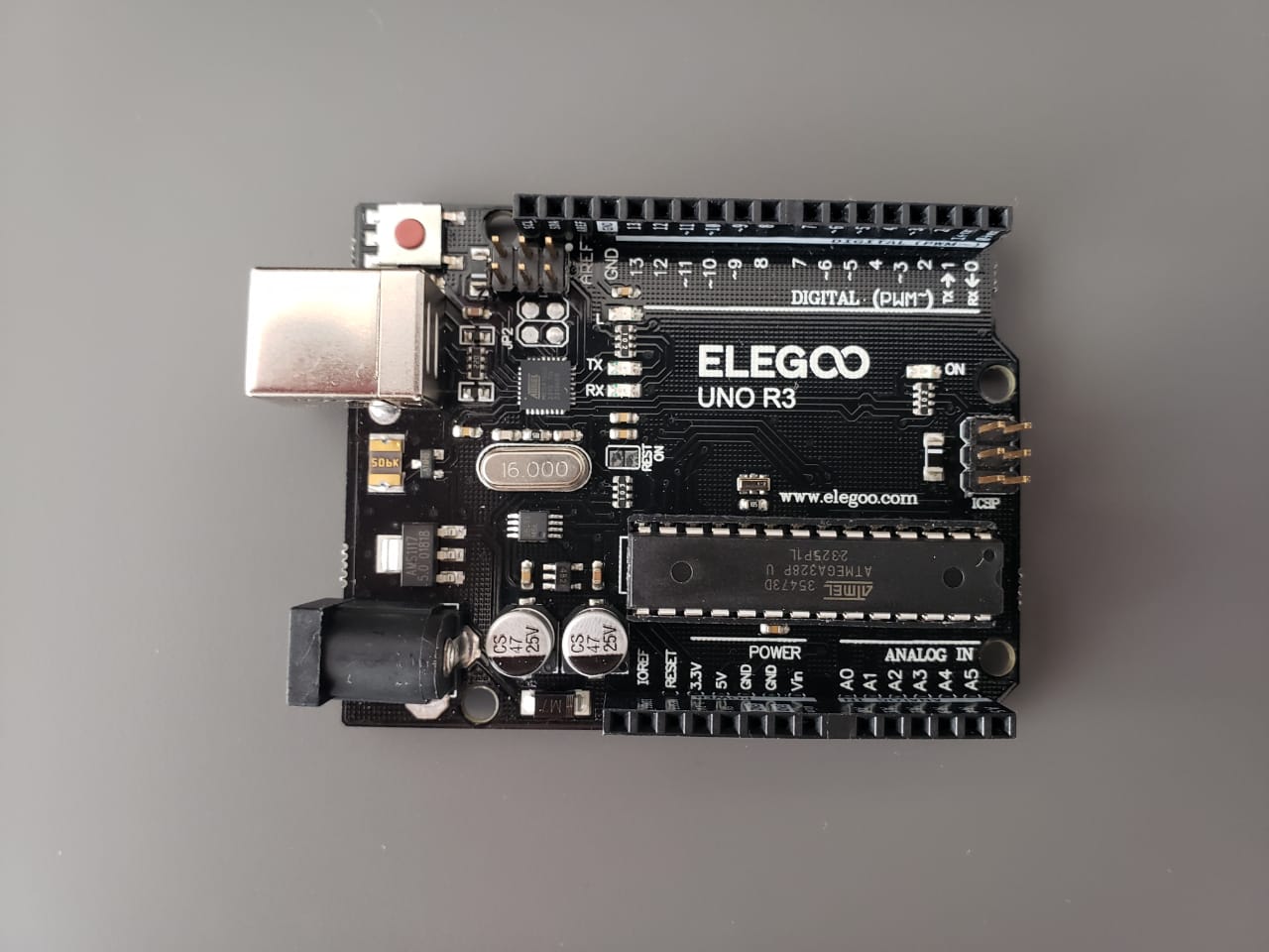
To know the connections the Arduino has well defined labels on the board to know which pins to use. The following image is the pinout of the Arduino UNO.
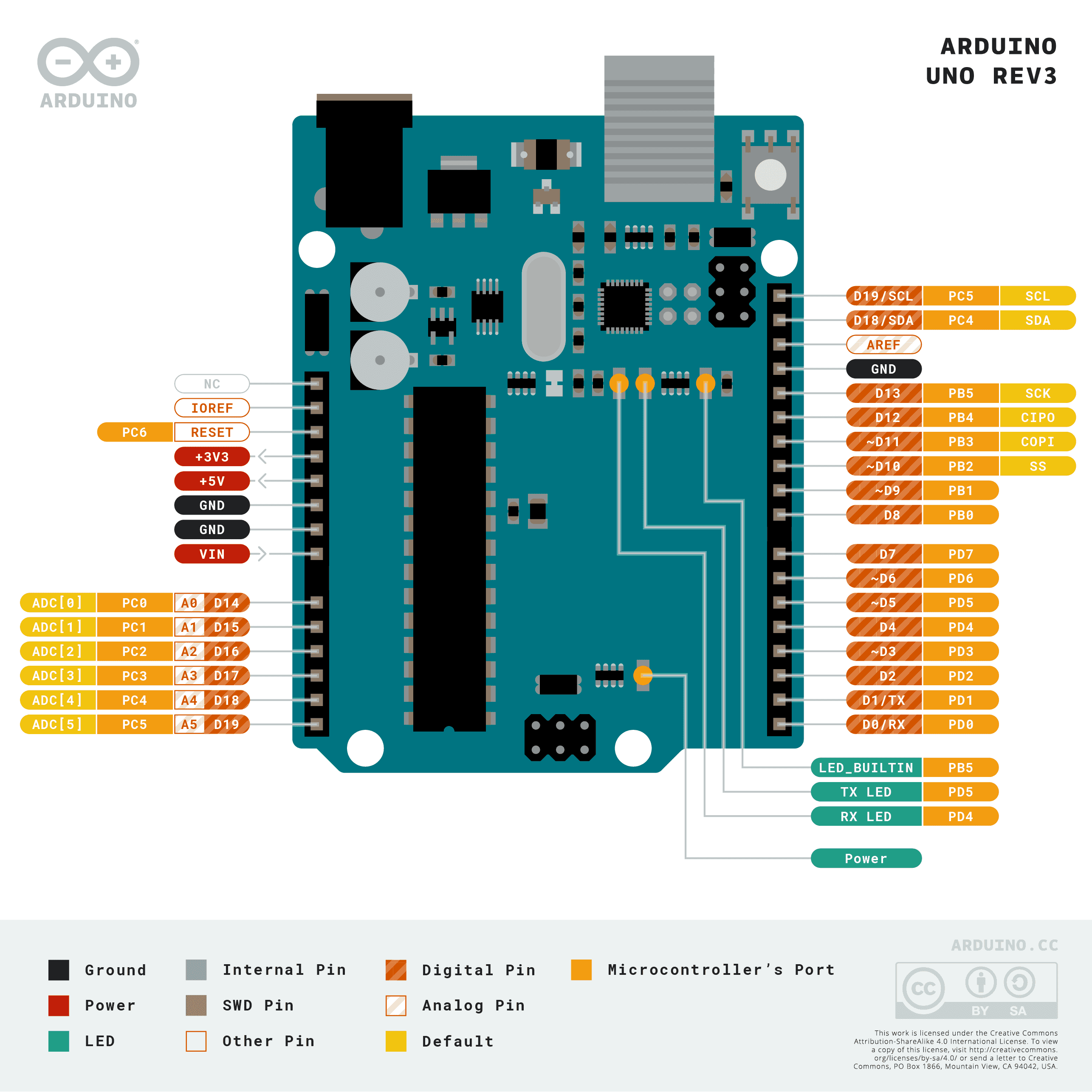
This was the connection I made, it was actually quite easy. To test it, I made a code that basically what it does is to move the servo from 0 to 180 degrees and from 180 to 0.
Here my code:
    // Include the Servo library to control the servo motor.
    #include <Servo.h>

    // Create a servo object named myServo for controlling a servo.
    Servo myServo;

    // Attach the servo on pin 9 to the servo object for PWM control.
    void setup() {
        myServo.attach(9);
    }

    // Move the servo from 0 to 180 degrees
    void loop() {
        // Goes from 0 degrees to 180 degrees
        for(int angle = 0; angle <= 180; angle += 1) {
        myServo.write(angle);              // Tell the servo to go to the position in angle.
        delay(15);                         // Wait 15ms between each position to slow down the movement.
        }

        // Move the servo from 180 to 0 degrees
        for(int angle = 180; angle >= 0; angle -= 1) { // Goes from 180 degrees back to 0 degrees
        myServo.write(angle);              // Tell the servo to go to the position in angle.
        delay(15);                         // Wait 15ms between each position to slow down the movement.
        }
    }
Result
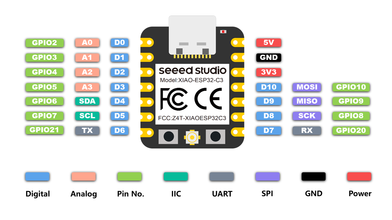
SG90 and Xiao ESP32 Servo Pinout
The microcontroller I used in week 8 is a Xiao Esp32C3. For the PWM signal I can use any pinout from D0 to D10. And for the voltage I used 5V.
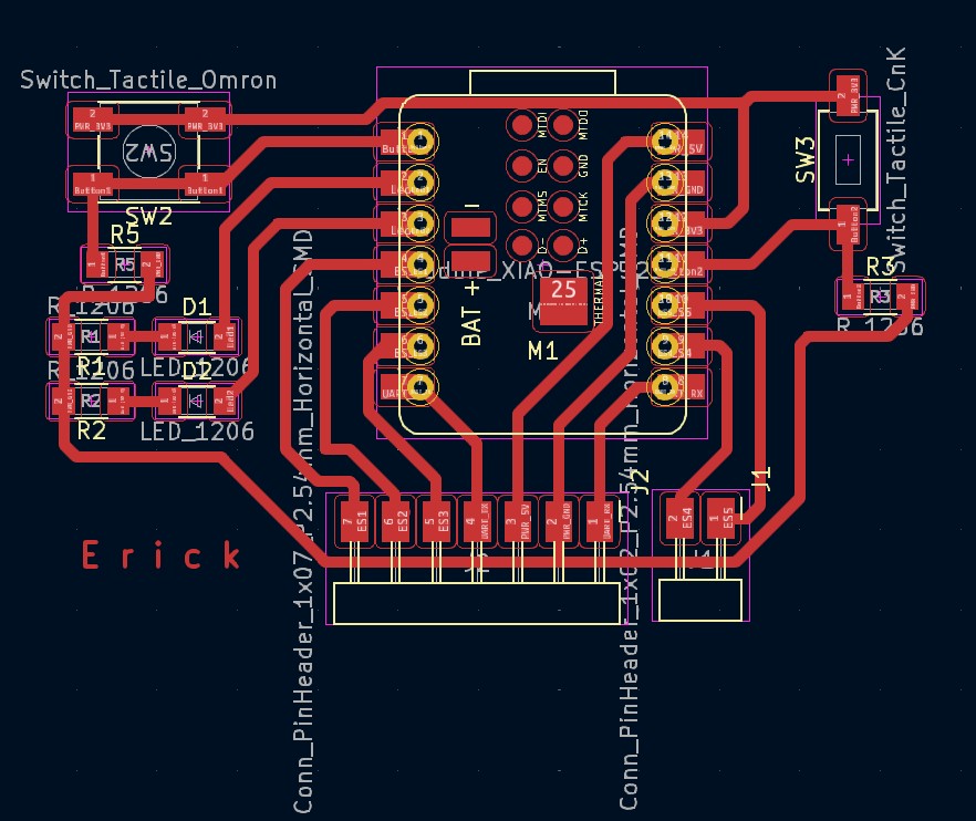
To find out the connections on the board, check the design I made in KiCad. I used pin 2 for GND, pin 3 for VCC and pin 7 as my PWM signal pin. You can see these pinouts below the Xiao Esp32. That was the configuration I did in week 8. But it is important to know it to make the correct connections. You can check the week 8 page at the following link.
Test Run: Code Implementation and Testing
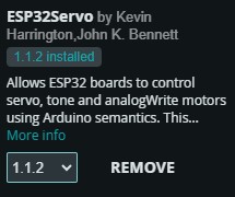
To test the servo operation, I made a code in Arduino IDE. To test it I had to install a library in the library manager. The library is called ESP32 Servo. This library is made for the microcontroller I used, since the Servo library does not work for the Xiao Esp32.
The code I made positions the servo at 90 degrees as the starting angle. Instead of using a potentiometer I used the two buttons I had designed in week 8. When I press one button the servo turns at 0 degrees and when I press the other button the servo turns in the other direction at 180 degrees.
    // Include the ESP32Servo library
    #include <ESP32Servo.h>

    // Define pin connections
    const int servoPin = D3;   // Pin connected to the servo
    const int buttonPin1 = D0; // Pin connected to the first button
    const int buttonPin2 = D10; // Pin connected to the second button

    // Create a Servo object
    Servo myServo;

    // Initial servo angle and increment for button press
    int angle = 90; // Initial angle of the servo
    int increment = 3; // Amount to increase/decrease the angle when a button is pressed

    // Variables for debouncing
    unsigned long lastPressTime = 0; // Time when a button was last pressed
    const unsigned long debounceDelay = 50; // Debounce delay to prevent multiple detections

    // Setup configuration
    void setup() {
        pinMode(buttonPin1, INPUT_PULLUP); // Initialize the first button pin as an input with internal pull-up resistor
        pinMode(buttonPin2, INPUT_PULLUP); // Initialize the second button pin as an input with internal pull-up resistor
        myServo.attach(servoPin); // Attach the servo on the servoPin to the Servo object
        myServo.write(angle); // Initialize the servo to its initial position
    }

    // Main program loop
    void loop() {
        // Check for button press with debouncing
        if (millis() - lastPressTime > debounceDelay) {
        // If the first button is pressed, move the servo in one direction
        if (digitalRead(buttonPin1) == LOW) {
            if(angle < 180) { // Check if the angle is less than 180 degrees
            angle += increment; // Increase the angle
            myServo.write(angle); // Move the servo to the new angle
            }
            lastPressTime = millis(); // Update the lastPressTime
        }

        // If the second button is pressed, move the servo in the opposite direction
        if (digitalRead(buttonPin2) == LOW) {
            if(angle > 0) { // Check if the angle is greater than 0 degrees
            angle -= increment; // Decrease the angle
            myServo.write(angle); // Move the servo to the new angle
            }
            lastPressTime = millis(); // Update the lastPressTime
        }
        }
    }
Result
Oled display
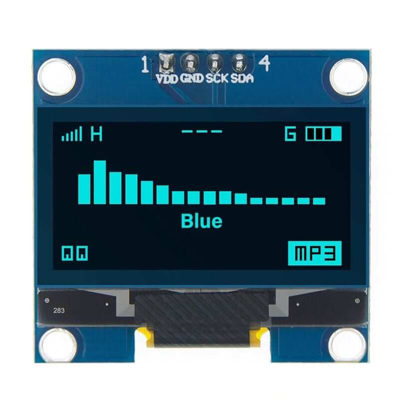
Display Oled Blue 128×64 1.3″ I2C SH1106 is SH1106 driver based display that allows displaying text and graphics with I2C communication interface , being able to work with voltage from 3V to 5V.
The 128×64 Blue Oled Display is ideal for displaying text, bitmaps, pixels, rectangles, circles and lines; or in projects for monitoring, industrial equipment, portable medical or Smartwatch.
How it works?
An OLED (organic light-emitting diode) display works by using a layer of organic material that emits light when an electric current is applied. Unlike LCD screens, OLEDs do not require a backlight, as each pixel emits its own light. This allows OLED displays to be thinner and lighter, and provide higher contrast and more vibrant colors. When voltage is applied to the electrodes of the display, electrons and holes combine in the organic material, producing photons (light). The intensity and color of the light can be controlled by varying the voltage and the composition of the organic material.
Features:
Type
OLED Display
Operating Voltage
3V – 5.5V DC
Resolution
128×64 pixels – 1.3 "
Monochrome
White Pixels
Driver
SH1106
Interface
I2C (I2C address: 0x3C)
Pins
4 (VDD, GND, SCK, and SDA)
Dimensions
35mm x 33mm x 4mm
Viewing Angle
>160º
Ultra Low Power Consumption
0.04W when all pixels are on
Operating Temperature
-30ºC ~ 70ºC
Weight
5g
In general, these are the main characteristics of the oled display, but you can consult more information about this component in its datasheet in the following link.
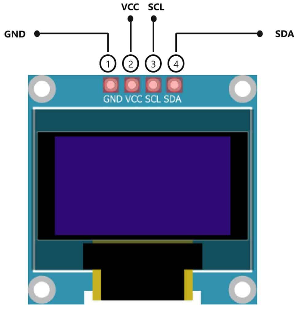
Finally, this image shows the oled display pinout information. The connection is simple, because it has few pins.
Hello world example
	#include <Wire.h>
	#include <Adafruit_GFX.h>
	#include <Adafruit_SSD1306.h>

	#define SCREEN_WIDTH 128 // OLED display width, in pixels
	#define SCREEN_HEIGHT 64 // OLED display height, in pixels

	// Declaration for an SSD1306 display connected to I2C (SDA, SCL pins)
	#define OLED_RESET -1 // Reset pin # (or -1 if sharing Arduino reset pin)
	#define SCREEN_ADDRESS 0x3C // I2C address for the OLED display

	Adafruit_SSD1306 display(SCREEN_WIDTH, SCREEN_HEIGHT, &Wire, OLED_RESET);

	void setup() {
		// Initialize the display
		if (!display.begin(SSD1306_SWITCHCAPVCC, SCREEN_ADDRESS)) {
		Serial.println(F("SSD1306 allocation failed"));
		for (;;);
		}

		// Clear the display buffer
		display.clearDisplay();

		// Set text size and color
		display.setTextSize(2); // Increase text size
		display.setTextColor(SSD1306_WHITE);

		// Set cursor position
		display.setCursor(10, 25);

		// Display "Hello, World!"
		display.println("Hello, World!");

		// Show the buffer on the display
		display.display();
	}

	void loop() {
		// Nothing to do here
	}
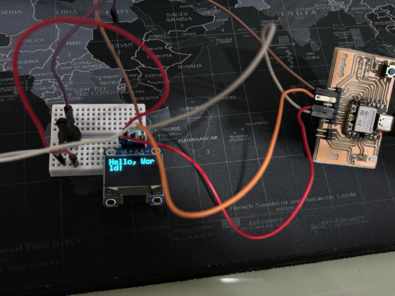
This code initializes an OLED display and shows the message "Hello, World!" with an increased text size. First, the necessary libraries for handling the OLED display are included, and the screen dimensions and I2C address are defined. In the setup function, the display is initialized and the buffer is cleared. Then, the text size and color are set, as well as the cursor position. Finally, the message "Hello, World!" is displayed on the screen. The loop function is empty because the message does not need to be updated continuously.
Result
Bouncing ball game
To further test the oled display, I decided to make a game. Thinking which one I could make I chose "bouncing ball game" because I have 2 buttons on my board to move the bar. I liked the result very much.

Here my code:
	#include <Wire.h>
	#include <Adafruit_GFX.h>
	#include <Adafruit_SSD1306.h>

	#define SCREEN_WIDTH 128 // OLED display width, in pixels
	#define SCREEN_HEIGHT 64 // OLED display height, in pixels

	// Declaration for an SSD1306 display connected to I2C (SDA, SCL pins)
	#define OLED_RESET -1 // Reset pin # (or -1 if sharing Arduino reset pin)
	#define SCREEN_ADDRESS 0x3C // I2C address for the OLED display

	Adafruit_SSD1306 display(SCREEN_WIDTH, SCREEN_HEIGHT, &Wire, OLED_RESET);

	const int button1Pin = D0;
	const int button2Pin = D10;

	int barX = SCREEN_WIDTH / 2; // Initial X position of the bar
	int barY = SCREEN_HEIGHT - 10; // Y position of the bar
	int barWidth = 20; // Width of the bar
	int barHeight = 5; // Height of the bar
	int barSpeed = 4; // Speed of the bar

	int dotX, dotY; // Position of the dot
	int dotSpeedX = 2; // Speed of the dot in X direction
	int dotSpeedY = 2; // Speed of the dot in Y direction

	void setup() {
		// Initialize buttons
		pinMode(button1Pin, INPUT_PULLUP);
		pinMode(button2Pin, INPUT_PULLUP);

		// Initialize the display
		if (!display.begin(SSD1306_SWITCHCAPVCC, SCREEN_ADDRESS)) {
		Serial.println(F("SSD1306 allocation failed"));
		for (;;);
		}

		// Clear the display buffer
		display.clearDisplay();
		display.display();

		// Initialize the dot position
		dotX = random(0, SCREEN_WIDTH);
		dotY = 0;
	}

	void loop() {
		// Read the state of the buttons
		int button1State = digitalRead(button1Pin);
		int button2State = digitalRead(button2Pin);

		// Move the bar based on button presses
		if (button1State == LOW) {
		barX -= barSpeed; // Move left
		if (barX < 0) barX = 0;
		}
		if (button2State == LOW) {
		barX += barSpeed; // Move right
		if (barX > SCREEN_WIDTH - barWidth) barX = SCREEN_WIDTH - barWidth;
		}

		// Move the dot
		dotX += dotSpeedX;
		dotY += dotSpeedY;

		// Check if the dot hits the walls
		if (dotX < 0 || dotX > SCREEN_WIDTH) {
		dotSpeedX = -dotSpeedX;
		}

		// Check if the dot hits the top
		if (dotY < 0) {
		dotSpeedY = -dotSpeedY;
		}

		// Check if the dot hits the bottom (lose condition)
		if (dotY > SCREEN_HEIGHT) {
		// Reset the game
		display.clearDisplay();
		display.setTextSize(2);
		display.setTextColor(SSD1306_WHITE);
		display.setCursor(10, 20);
		display.println("You lost!");
		display.display();
		delay(2000); // Show "You lost!" for 2 seconds
		// Reinitialize positions
		dotX = random(0, SCREEN_WIDTH);
		dotY = 0;
		barX = SCREEN_WIDTH / 2;
		return;
		}

		// Check collision with the bar
		if (dotX >= barX && dotX <= (barX + barWidth) && dotY >= barY && dotY <= (barY + barHeight)) {
		dotSpeedY = -dotSpeedY;
		}

		// Clear the display
		display.clearDisplay();

		// Draw the bar
		display.fillRect(barX, barY, barWidth, barHeight, SSD1306_WHITE);

		// Draw the dot
		display.fillCircle(dotX, dotY, 3, SSD1306_WHITE);

		// Update the display
		display.display();

		// Small delay for stability
		delay(50);
	}
The code controls an OLED display and two buttons to move a bar and a dot on the screen. First, it includes the necessary libraries and defines the dimensions and I2C address of the OLED display. Then, it sets up the pins for the buttons and initializes the positions of the bar and the dot. In the main loop, the code reads the button states to move the bar left or right. The dot moves automatically and bounces when it hits the screen edges. If the dot reaches the bottom of the screen without hitting the bar, a "You lost!" message is displayed and the game resets after a short delay.