
2. Computer-Aided Design
Overview
The second week's activity is to design a figure in 2D and 3D. For the 3D design, I used Fusion 360 and SolidWorks, and for the 2D design, I used Inkscape and Figma. This activity was a challenge since I had never used modeling software before. Fusion 360 was easy to use, with an understandable interface. However, with the knowledge I gained from Fusion 360, I practiced using SolidWorks. Both software tools are complete, and I feel comfortable working with either one.
Fusion 360
What is Fusion 360?
Fusion 360 is a cloud-based 3D modeling, CAD, CAM, and CAE tool developed by Autodesk. It enables users to design, simulate, and manufacture products with an integrated and intuitive platform. Fusion 360 is widely used for creating precise mechanical components, prototypes, and complex assemblies in various industries, including engineering and product design.
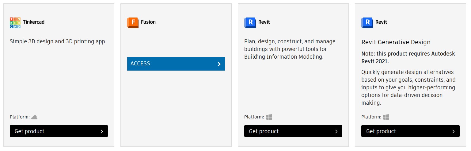
To get started, go to the AUTODESK website to install the software.
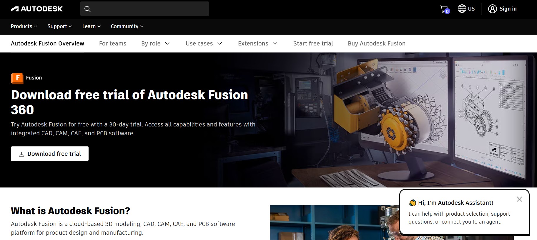
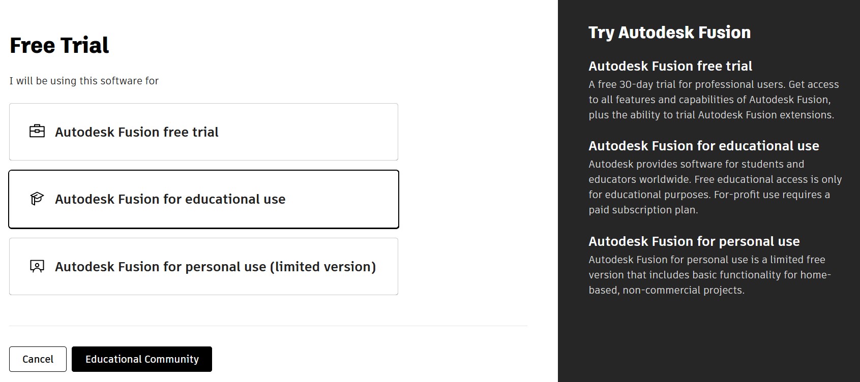
As a university student, I can use the software through my institution’s license. The next step was to click on "Download free trial" and select the second option: "Autodesk Fusion for educational use".
After selecting "Get started", I filled out a form and created an account.

We indicate "student" in the educational role and enter our date of birth.

We complete a small form with our information, name, email and password.
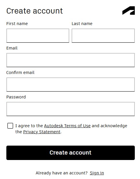
When finished, our account has been created and we log in.
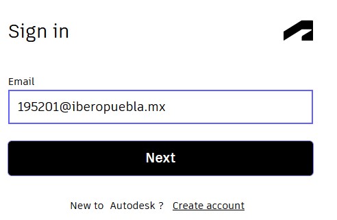
After creating the account, I was able to download Fusion 360.
3D Model in Fusion 360
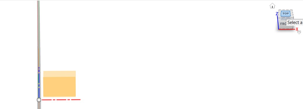
The figure I made in fusion 360 is the one shown in the following image in red. It is a filament spool. For this figure I used the parametric model.
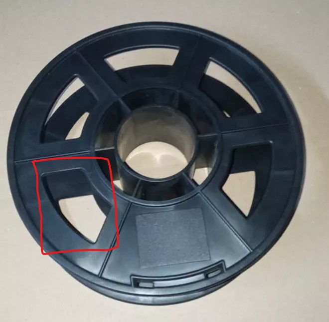
The parametric model in Fusion 360 is a design technique that allows you to establish relationships and parameters between different geometric elements, which makes it easy to modify and update the design efficiently and accurately.
Steps to create the figure in Fusion 360:
1. After installing the software (which is very easy to do), we open it.
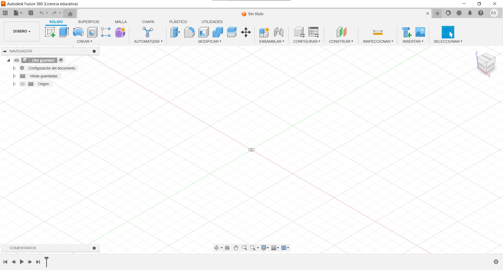
2. Select the option: Create Sketch.
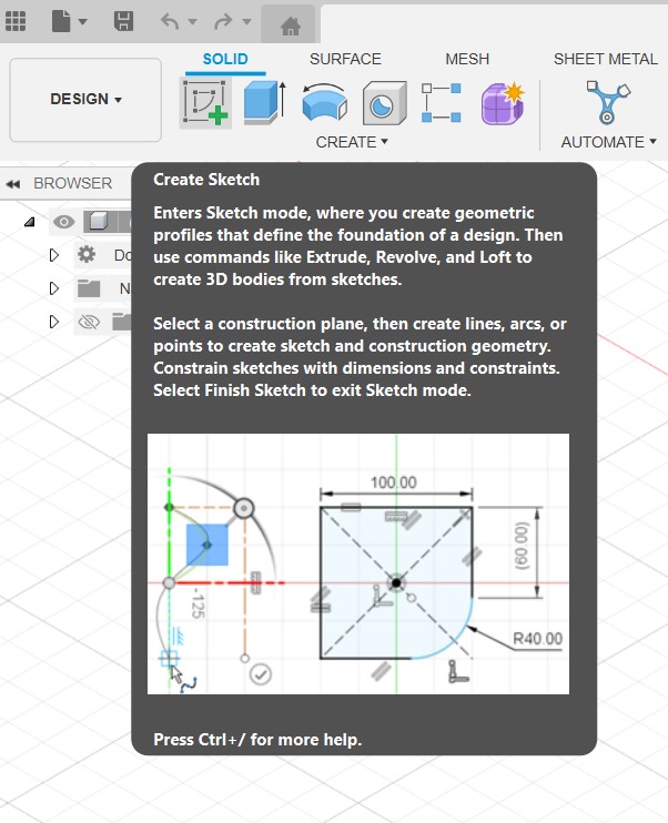
3. Next, we select one side of the sketch. I selected the top face.
4. To start with the figure, we select the circle and draw it in the center, regardless of the size.
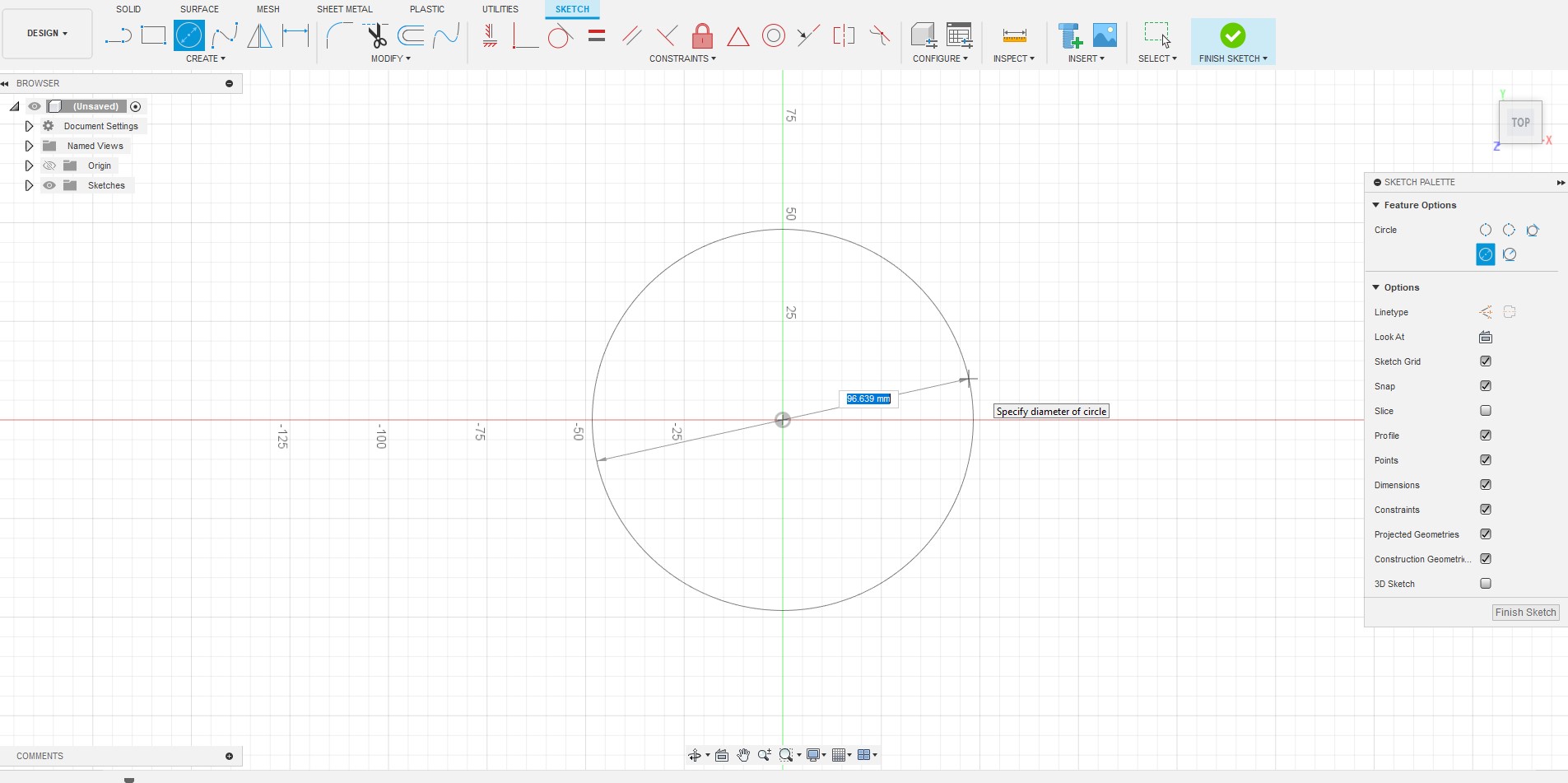
5. Then we use the Sketch Dimension tool to adjust the size of the circle to 80mm.
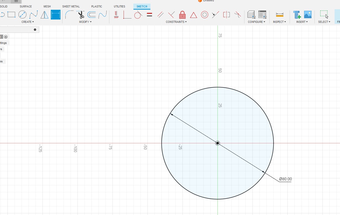
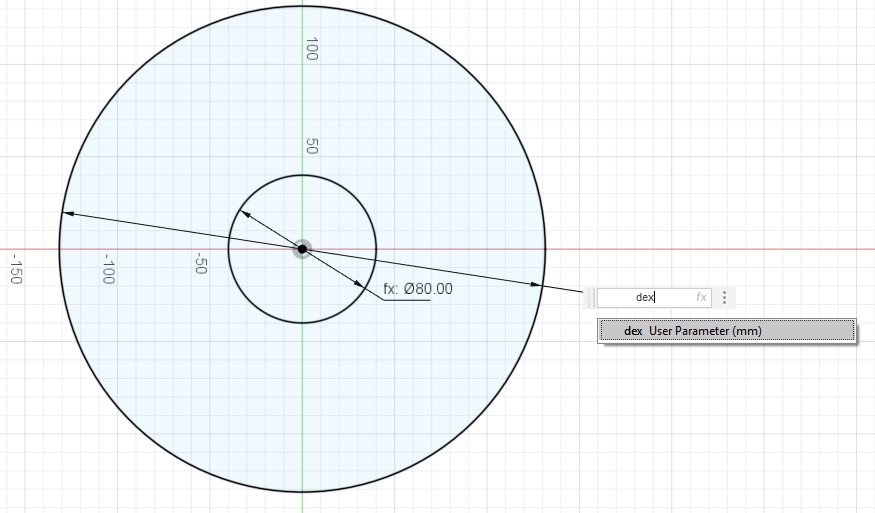
6. As the dimension of the filament spools is not always the same, we change the parameters in the option Change Parameters.
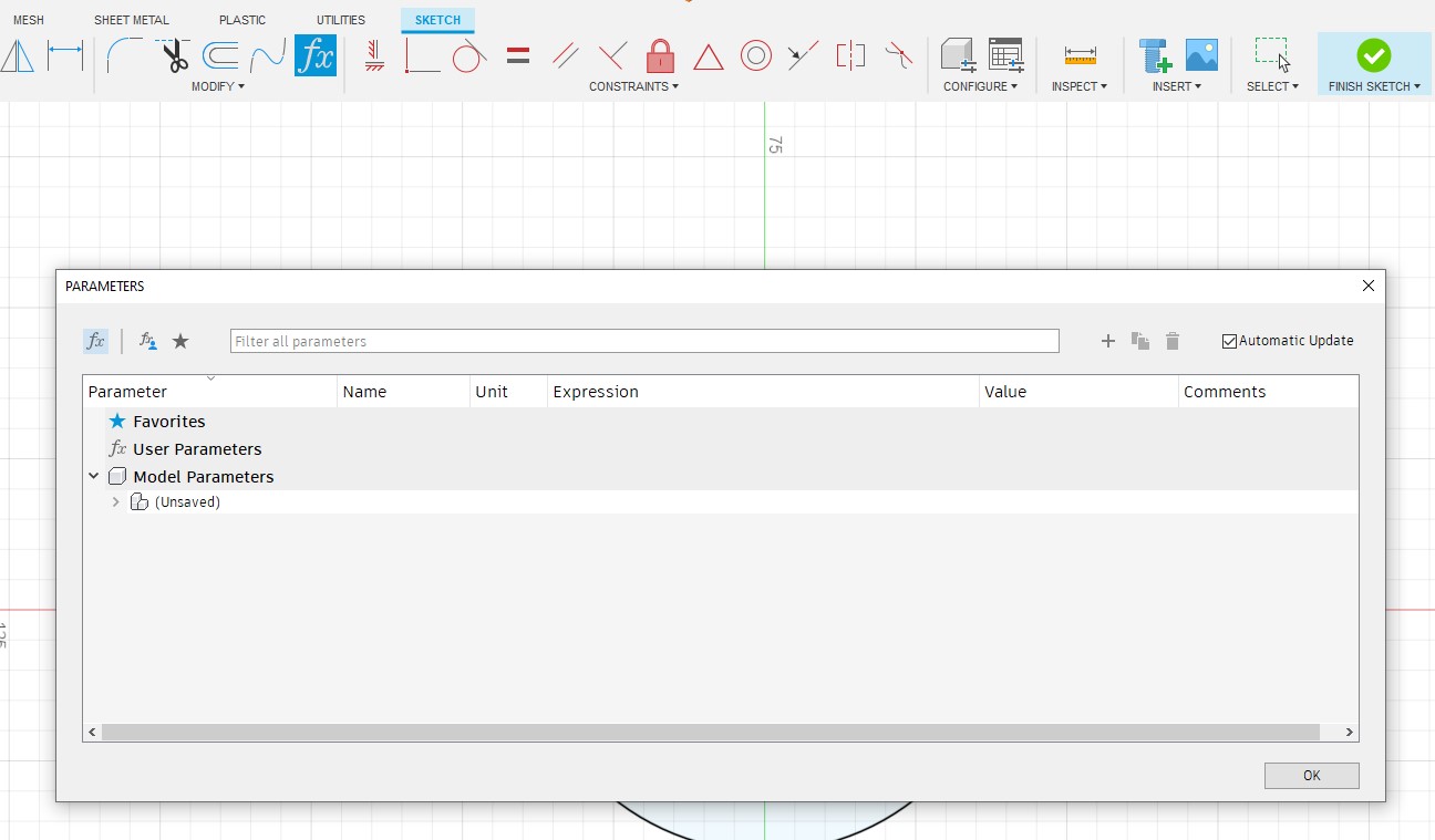
7. Create a new parameter using the "+"" button.
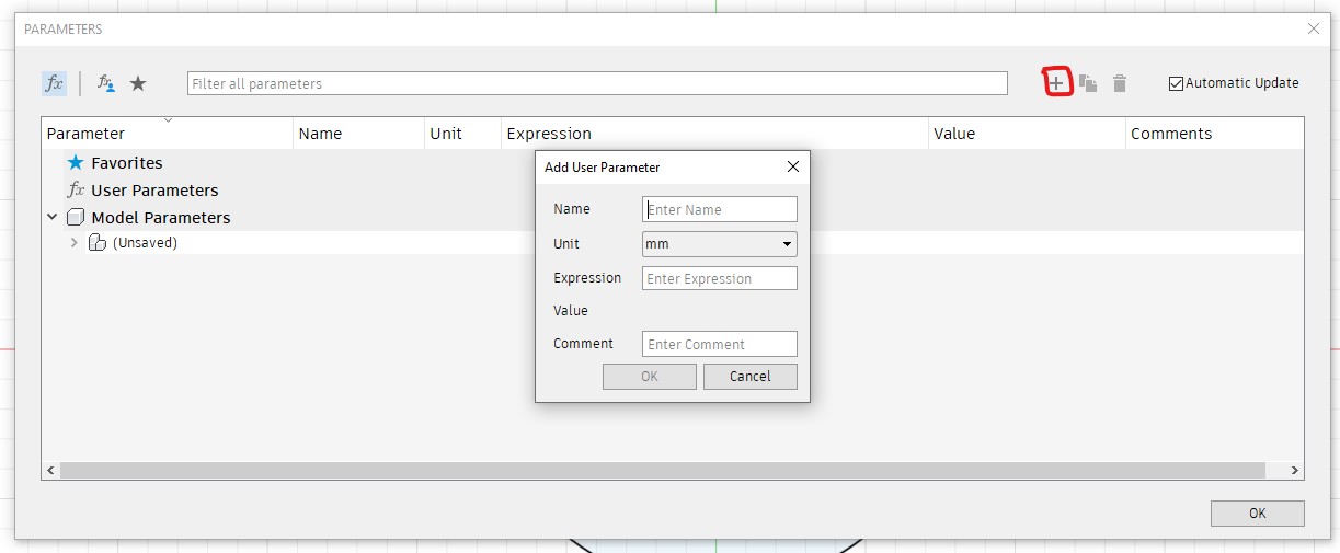
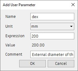
8. We create a parameter for the internal diameter and another for the external diameter.
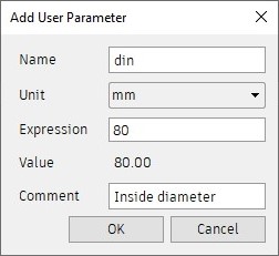
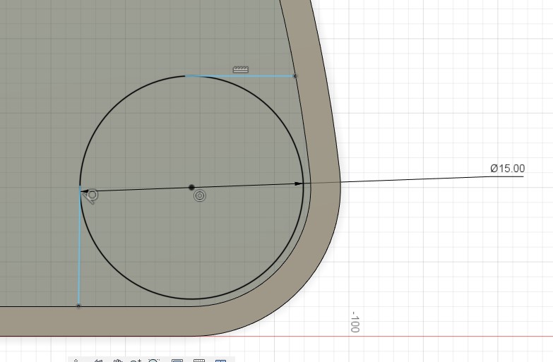
9. We adjust the size of the circle using Sketch Dimension and use the inner diameter parameter.
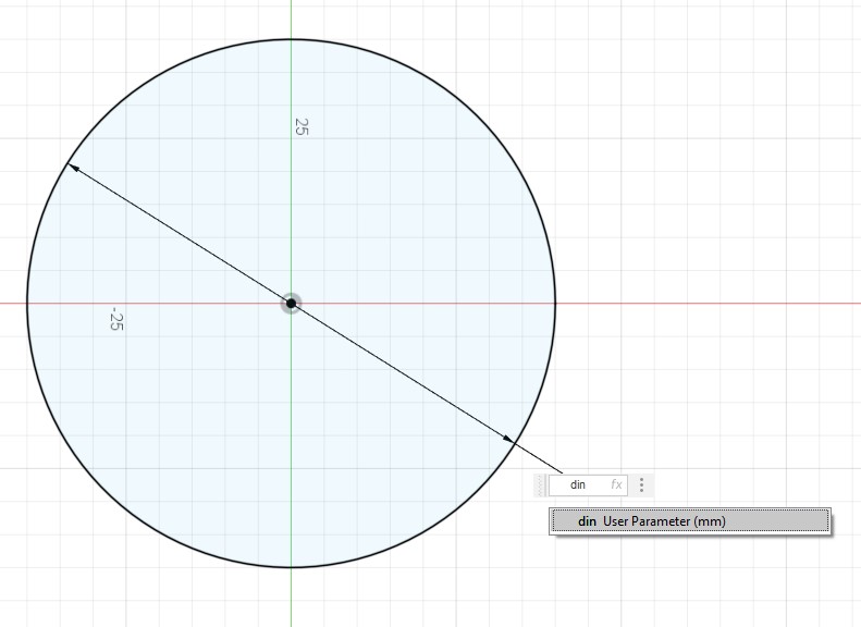
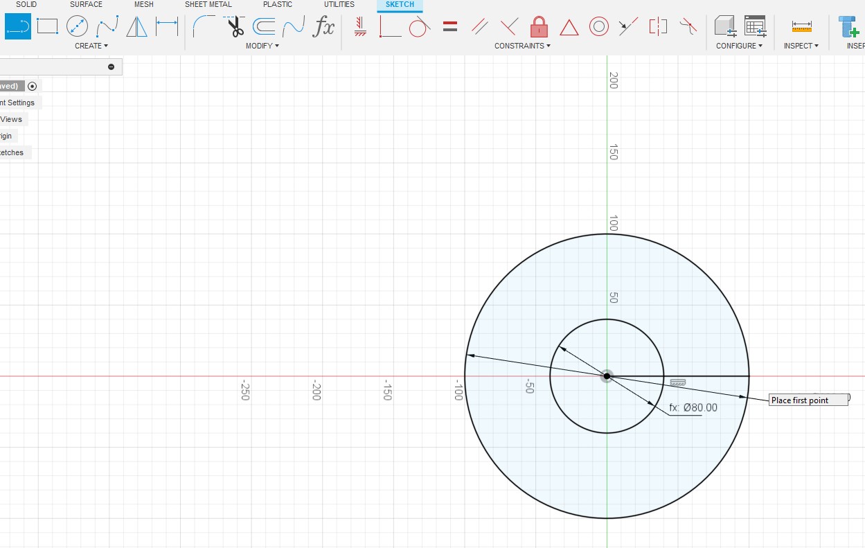
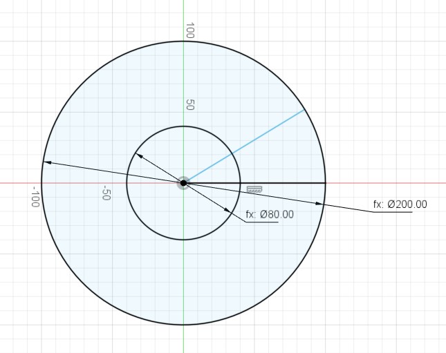
10. Draw another circle and use the outer diameter parameter to adjust the size.
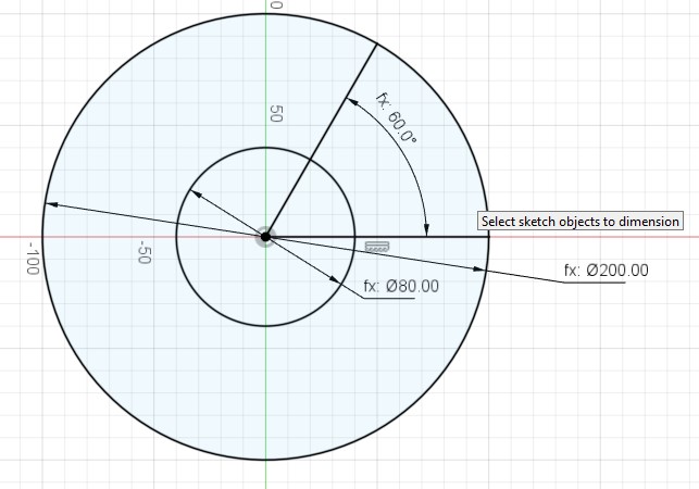
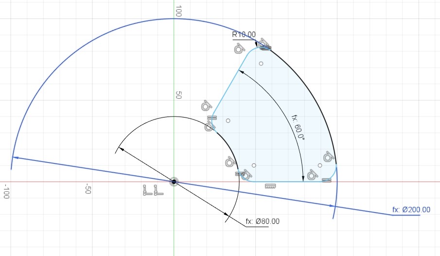
11. Then, we draw a line from the center to the perimeter of the outer circle and another from the center to a point of the outer circle forming an angle.
12. Then, we create a parameter for the number of modules and another one for the angle that we are going to give as a measure.
13. Then, we create a parameter for the number of modules and another one for the angle that we are going to give as a measure.
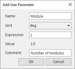
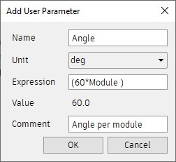
14. Then using the Sketch Dimension option I used the parameter I created Angle.
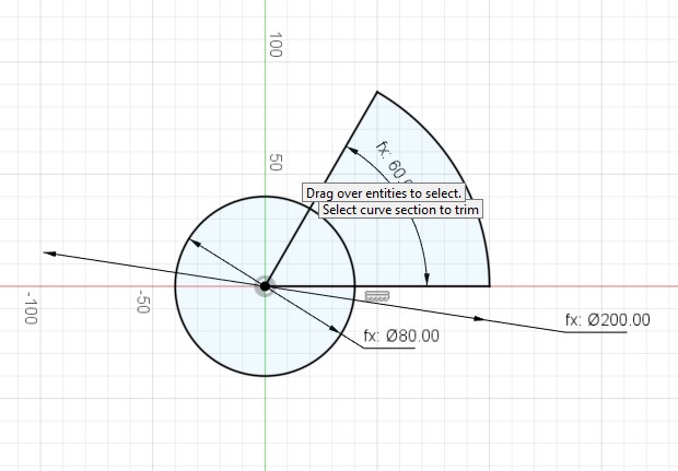
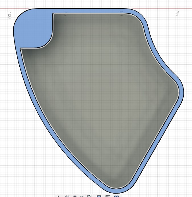
15. Then, with the Trim tool we trim the figure until we have the following:
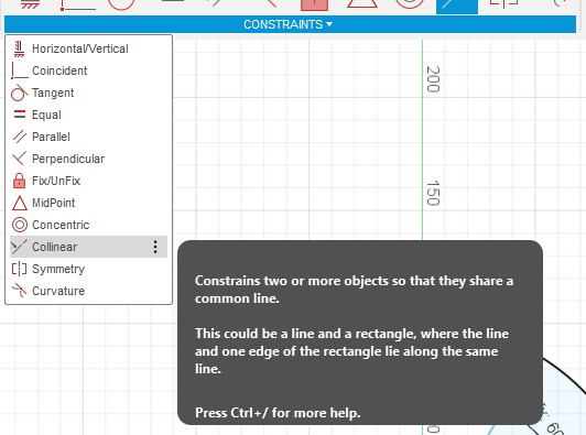
16. After that, we restrict the lines, select the points including the center, as shown in the image.
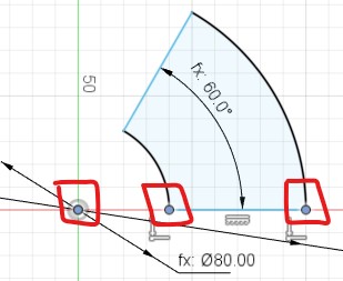
17. To finish restricting we use the Collinear option and repeat on the other side.
18. After, we round the figure with the Fillet tool.
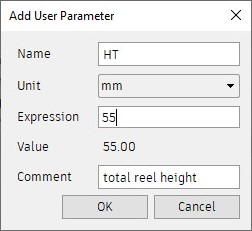
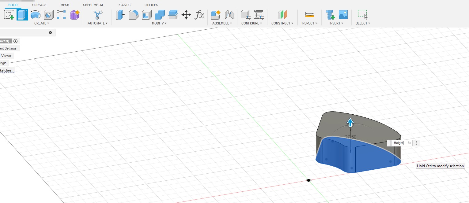
19. We click on the Finish Sketch option and the next step is to create two more parameters, one to define the total spool height and one for the height per box.
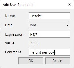
20. Then, we use the Extrude tool and select the figure to change the distance and use the variable Height variable.
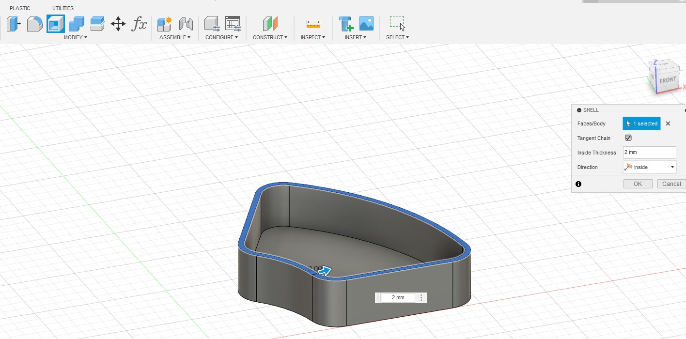
21. Then, we use the Shell tool to remove the top face.
22. Then, select the face below and click on create a new sketch.
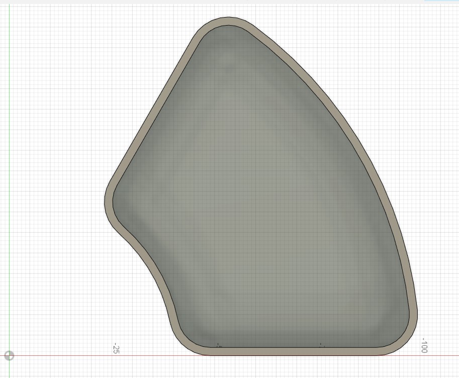
23. After that, we draw a circle, then we select the circle and the line that is in blue color of the figure and we make it concentric.
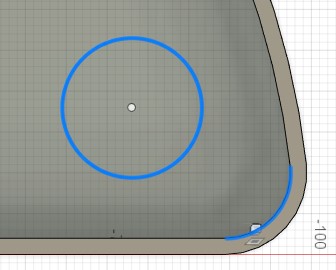
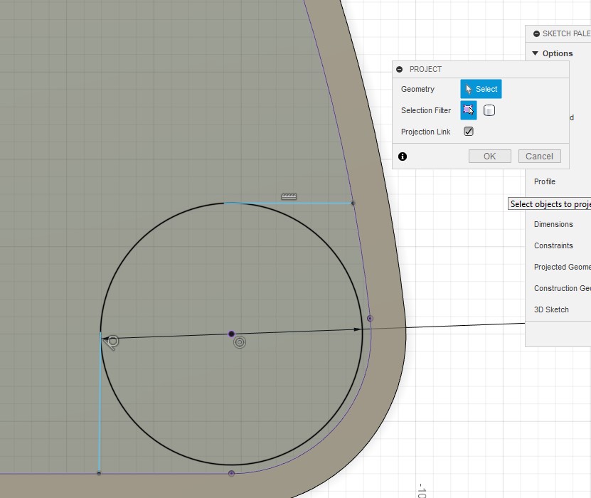
24. We draw two straight lines, as shown in the image:
25. Then we use the Project tool and select the lines shown in purple:
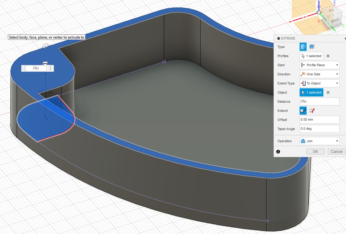
26. We finalize the sketch and extrude the figure with the configuration shown in the image:
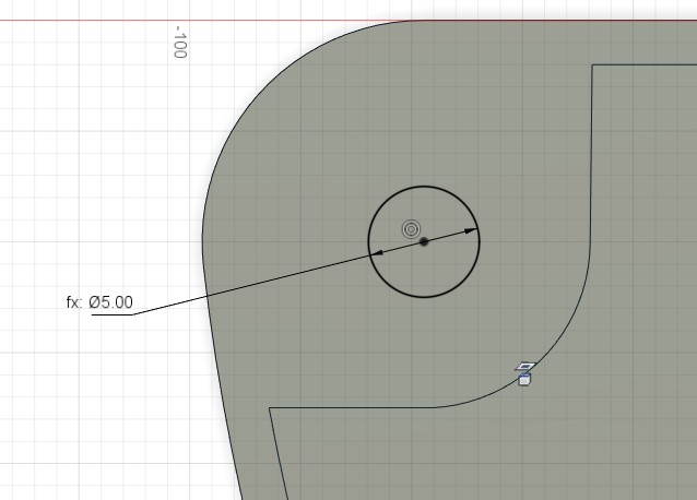
27. Next, we create another parameter for the screw diameter.
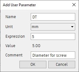
28. Then, we select the face shown in the image and create a sketch.
29. Then, we make the circle concentric with the figure and adjust the diameter of the circle with the parameter we created.
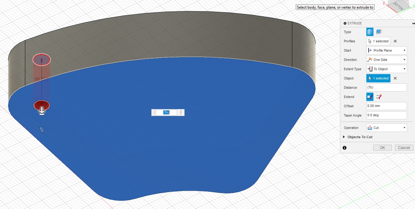
30. Finally, we use the Extrude tool and choose the Cut option and select the bottom side.
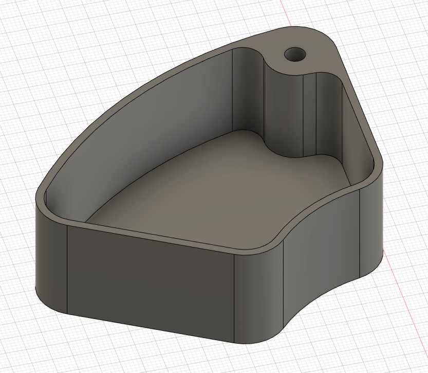
Result:
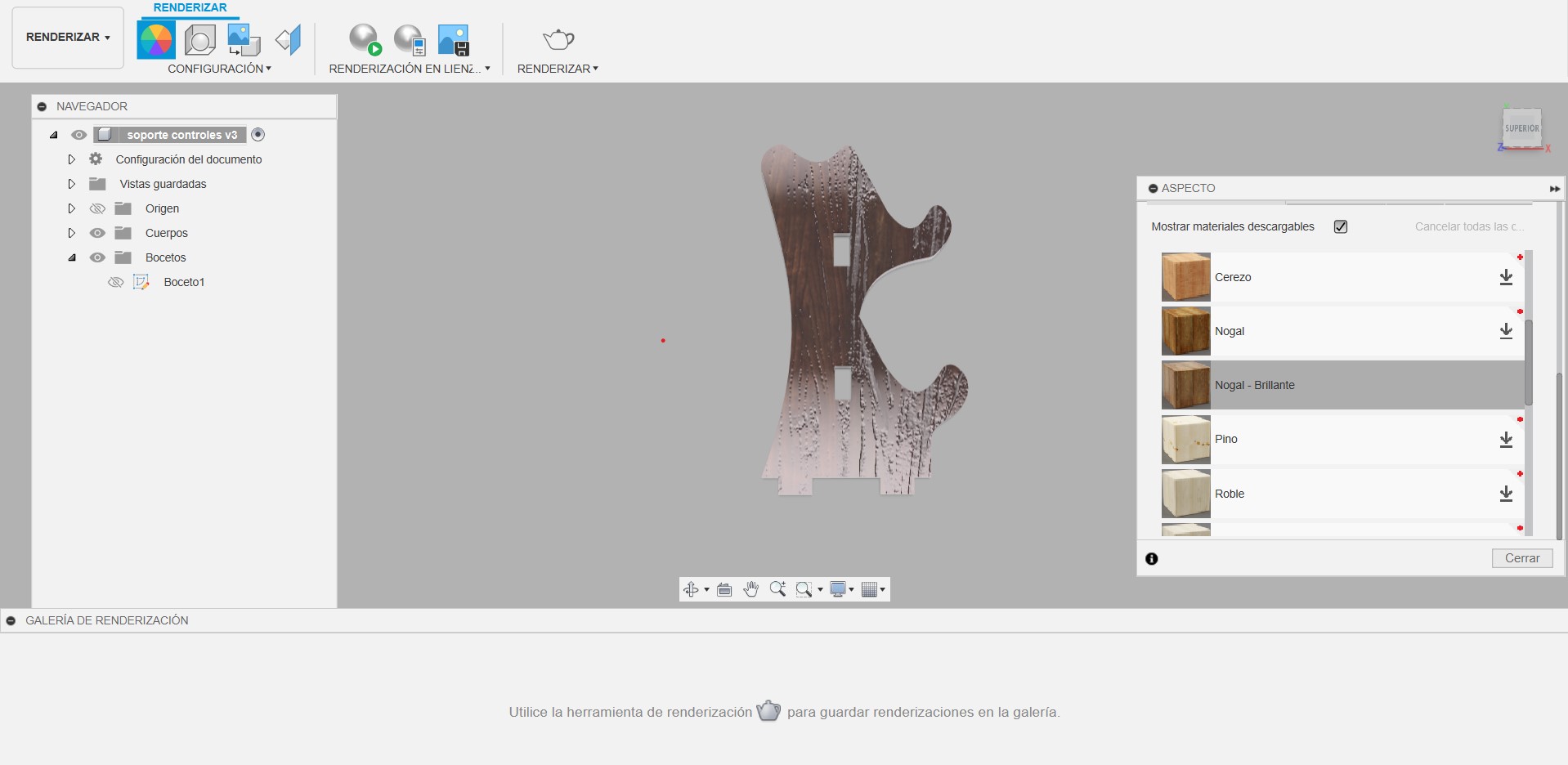
Rendering an object in Fusion 360.
1. Access the render environment
Go to the "render" tab. In the "settings" section, prepare your scene for rendering. Adjust the environment, lighting, and camera as required.
Select different textures or appearances for the model to enhance its visual presentation.
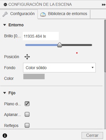
2. Environment adjustment
In "scene settings", customize the environment. Adjust the "Brightness" and "Position" to change how the light interacts with the model. Select a "Background" from the dropdown list, such as "Solid color", and choose your preferred color.
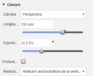
3. Camera settings
Adjust the "Focal Length" to change the field of view. Set the "Exposure" to control the amount of light in the image.
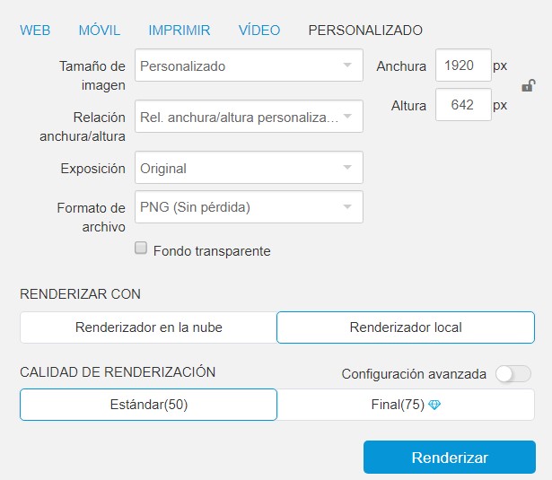
4. Render settings
Click on the "render" option at the bottom. In the settings window, select the "Image Size" and "Aspect Ratio" that best suit your needs. Choose PNG as the file format if you want a transparent background.
Choose between Cloud Renderer or Local Renderer, depending on your preferences or resources.
5. Start rendering
Click Render to begin the process. Fusion 360 will generate a rendering of your model based on the settings you have chosen.
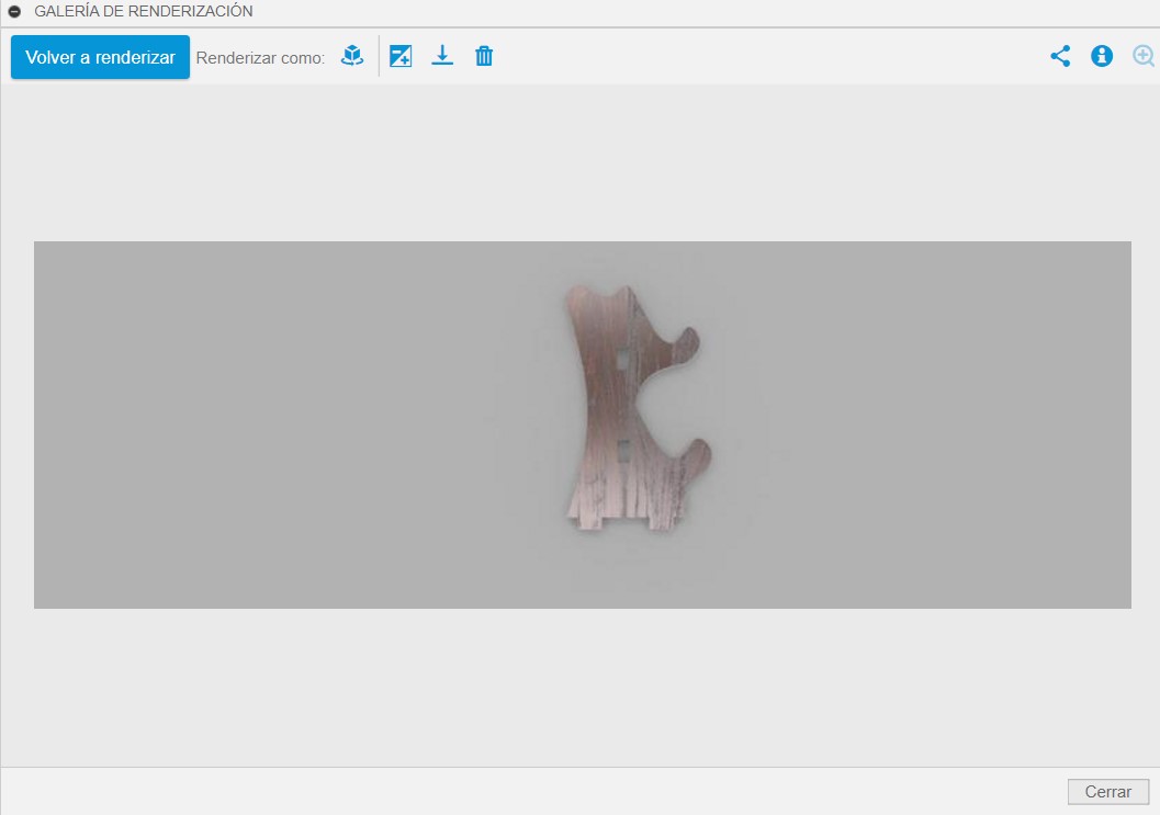
Result:

3D model in SolidWorks
Installation:
For the SolidWorks installation, the technology support office helped me install the software.
Steps to create a figure in SolidWorks:
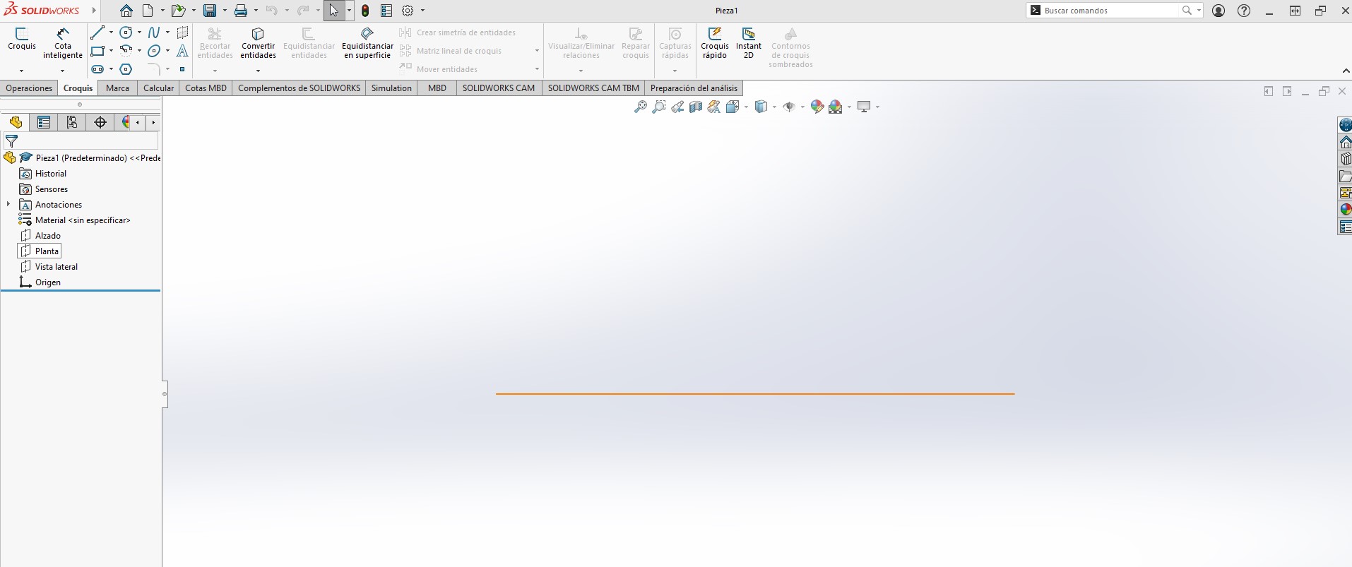
1. We start working in the plan view and click on the Sketch option.
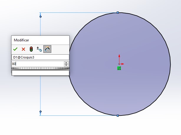
2. Draw a circle from the origin.

3. With the Smart Dimension tool we define the size of the circle.
4. We click on the Extrude Overhang option.
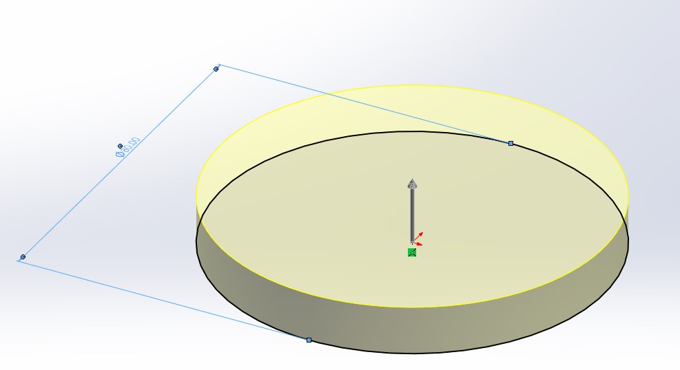
5. We define the depth.
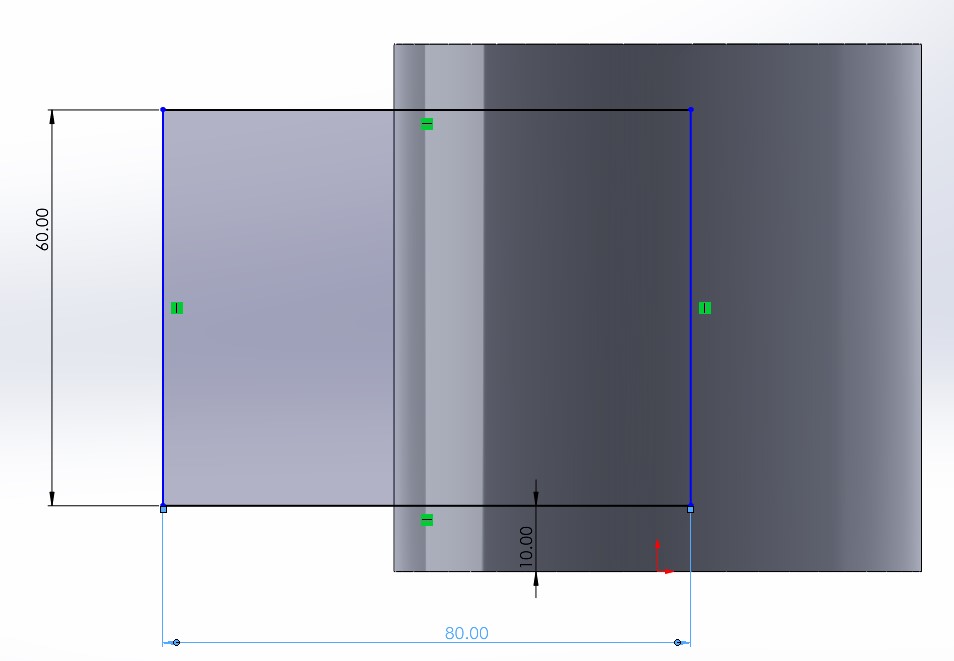
6. We choose the elevation view and draw a rectangle.
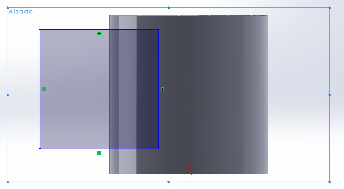
7. We adjust the dimensions using the Smart Dimension tool.
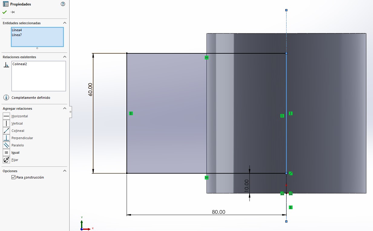
8. We draw a construction line to define the sketch correctly. Then, we select the construction line we drew together with the rectangle and make it collinear.
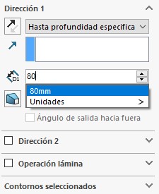
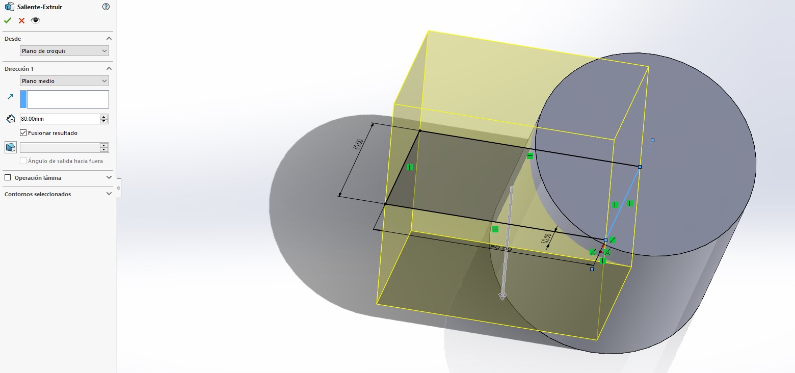
9. Then, select the Extrude tool, choose the midplane option with a depth of 80mm.
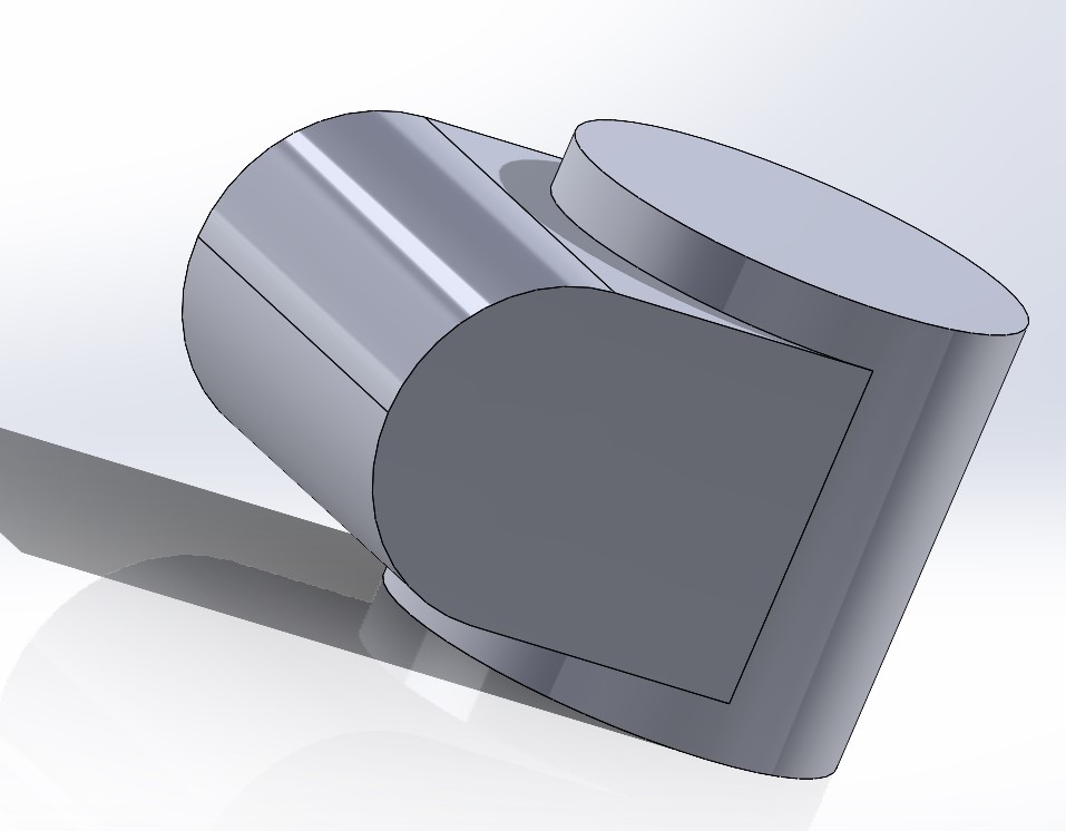
10. Then, we select the Rounding option and apply a radius of 30mm.
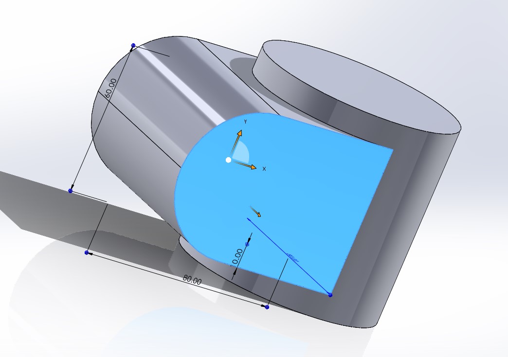
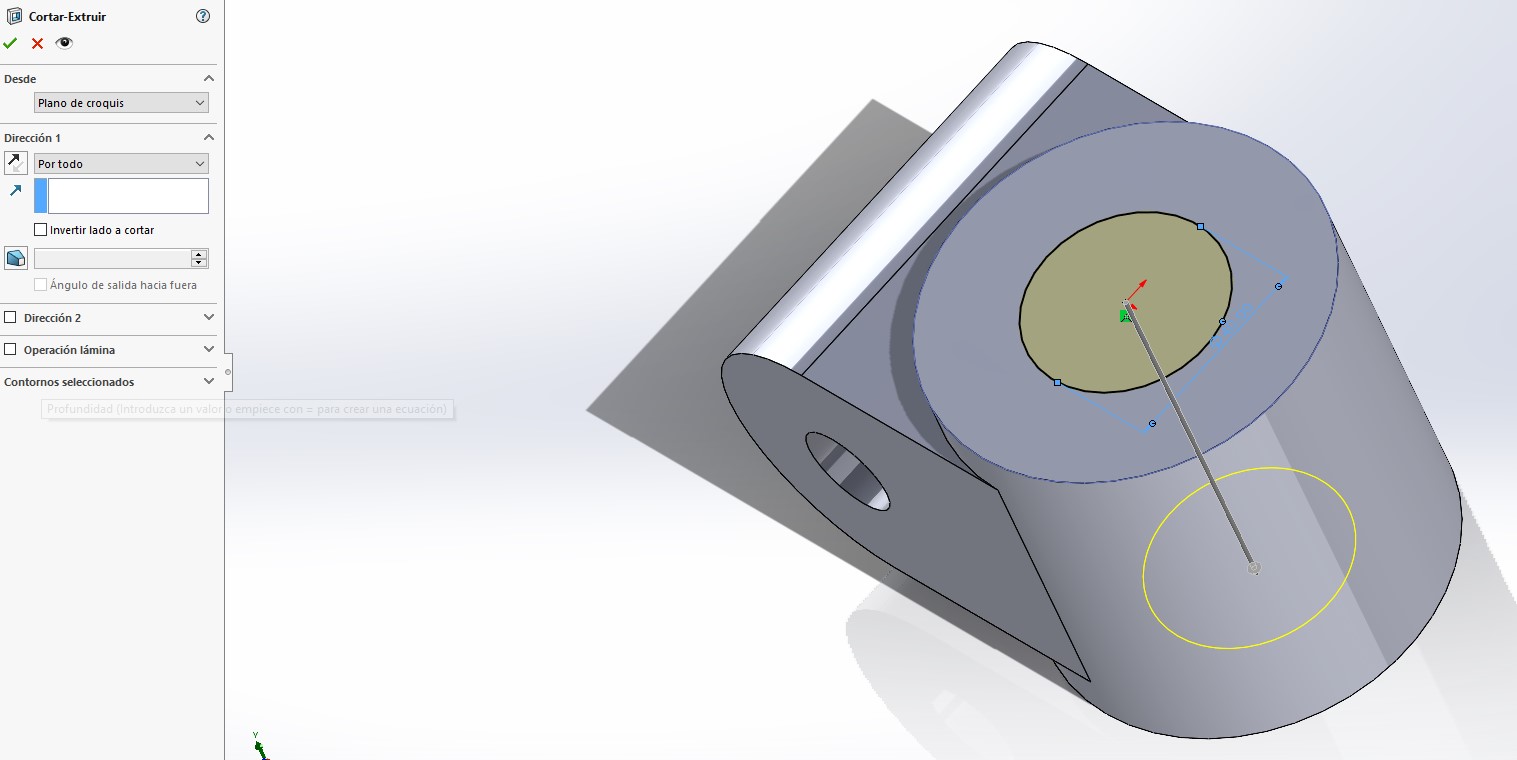
11. We select the face shown in the image:
12. We draw a circle with a size of 20cm.
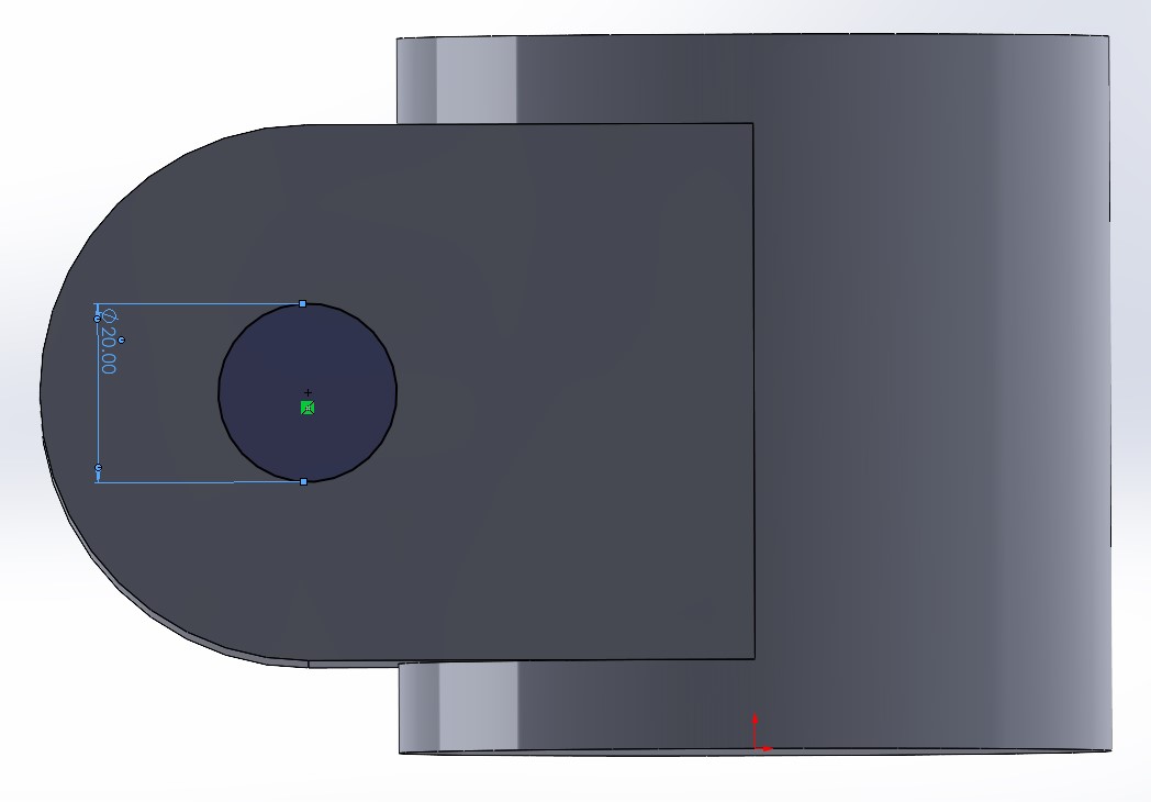
13. Then, select the Extrude Cut tool and choose the option all over.
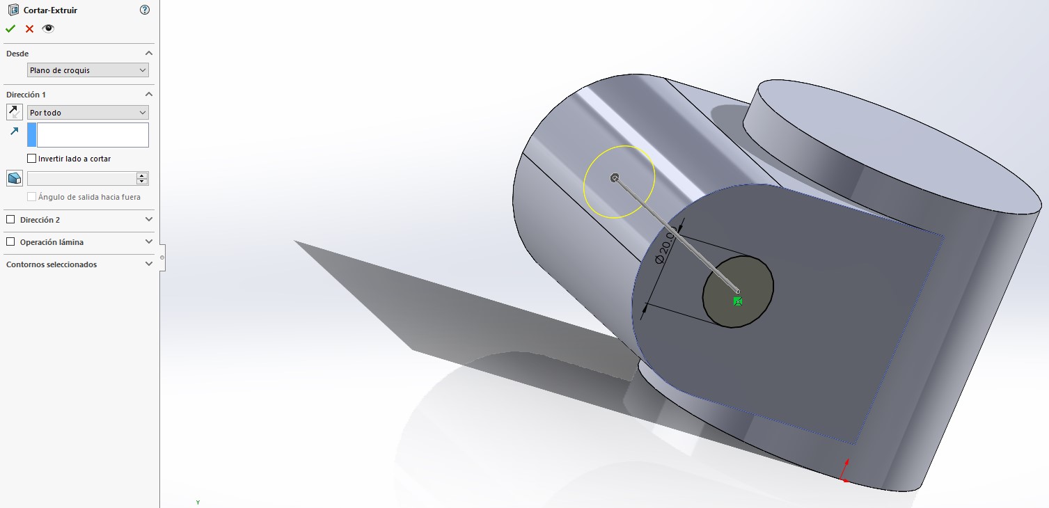
14. Finally we repeat step 12, 13 and 14 on the other figure, as shown in the image:
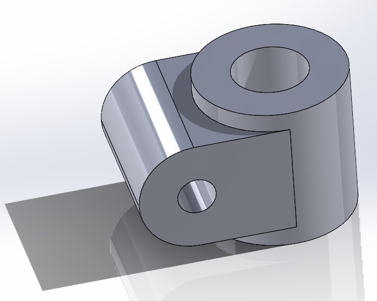
Result:
2D Model in Inkscape
Installation:
- The first step is to visit their website to download the software. Linkscape page.
- The second step is to download the latest version. I downloaded version 1.3.2.
- Finally, we install the software on the computer.
Practice
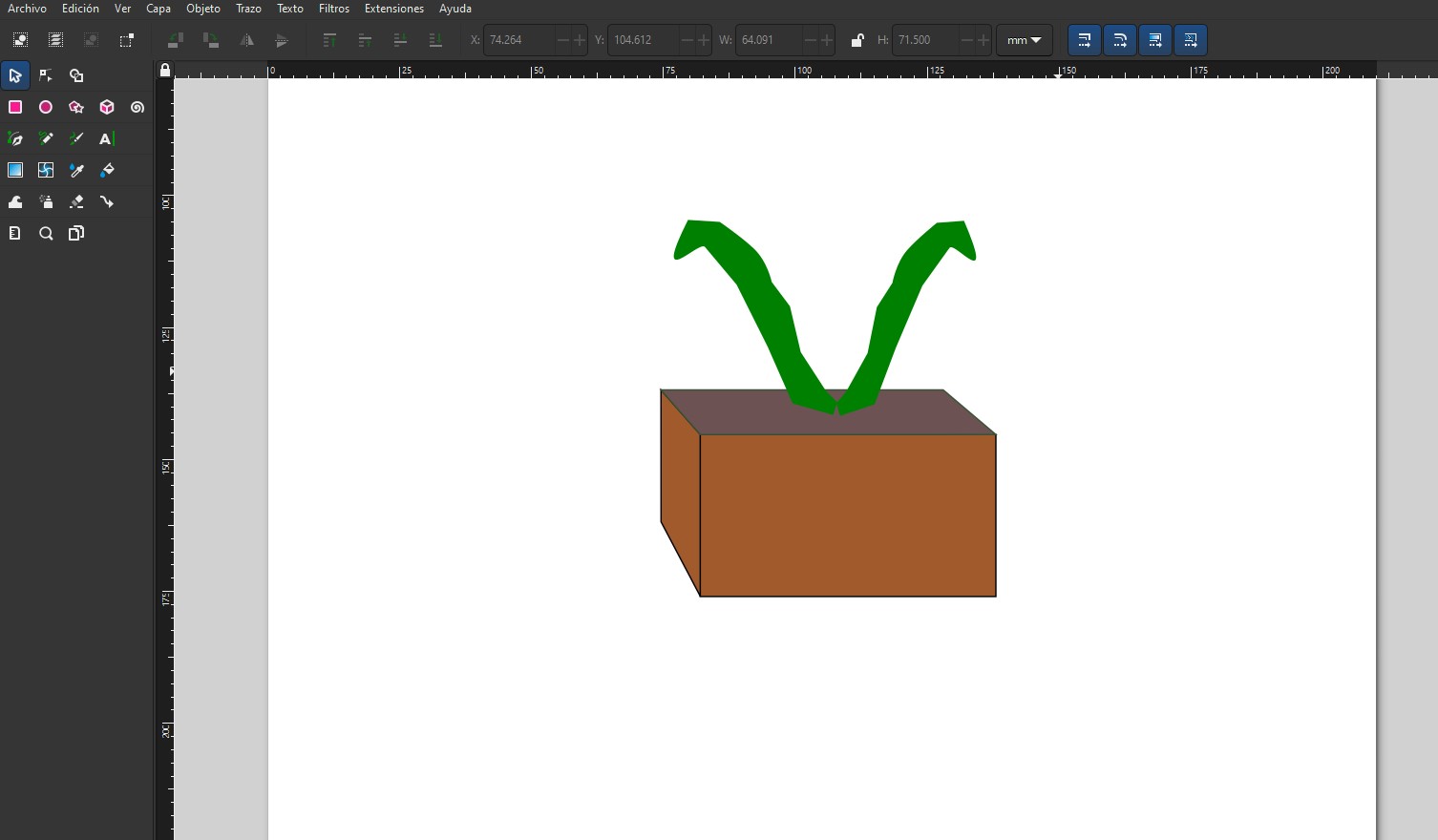
The design I made is that of a flower pot. As this is the first time I used the software, I used simple figures and the pencil to draw.
2D Model in Figma
Installation:
- The first step to use figma is to go to their website. Figma page.
- The second step is to create an account and log.
- Finally, we create a new file to start designing.
Practice
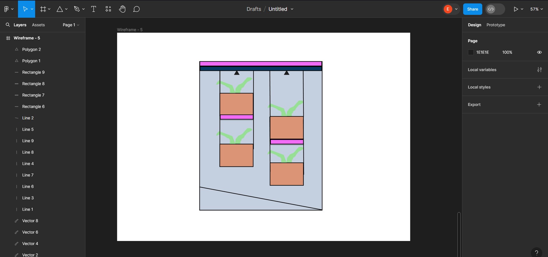
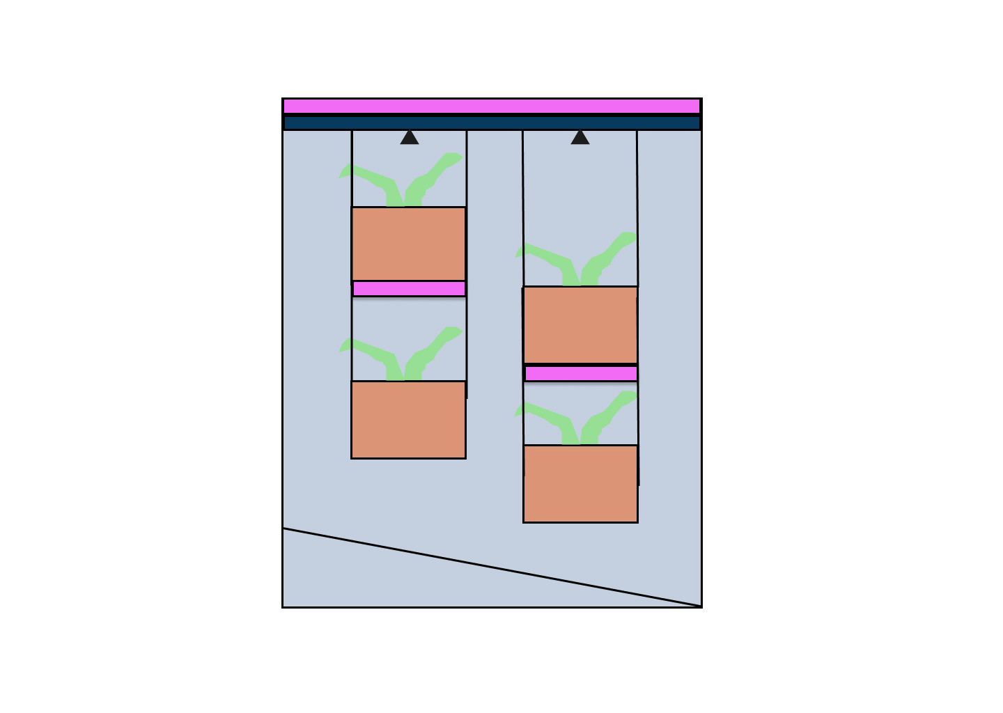
The design I made in figma is an idea of the structure of my smart garden. I used some figma tools like geometrical figures, the pencil to draw and some colors.
GIMP
Installation:
To install GIMP on Windows, follow the steps below:
- You can download it by visiting its page or in the Microsoft store.
- What I did was to install it from the Microsoft Store.
- After downloading the software, I opened the program to use it.
To test this software I wanted to modify an image to turn it into a "drawing". I put it in quotation marks, because it didn't come out quite right haha.
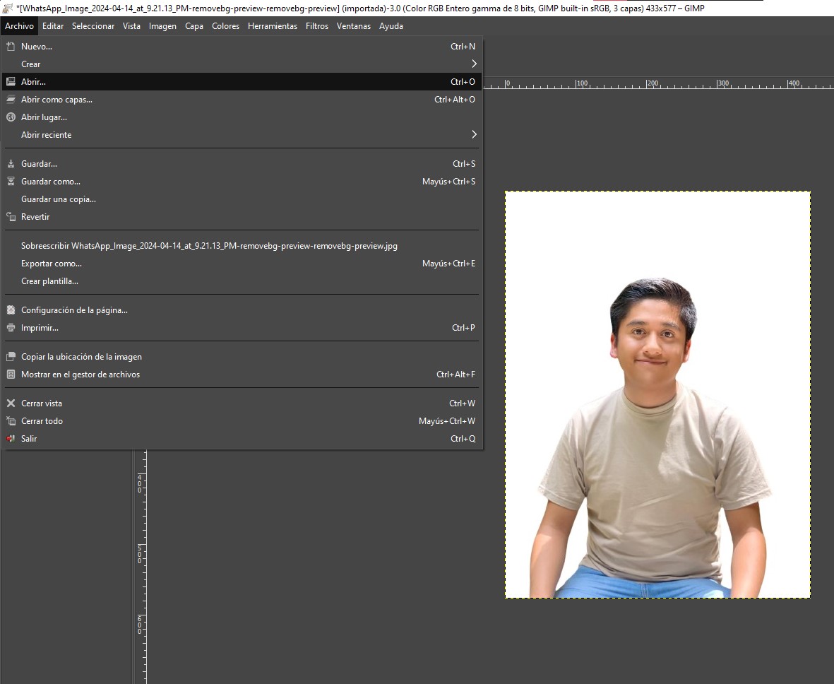
This was the image I used to do the exercise:

First I open the image in GIMP. File -> Open.
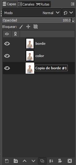
In the lower right corner I duplicate the layer.
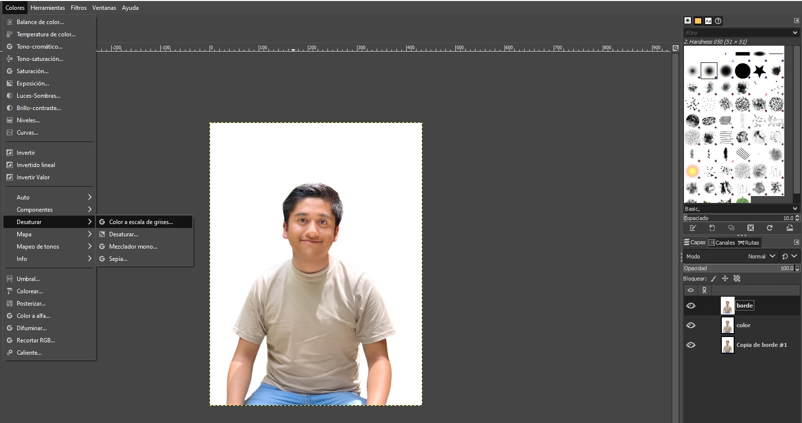
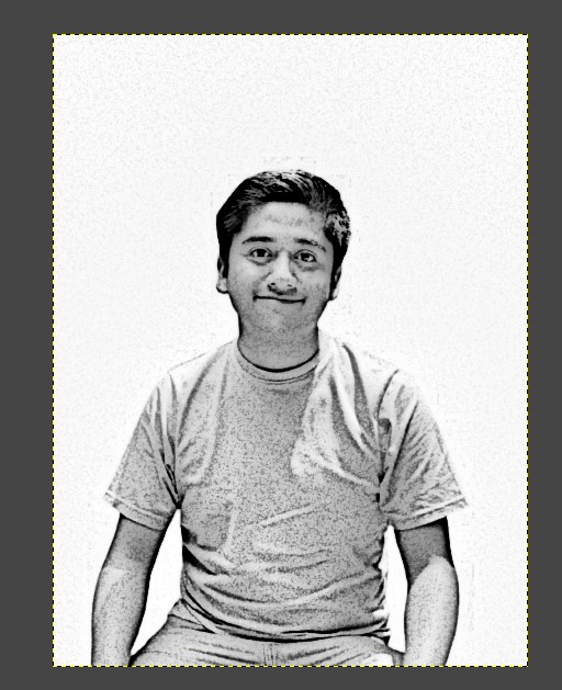
Then I convert the image to grayscale. Colors -> Desaturate -> Grayscale Color.
Result:

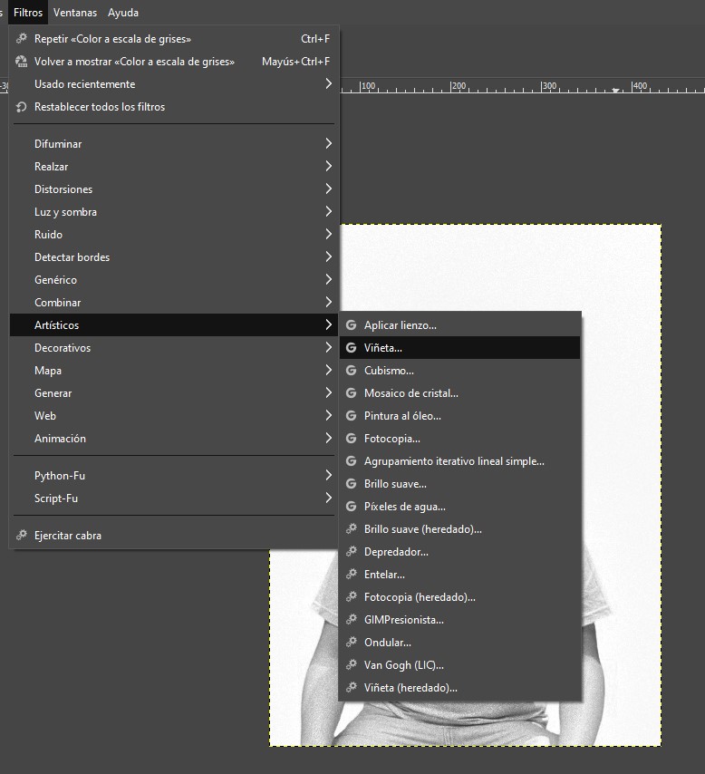
The next thing is to change the filter. Filters -> Artistic -> Vignette.
After playing around with the settings a bit, this is what I got:
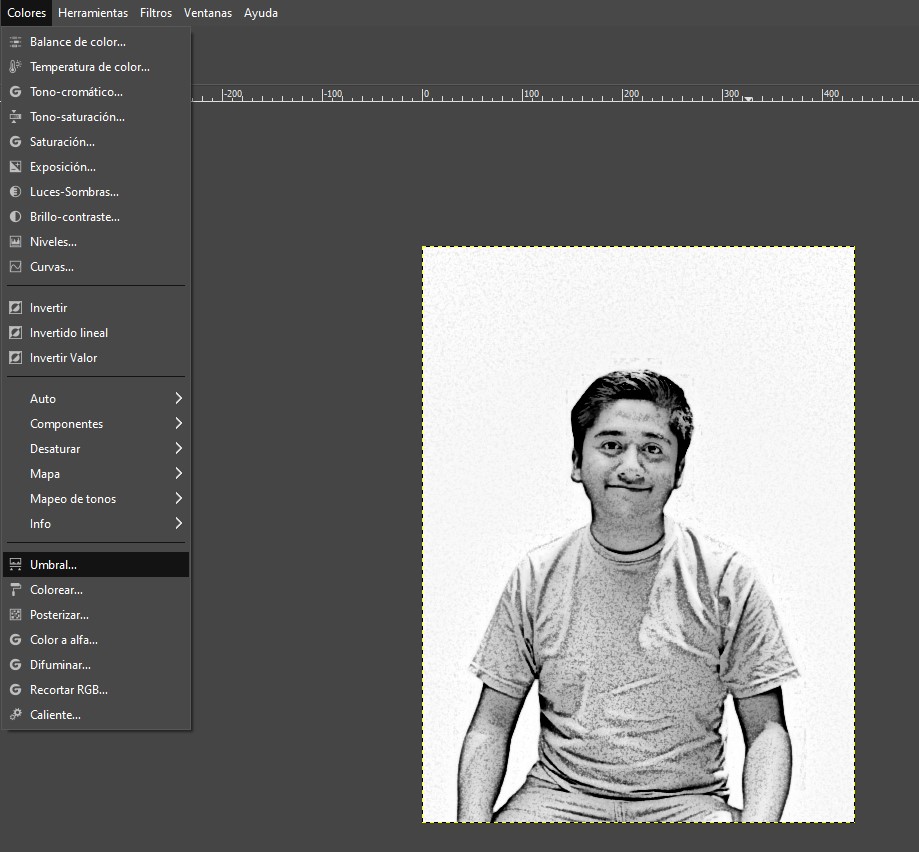
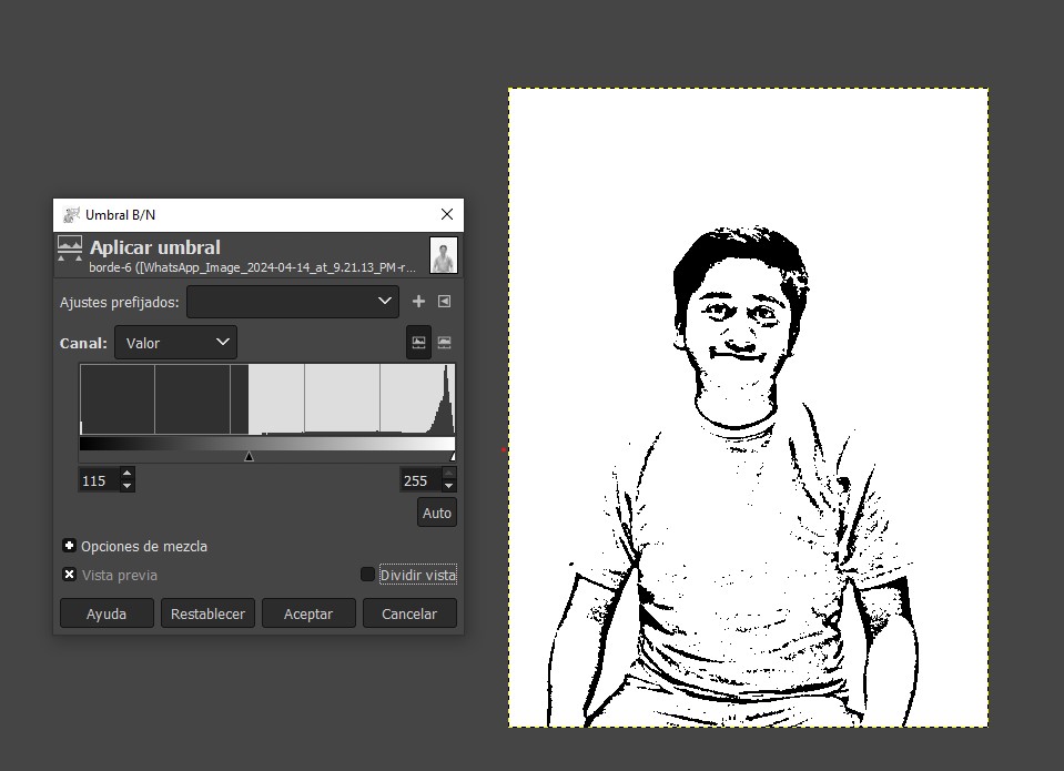
Finally, I go back to colors to change the threshold. Colors -> Threshold.
I play with the settings again and this is the final result: