7. Computer-controlled Maching
Overview
This week's group assignment was to do lab safety training. We also tested the runout, alignment, fixturing, speeds, feeds, materials, and machine tool paths. You can consult the group assignment in the following link.
Figure design in Fusion 360
For the elaboration of my object I used two types of joints to assemble the pieces. All the pieces were made in Fusion 360. It is a software that I have used in other tasks and it is easy to use because of its intuitive interface.
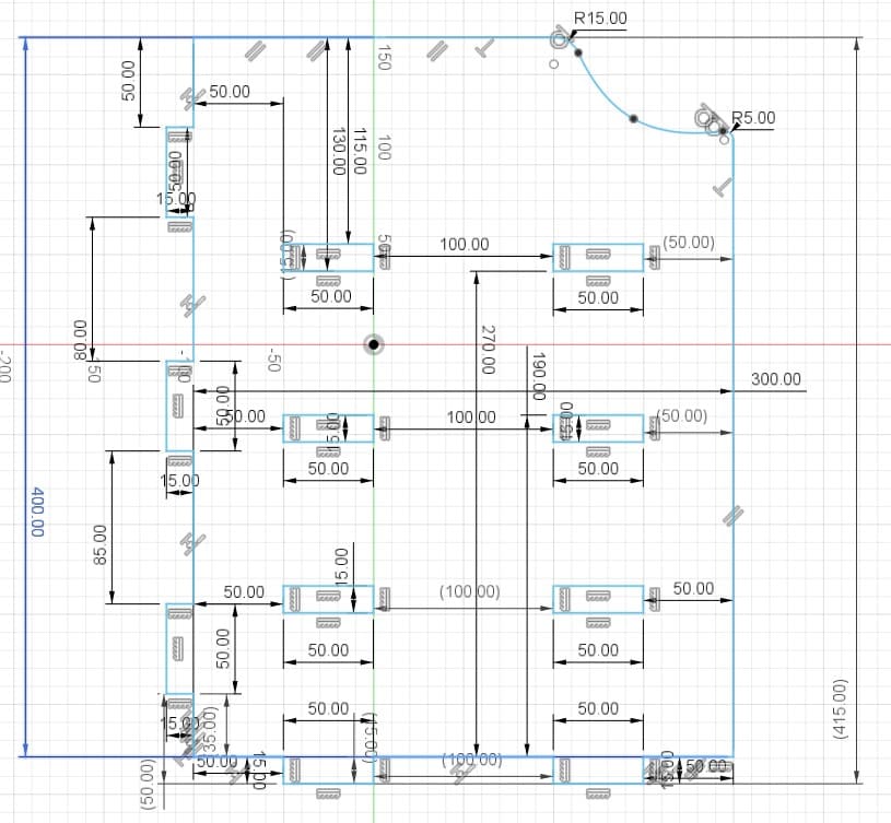
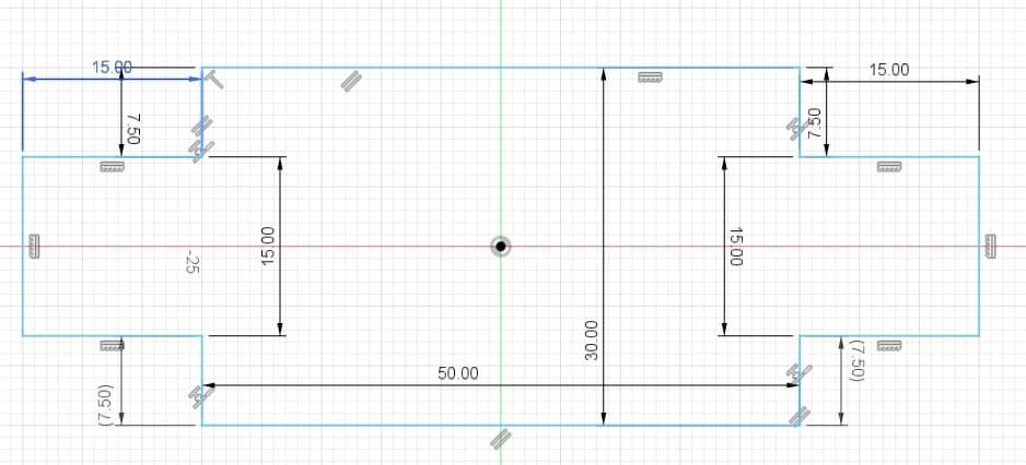
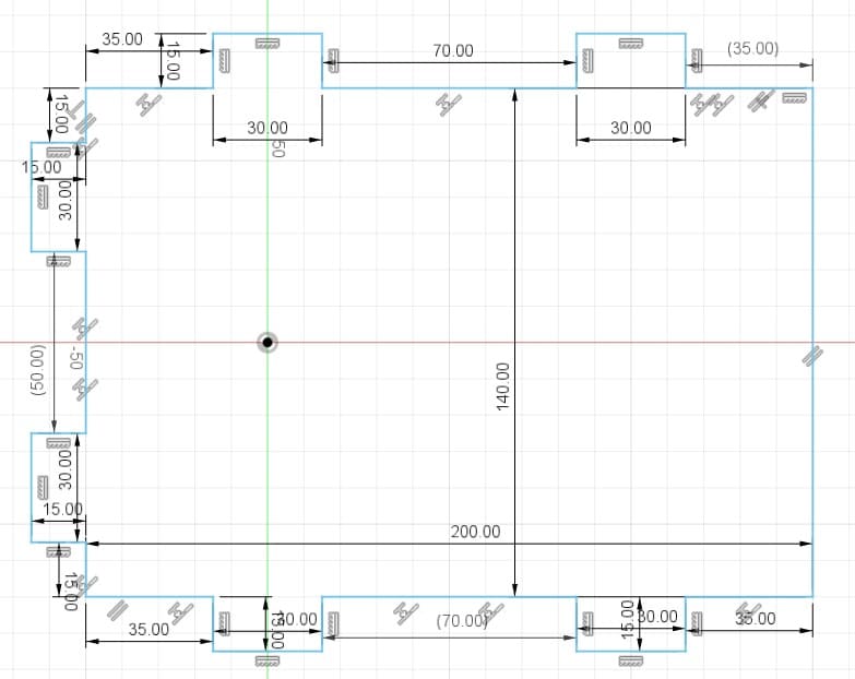
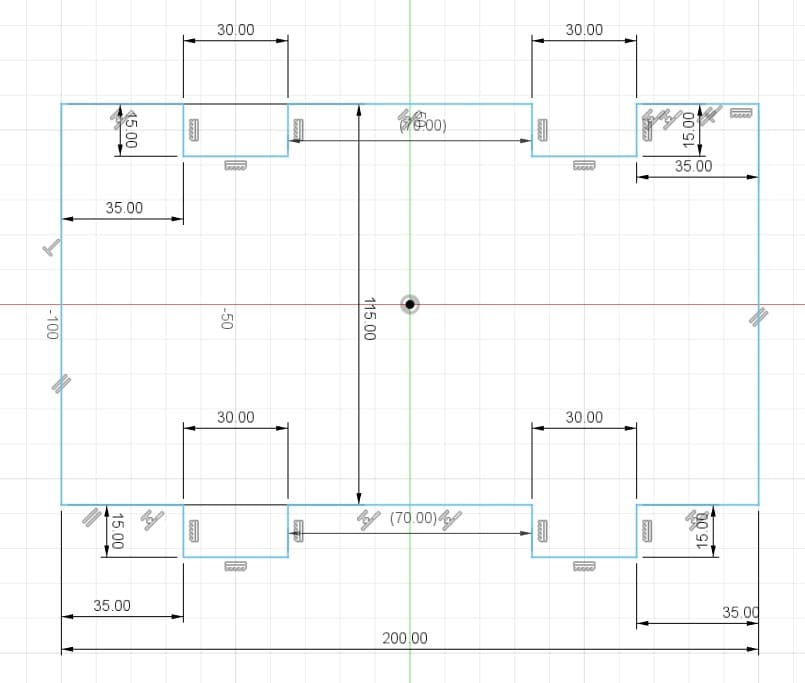
Boxes
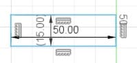
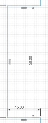
The boxes are the spaces or holes where my pieces will be assembled. For their design I considered the thickness of the material I was going to use. In my case, I used 15 mm MDF. So the width of my boxes are 15 mm. For the length I tried different sizes, 30 mm, 40 mm and 50 mm.
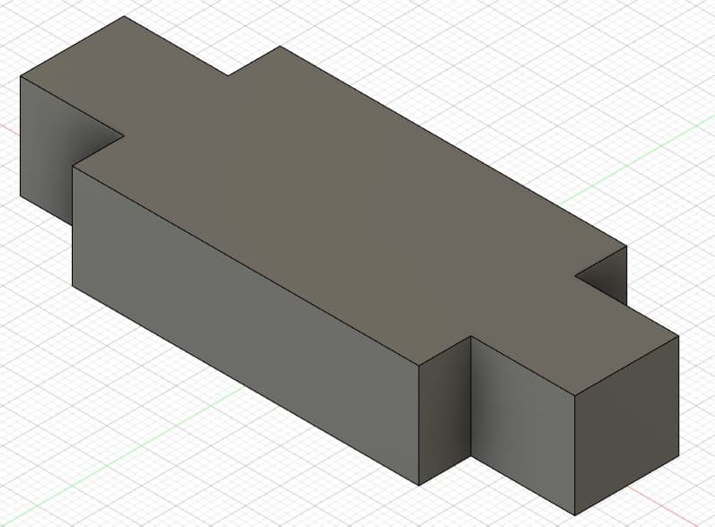
Dowel
The dowels are the joints to assemble the boxes. The length depends on what size I put in the box (30, 40 or 50 mm) and the width is 15 mm, which is what the MDF measures.
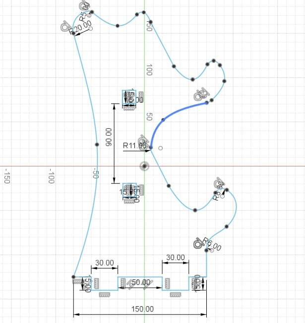
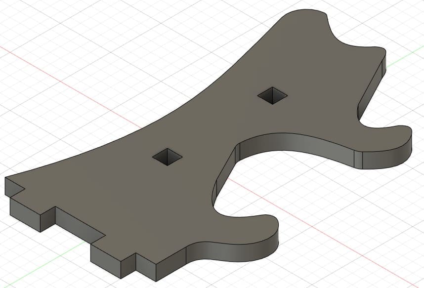
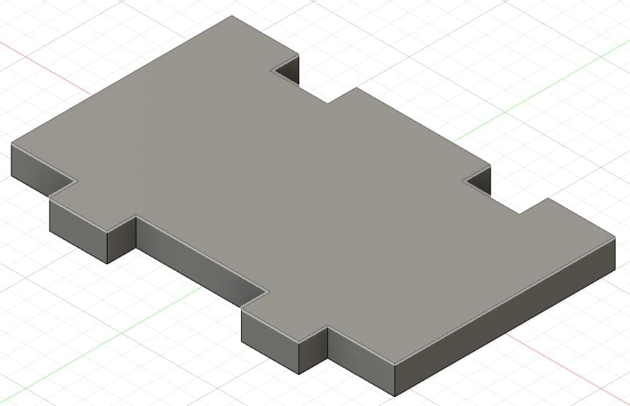
Pieces in Fusion 360
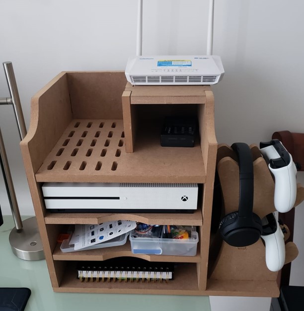
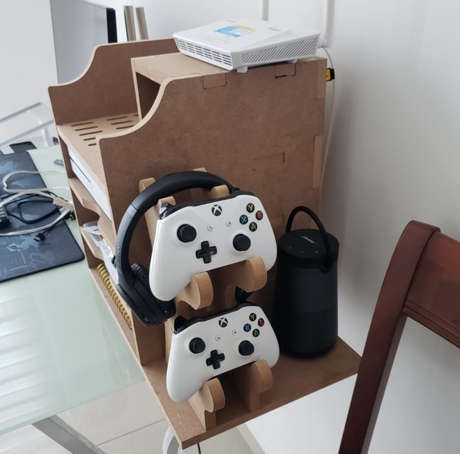
The object I made is a desk shelf. I made it with the purpose of improving the space on my desk, since it allows me to store my things in a better way. The design also allows to accommodate an xbox one s, it also includes supports for controllers and headphones.
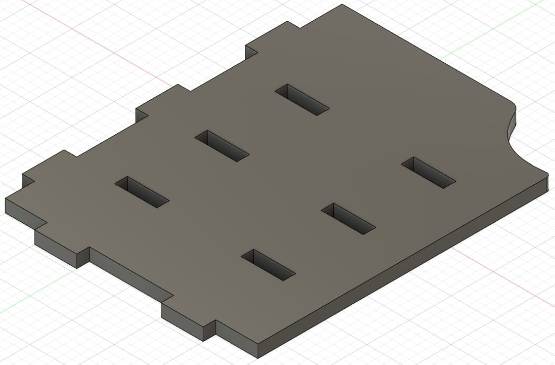
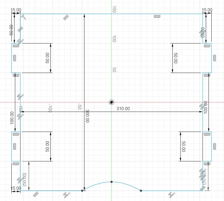
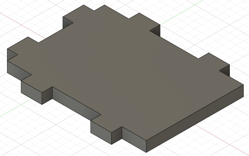
Piece 1: first wall of the shelf.
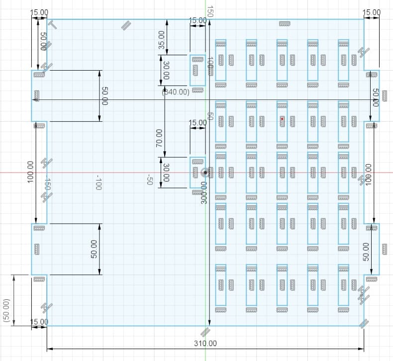
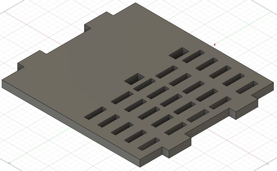
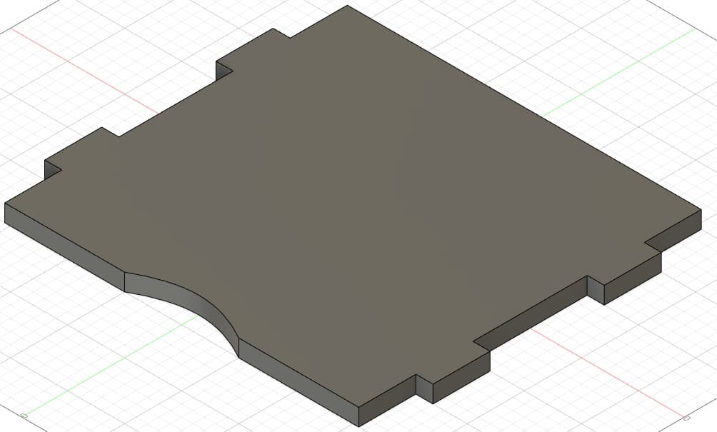
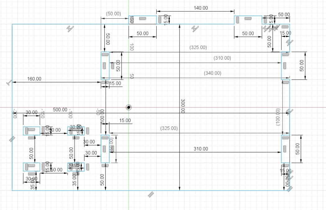
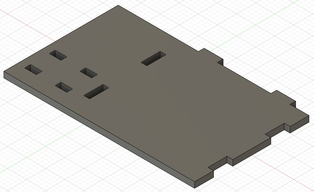
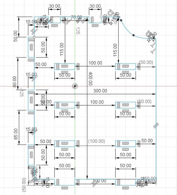
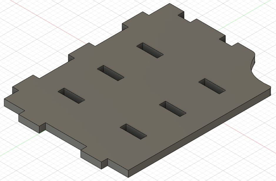
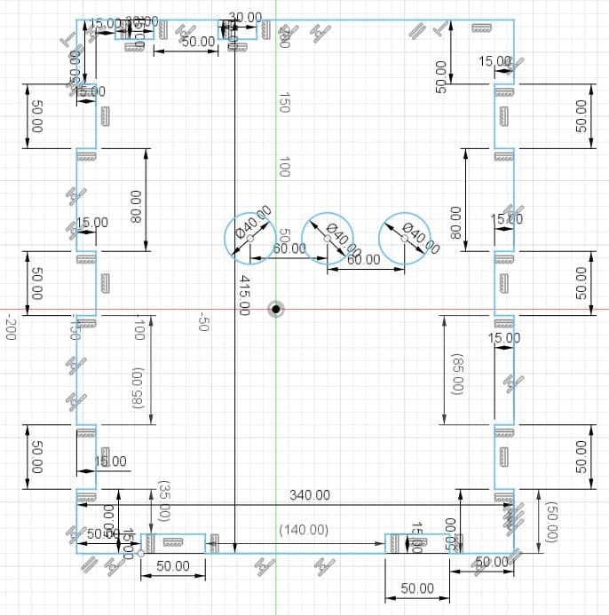
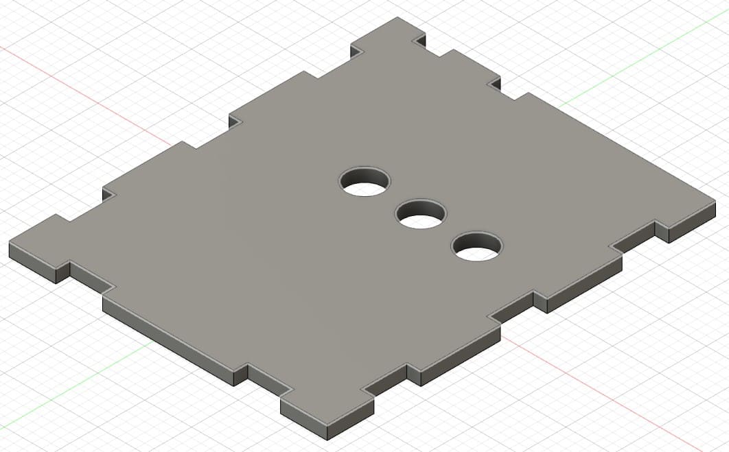
Piece 2: shelf with holes for xbox ventilation.
Piece 3: shelf for the other shelf levels.
Piece 4: shelf base
Piece 5: support for controls and headphones.
Piece 6: piece to join the previous brackets.
Piece 7: ceiling to join pieces 2, 9 and 10.
Piece 8: second wall of the shelf.
Piece 9: this part is assembled on piece 2.
Piece 10: third wall, back part.
Exporting files
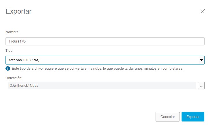
After finishing the design of my parts, I continue to export all the files in .dxf format. For this we go to Files, choose the Export option and select the files we want to export.
VCarve CNC Software
V-Carve is a CNC design and machining software used primarily in sign making, engraving, and woodworking,
offering specific tools for 3D carving projects. This software is highly appreciated for its intuitive
interface and its ability to generate efficient and high quality cutting paths. V-Carve allows users to
import 2D and 3D models, create complex designs using a wide range of drawing and editing tools, and generate
optimized toolpaths for a variety of machining processes, including carving, engraving, and milling.
You can consult the V-Carve website at the following link.
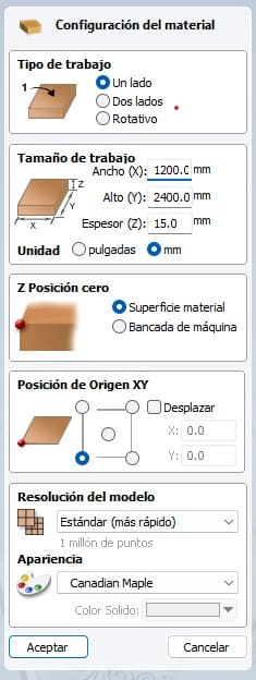
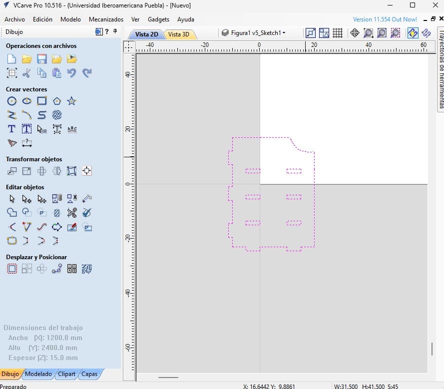
After exporting all the files, we will use the V-Carve software. To use the software you must have a license. Fortunately, the university has this software on several computers. So the first step was to find a computer that had the software. The second step was to open the program, when I opened it the following image was displayed, where I changed some parameters according to the material I was going to use. The material I used is a MDF with a thickness of 15 mm, a width of 1200 mm and a height of 2400 mm. These were the parameters I used in this first stage.
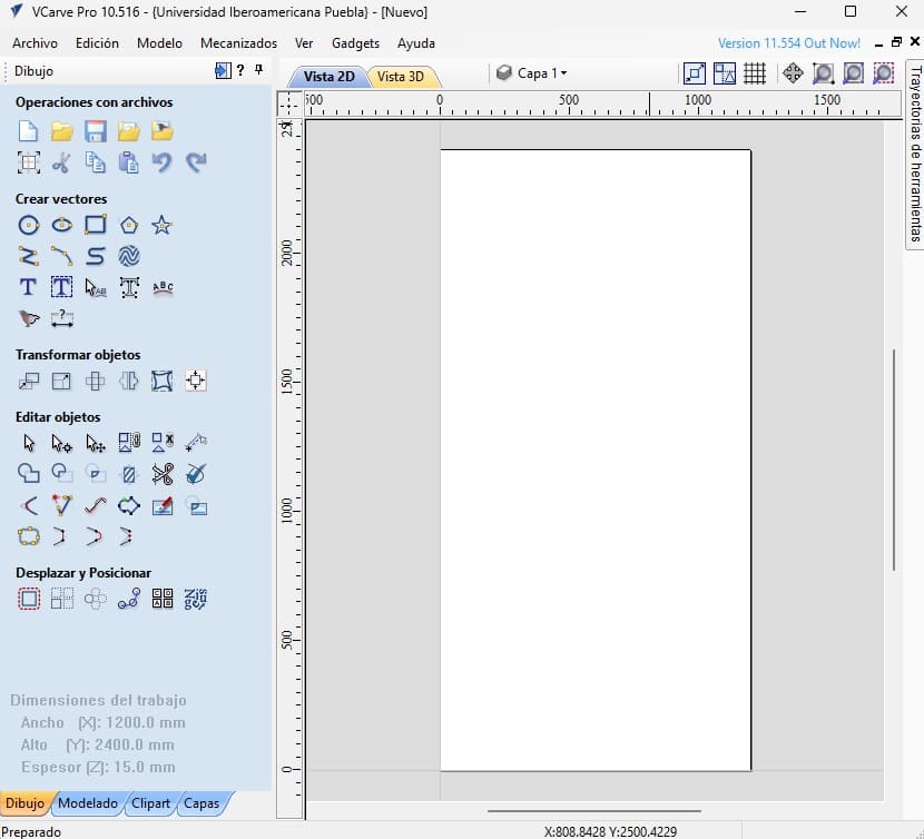
After confirming the changes I made, the menu shown in the image with different tools was displayed.
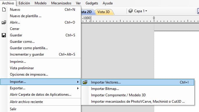
The next step is to import all my design files in .dxf format. To do this, we select the Files option, then the Import option and finally the Import Vectors option. And so we do it for each file.
When importing a file, the piece will appear as shown in the image:
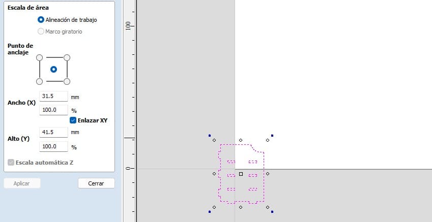
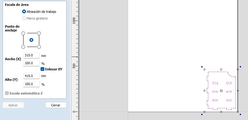
I had some problems with my files, they were too small so I had to use the Scale Selected Objects option.
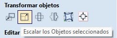
When selecting the option, change the width value from 100% to 1000% in width. To adjust the scale properly I also selected the XY Link option.
Next, I put the piece in the blank.
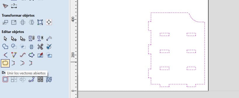
The next step was to use the Join Open Vectors tool. This tool is used to join the lines of the parts. First we select the whole figure and then click on the tool.
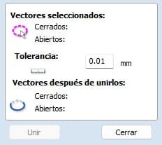
When clicking on the tool, a small menu will appear, where we will select the tolerance, in my case I used a tolerance of 0.01 mm. Then, click on join vectors.
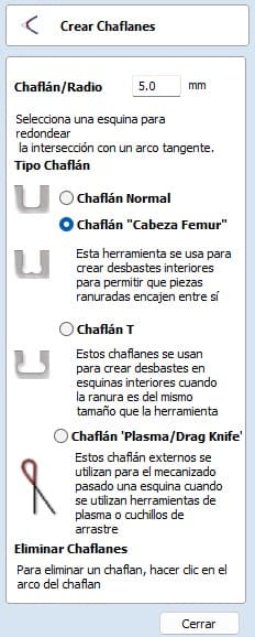
After doing the above. We will adjust a few things on our parts. We will create interior roughs to allow the slotted parts to fit together. There are two types, Dog bones and T-bones. Both work and serve the same purpose. This is done by the tool that is used, being circular we have to leave a little extra space so that the space to fit fits well according to the design that was made. The one I used was the Dog Bone.
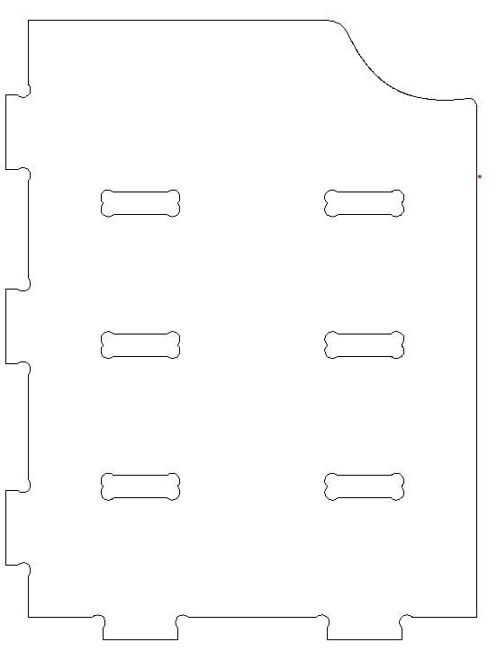
This is the resulting piece after making all the modifications.
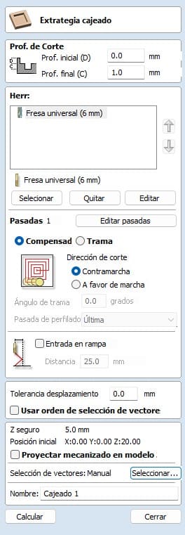
Next is an important step, we have to create some small joints to the pieces, this way we make sure that they will not move when cutting. This is done because the machine vibrates a lot. The next step is to use the tooling tooling strategy. With this tool we can adjust the cut, for the boxes the cut is inside while for the outside part the cut is outside.
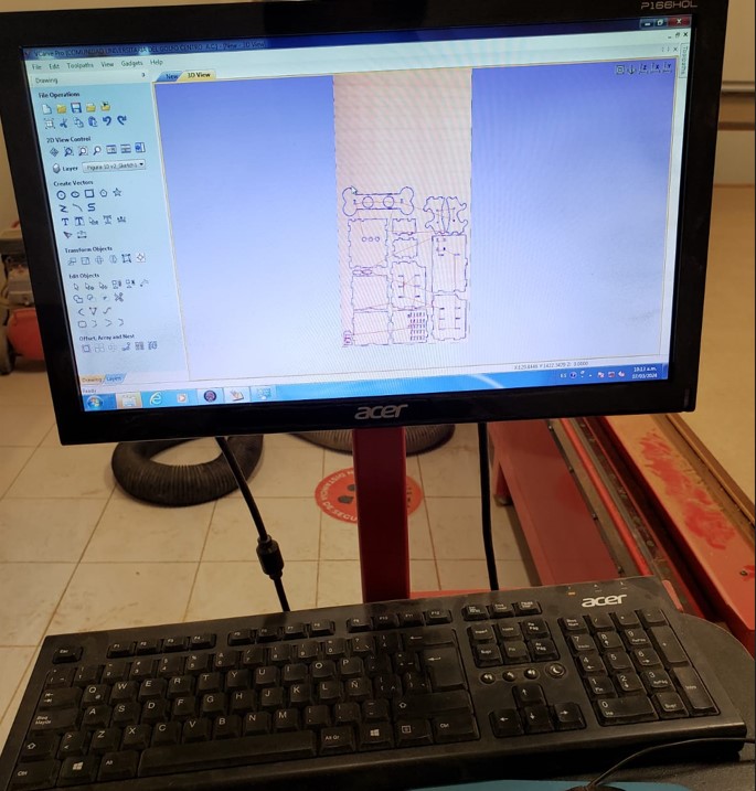
Finally, we switch to the 3D view to visualize all the images and test how they will be cut. First we will cut the inside of each piece, to finish with the outline of each piece. To export the file, we need to open File to export the file and when we export it we get a txt file.
Before using the machine
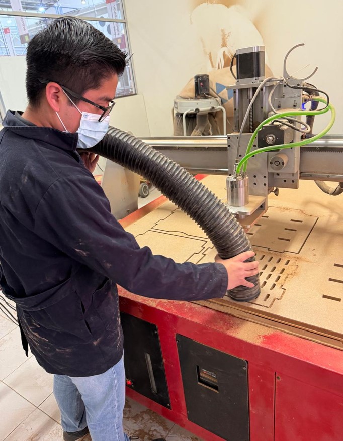
Before using the machine, we have to enter with the proper protection. Gown, safety glasses, boots and mouth cover. In addition, it is important to have located the extinguishing gas and the university medical service in case of an accident. This in order to protect ourselves.
Router
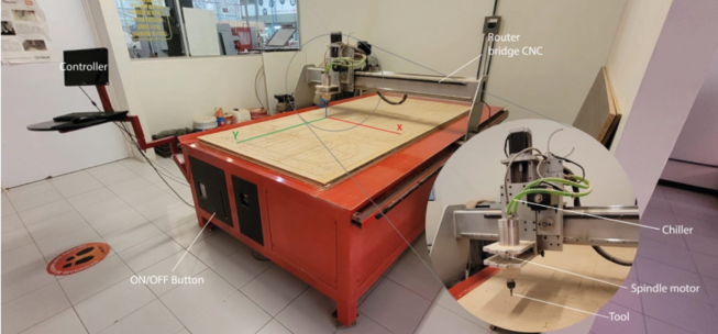
The router I used is the one shown in the image. I can't put the model, as this router was manufactured at the university, not purchased.
To use the router, we need to use software to control the machine. This software is called AR2400. At the university we have two types of router. The one I used is one that is made by the university, so I can't put the link to the software page.
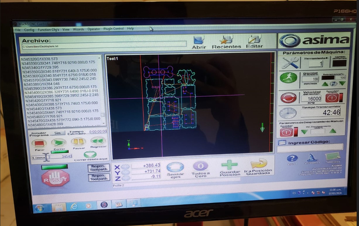
Inside the software we import the file given to us by V-Carve. In this software we can adjust the three axes of the machine, here we can control the cutting tool. In addition, we can visualize the parts in real time while they are being cut.
After making the adjustments, we have to place the material on the router bed. The material I used is a 15 mm thick MDF. To adjust the material, we have to put some nails, so that the MDF does not move.
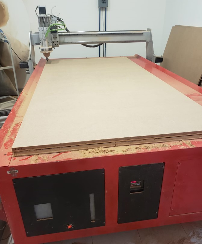
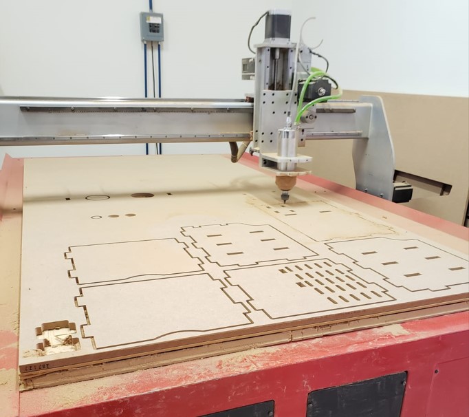
After setting and adjusting the material, we adjust the axes in the software and give start. The following images are some pictures I took of the router.
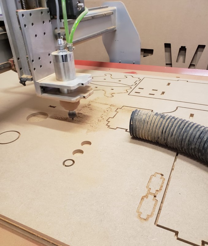
The machine releases a lot of material residues, so it is necessary to vacuum constantly, this avoids getting too much dust.
Here is a video of the machine cutting. (The video has audio)
One of the problems of being so long in the machine, is the noise it makes, in the video you will hear the noise made by the machine.
The solution for this problem is to use headphones to reduce the noise.
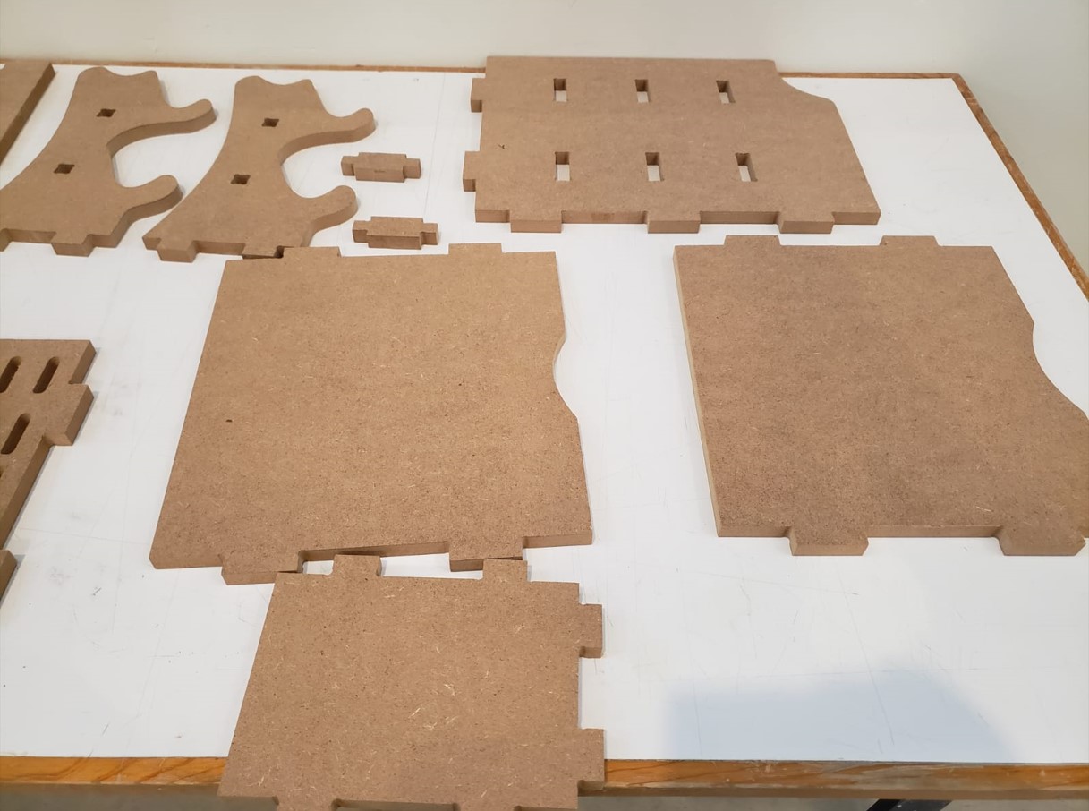
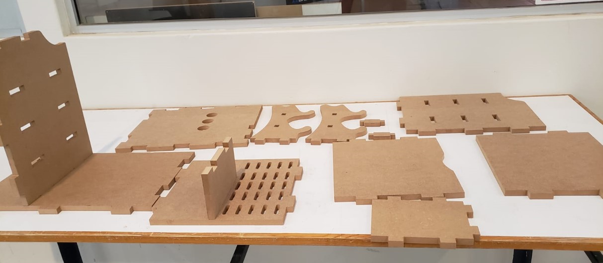
When the machine finishes cutting, I finish vacuuming well and then remove the nails. Then I start to remove the pieces from the material. These are all the pieces I cut.
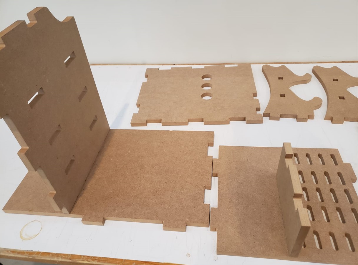
Result
This is the result of the shelf on my desk, I really liked the result, some pieces did not assemble perfectly, but with a little force it fit.