
10. Mechanical Design & Machine Design
Overview
The activity for this week was not easy...
We had to make a CNC machine from scratch! It was a
big challenge for the little time we had. We had a few stumbles
along the way, but I am pleased with the work of my team!
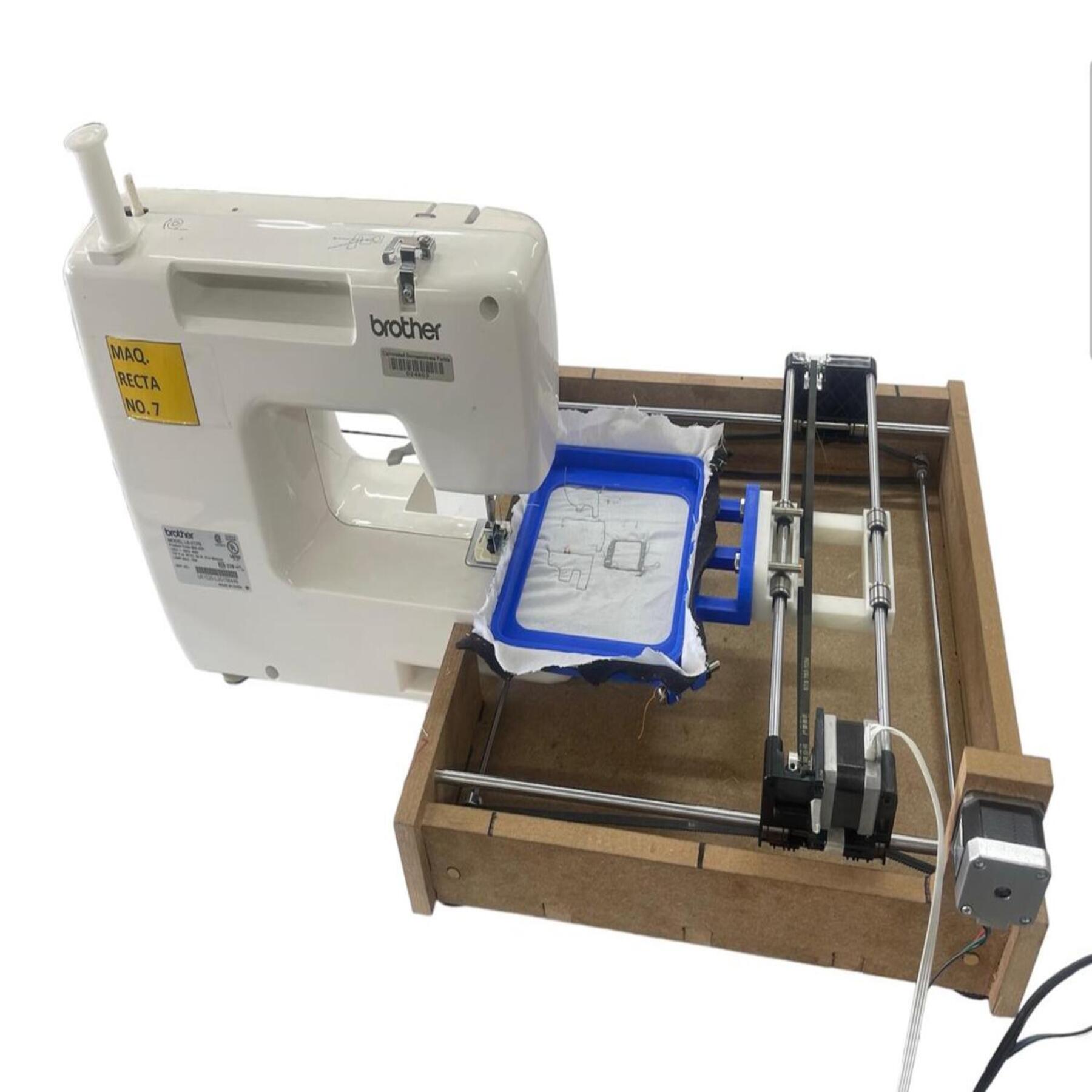
The CNC my team and I made was a sewing machine. Having a member
who is a textile teacher at my university, we chose a sewing machine.
The whole process of making the machine can be found in the following
link.
This is our cnc machine!:
What was my contribution to the development of this machine?
My contribution to develop this machine was to do all the part of running the machine using the Universal G-code sender (UGS) interface, and I was also in charge of testing the motors and developing the G-codes to test the machine.
Installing UGS
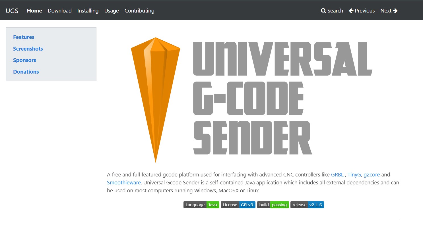
UGS, or Universal Gcode Sender, is a popular software interface used to send G-code commands to CNC machines, such as those controlled by GRBL. It is an open source application that allows users to communicate with their CNC, sending instructions to cut, engrave, drill or perform other operations. UGS is cross-platform compatible and stands out for its ease of use, allowing users to upload G-code files, view the tool path and adjust machine settings in real time.
Steps to install UGS:
- Visit their web page in our search engine, you can do it by clicking on the following .
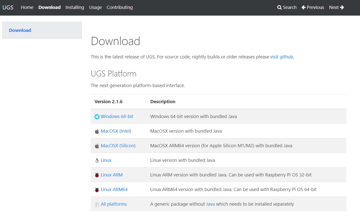
- To download the latest version of the software, go to Download. In this new tab we select our operating system. In our case, we use Windows and download version 2.1.6.
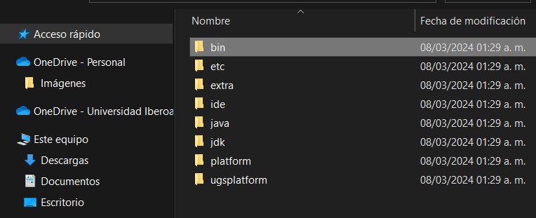
- At the end of the download, it will give us a compressed file, so it is necessary to decompress it. We use WinRaR to unzip the folder.
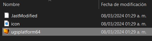
- We open the folder and go to "bin". Inside the bin folder we will find the program with the name "ugsplatform64". Before opening it, we send it to the desktop as a shortcut, to save us this step every time we use it.
- It takes a little while to load, but when opening the interface we can say that the installation has been a success.
Installation of GRBL on Arduino Uno for CNC control
Prerequisites:
- Hardware:
- Arduino Uno
- USB cable for connecting the Arduino to the computer
- Software:
- Arduino IDE (latest version)
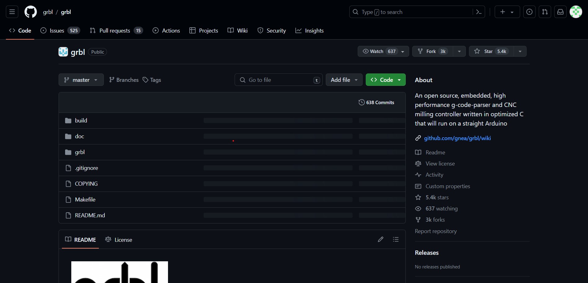
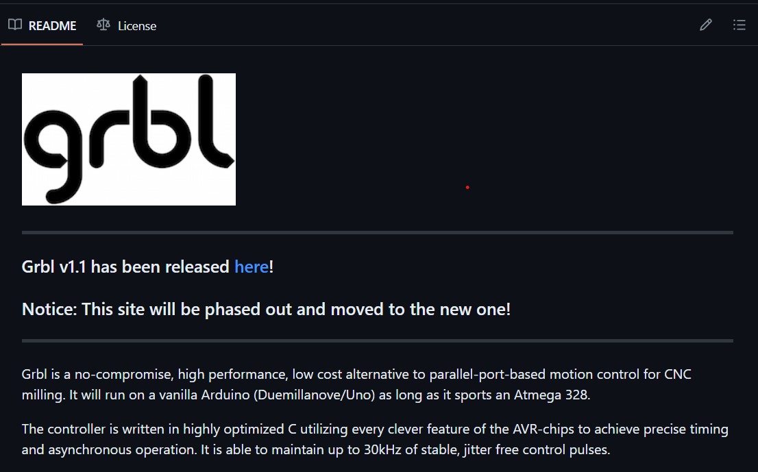
- GRBL firmware (latest version available on GitHub GRBL)
Installation
Step 1: Software preparation
- Download and install the Arduino IDE from the following link
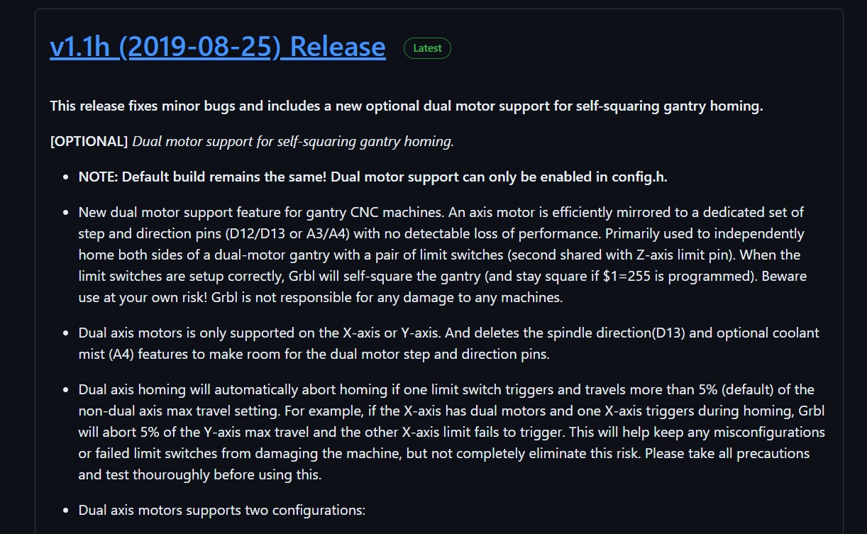
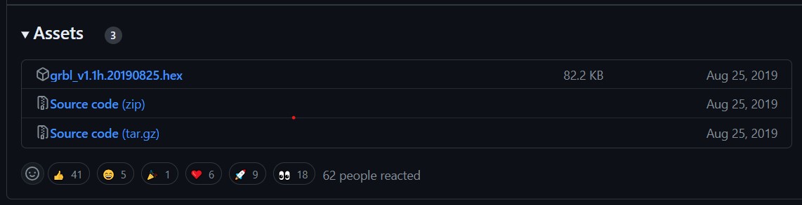
- Download the latest version of GRBL from GitHub GRBL Releases.
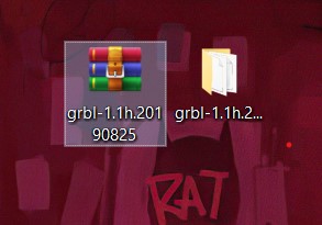
- Unzip the GRBL ZIP file.
Step 2: Loading GRBL on Arduino
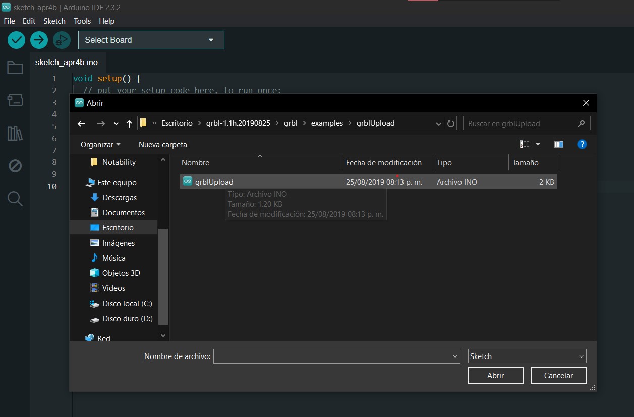
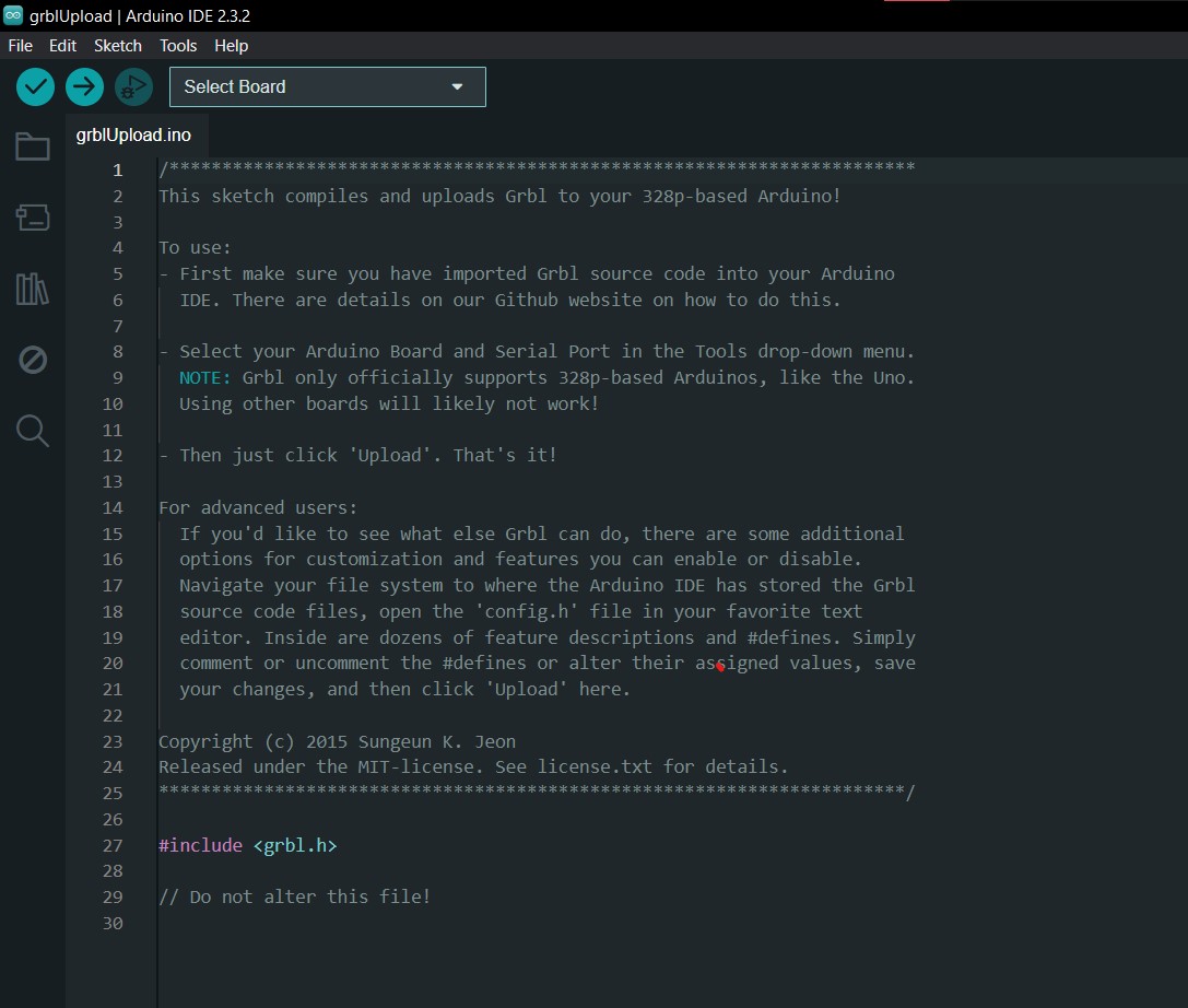
- Open Arduino IDE and go to "File" > "Open", navigate to the unzipped GRBL folder and open
grblUpload.ino. - When we open the file we will see the following.
- Connect the Arduino Uno to the computer using the USB cable.
- In Arduino IDE, select "Tools" > "Board" > "Arduino Uno".
- Select "Tools" > "Port" and choose the port to which the Arduino Uno is connected.
- Press the "Upload" button to upload GRBL to the Arduino Uno.
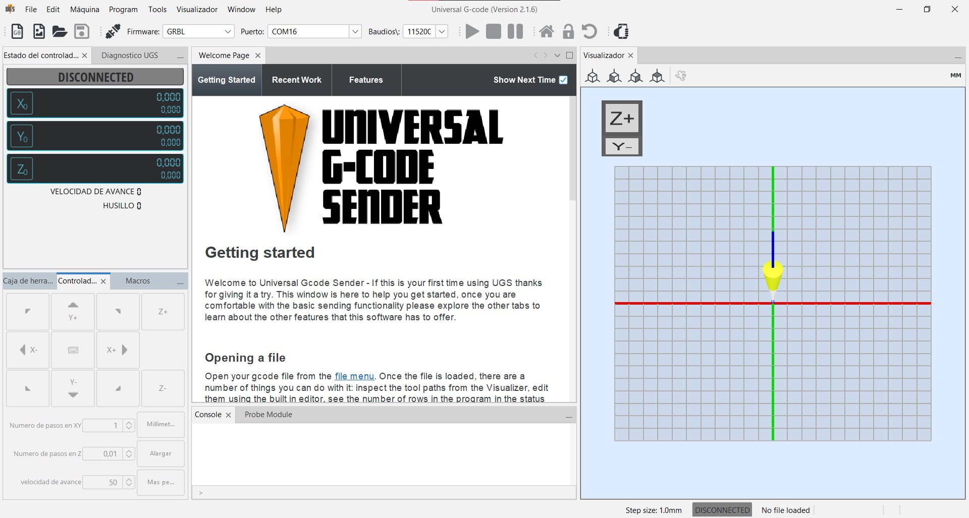
Universal Gcode Sender (UGS) Interface
Within UGS we have many tools for the operation of CNC machines.

Top Toolbar: This toolbar contains icons for quick operations such as opening G-code files, configuring the connection to the machine, and accessing different UGS tools and settings. Here you select the firmware (usually GRBL), choose the correct port to which the Arduino is connected, and set the baud rate for communication.
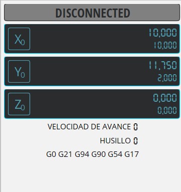
Status Panel: Displays vital information about the status of the connection between UGS and the CNC. It indicates if the machine is connected and ready to receive commands or if there is a problem with the connection.
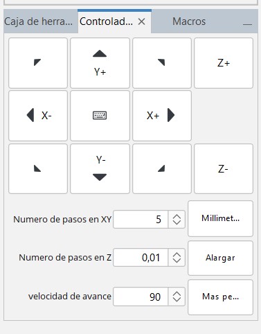
- Manual Motion Controls: A set of buttons that allow manual control of the CNC machine axes. You can move the X, Y and Z axes in defined increments, which is useful for initial positioning or to verify motion.
- Step and Speed Setup: In this area you can define the amount of motion for each command sent and adjust the machine's feed rate. This is crucial for precise work and to adapt the machine to the specific needs of each operation.
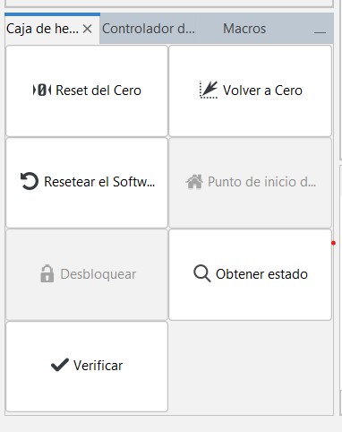
Control Panel: Provides shortcuts to frequently used functions such as "Reset from Zero" to set the working origin and "Back to Zero" to return to the defined origin point. It also allows unlocking the controller and checking the current status of the machine.
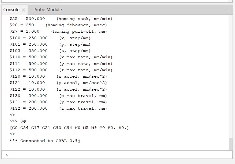
Console: A text window that shows in real time the communication between UGS and the CNC machine. Commands sent, machine responses and any error messages are displayed here. It is useful for diagnosing problems and confirming that G-code commands are being sent correctly.
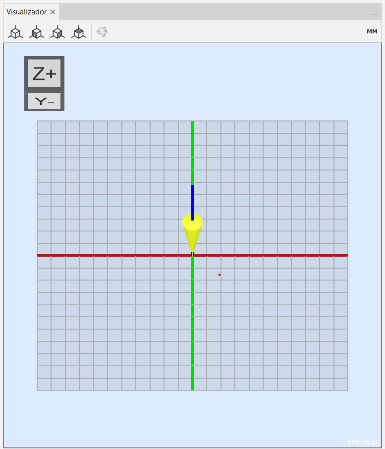
Visualizer: una función clave que permite a los usuarios ver una representación gráfica del trayecto que seguirá la herramienta de corte en la máquina CNC. Este visualizador muestra el código G en forma de líneas y movimientos sobre un plano que simula la superficie de trabajo del CNC.
Testing motors at UGS
After we had all the software part ready, we checked that the hardware part was also ready. For this part we used the following:
- Arduino Uno: This is the central microcontroller, which runs the CNC firmware and coordinates the control signals for the movements of the motors and the sewing machine needle.
- CNC Shield: An expansion board that sits on top of the Arduino Uno, facilitating the connection and management of the stepper motor drivers and other peripheral components.
- Motor Drivers: Drivers for the stepper motors. The colors of the drivers may indicate different versions or features, such as the maximum current supported.
- Capacitors on Driver Pins: These are elements that can be added to modify motor behavior, such as smoothing motion or reducing noise. They can be decoupling capacitors or similar, which help filter electrical noise and improve performance.
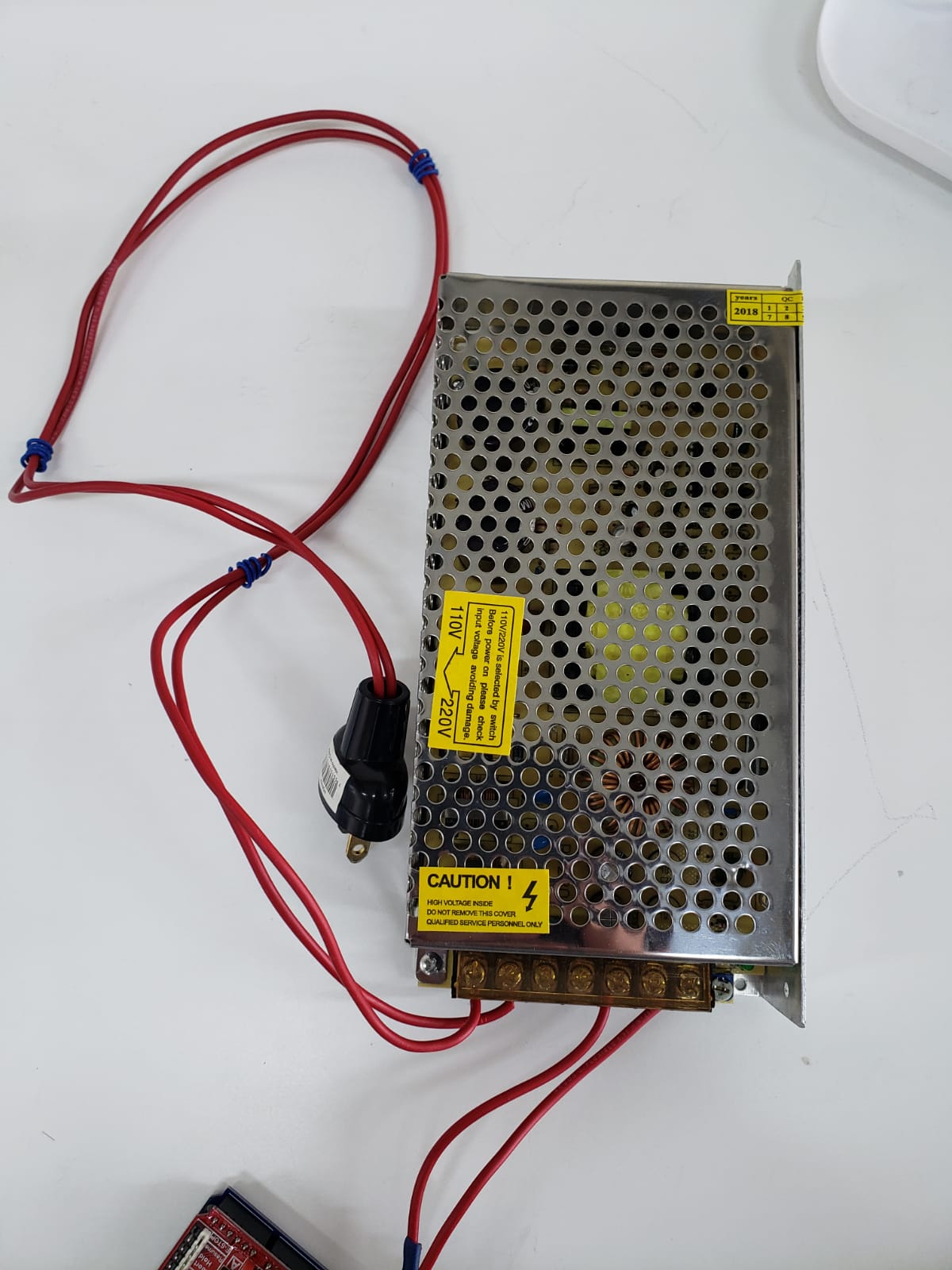
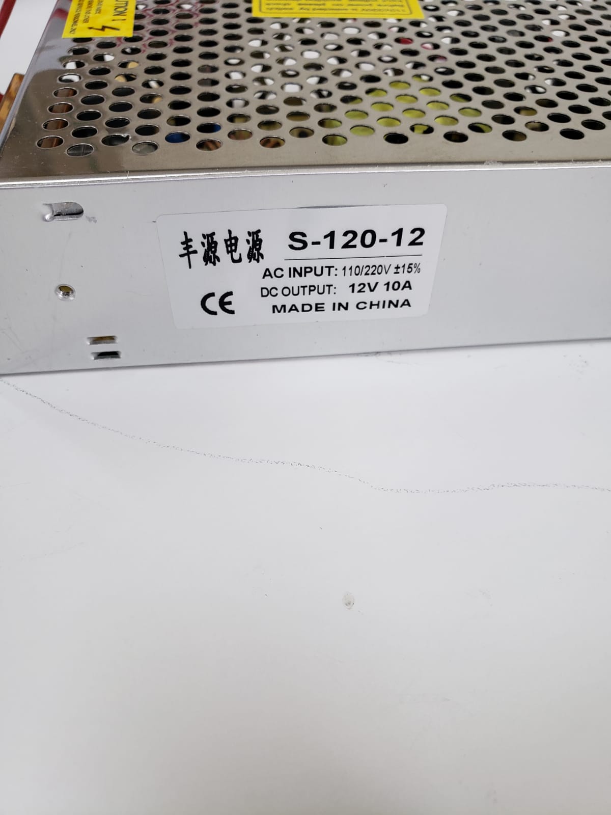
- 12V Power Supply: Provides the necessary power for the motors and the Arduino board.
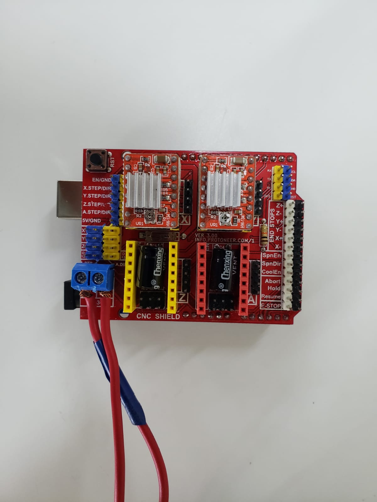
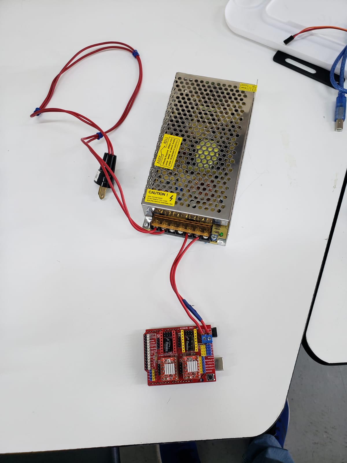
To connect the arduino to the power supply you have to connect the power wires to the screw terminal blocks. After this step we connect the drivers to the shield. The drivers we used are red, but at first we used green drivers, but they stopped working :(.

The next thing was to connect the motors to the arduino shield and connect the arduino to my laptop.
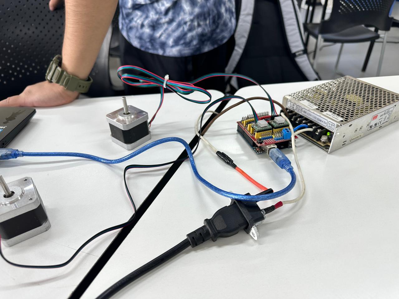
To connect the arduino to UGS we use the tool next to Firmware in the Top toolbar. However, before doing this, we choose the port where we have connected the arduino.

To test the motors in UGS we use this tool, which allows us to move them manually. We can move any axis. We can also adjust the steps of the motors per axis and their speed.
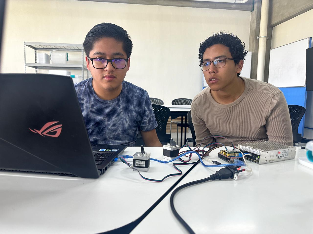
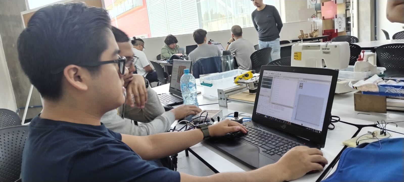
For this step I was helped by my teammate Augusto. Here are a couple of videos and some pictures testing the motors.
Here are Augusto and I testing how UGS works:
In this other image we are testing a G-code of a square in UGS:
Here is the video of the G-code square, we did this to know the speed at which the motors were working.
Testing of the motors with the sewing machine.
To do this test we set up the bed motors with the x and y axes. For the z-axis, we use the
machine needle, which can be controlled by the sewing machine foot pedal. So we had to open
the pedal and created a small mechanism with a motor and a 3D printed part. This is important
because we had to adjust our G-code.
We thought of using Inkscape software to generate G-code. We found an additional tool to set up
G-code for sewing machines called Ink Stitch. However, we did not use it because we faced different
problems, so to make it faster, we generated our own codes.
To make it easier to create our own G-codes, we made drawings to help us visually.
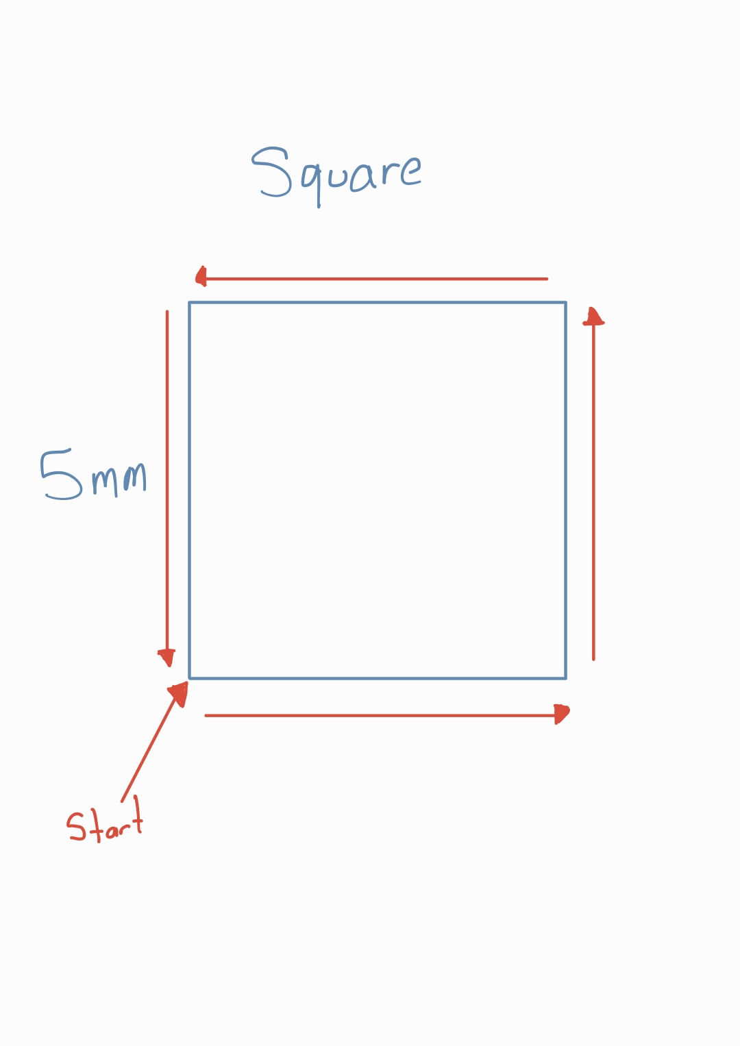
The first one we made was for a square:
G21 ; Set units to millimeters
G90 ; Use absolute positioning
G17 ; Select XY plane

; Lift the head to 5mm above the material to avoid scratches
G0 X0 Y0 ; Move to the starting position (optional if you're already at 0,0)

G0 Z-0.23 F200
G1 Z0 F80 ; Lower the head to the material level at a feed rate of 80
G1 X-5 Y0 F80
G1 X-5 Y-5 F150
G1 X0
As you can see, the code is very simple, before running the x and y axes of the bed, we turn on the sewing machine with the z axis. At the end of the figure we turn off the machine.
The other figure we made was a letter F:
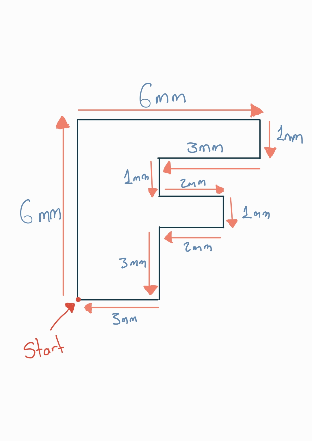
Here the G-code:
G21 ; Set units to millimeters
G90 ; Use absolute positioning

; Move to the starting position
G0 X0 Y0

G0 Z-0.23 F200

; 1. Move up to start the vertical column of the "F"
G1 X0 Y6 F120

; 2. Move right to form the top stroke of the "F"
G1 X6 Y6 F120

; 3. Move down to start the first notch
G1 X6 Y5 F120

; 4. Move left for the top notch
G1 X3 Y5 F120

; 5. Move down to the initial position of the middle line
G1 X3 Y3 F120

; 6. Move right for the middle line
G1 X5 Y3 F120

; 7. Move down for the second notch
G1 X5 Y2 F120

; 8. Move left to complete the middle notch
G1 X3 Y2 F120

; 9. Move up to connect with the vertical column
G1 X3 Y0 F120

; 10. Move left to return to the starting position and close the letter "F"
G1 X0 Y0 F120

G0 Z0 F200
I don't have space to post the video of the machine working with these two codes, but you can see them on the group page at the following link.
But I can put the result we got:
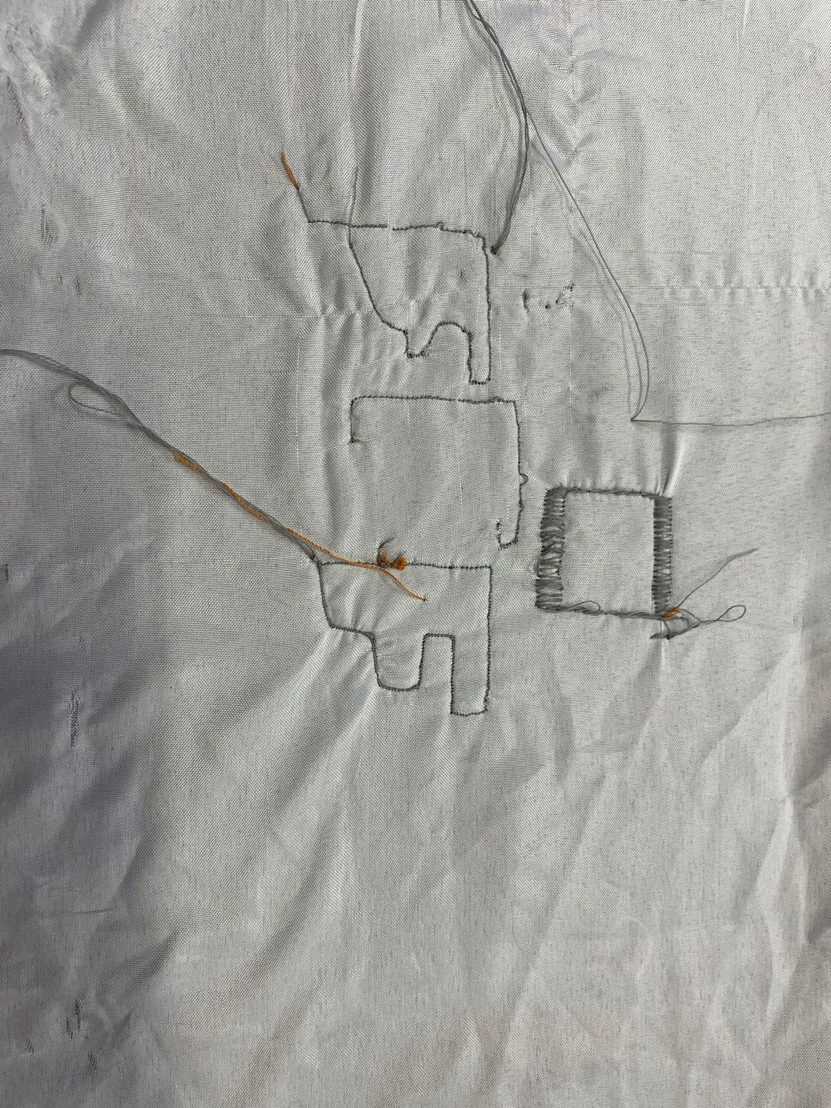
We use two different stitches, a zigzag stitch and a normal straight stitch.