13. Networkings and comunications
Overview
This week's group assignment is to design, build and connect wired or wireless nodes with network or bus addresses and a local interface. You can consult the group page at the following link.
Communication protocols
In the world of electronics and robotics, effective communication between different devices and components is crucial. UART, I2C, and SPI are three of the most common communication interfaces used for this purpose. Each protocol has unique features that make them suitable for different applications, and understanding their differences is essential to choose the best option for a specific project.
UART (Universal Asynchronous Receiver/Transmitter)

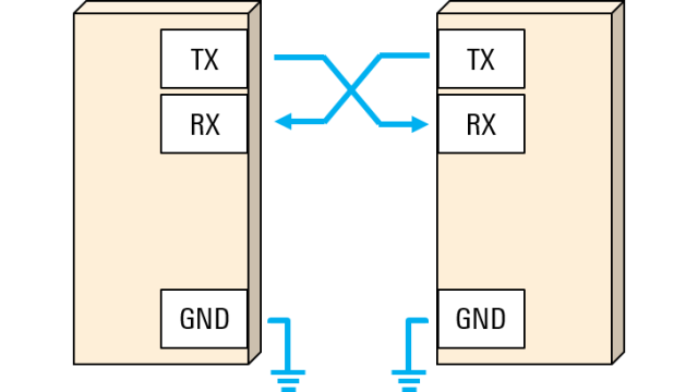
How it works: UART is a serial communication protocol that allows the transmission of data between devices asynchronously. It uses two main lines: TX (transmission) and RX (reception), enabling full-duplex communication between two devices.
- Advantages:
- Disadvantages:
Simplicity
Easy to implement and understand, with minimal hardware requirements.
Universality
Widely supported and used in the industry, available in most microcontrollers.
Limited Speed
Not ideal for high-speed data transmission compared to other protocols like SPI.
No Bus Management
Does not support multiple devices on the same bus without additional hardware.
I2C (Inter-Integrated Circuit)

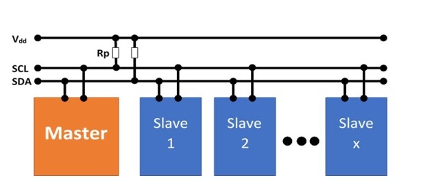
How it works: I2C is a serial communication protocol that uses two lines: SCL (clock) and SDA (data). It allows multi-master and multi-slave communication, where multiple devices can connect and communicate with each other using the same set of lines.
- Advantages:
- Disadvantages:
Multi-master and Multi-slave Capability
Allows multiple devices to connect and communicate using just two wires.
Integrated Bus Management
Includes features such as ACK/NACK generation, which facilitates the management of communications.
Complexity of Implementation
More complex to configure correctly than UART.
Moderate Speed
Generally slower than SPI.
SPI (Serial Peripheral Interface)

How it works: SPI is a serial communication protocol based on a master/slave concept that uses a clock wire (SCK), a data output wire (MOSI), a data input wire (MISO), and a slave select wire (SS) for each slave on the bus.
- Advantages:
- Disadvantages:
High Speed
Capable of higher transmission speeds compared to UART and I2C.
Simple Control
The master/slave design simplifies the control of multiple devices.
Requires More Pins
As more slaves are added, more slave select lines are needed, using more pins of the microcontroller.
No Native Support for Multi-master
Designed primarily for single-master configurations.
UART communication
The UART (Universal Asynchronous Receiver/Transmitter) is a serial protocol that allows asynchronous data exchange between devices. It is known for its simplicity and efficiency, utilizing just two lines for communication: TX (transmit) and RX (receive). Unlike other protocols like I2C and SPI, UART does not require a clock line to synchronize data.
Functionality of UART Communication
- TX (Transmit): The pin through which a device sends data.
- RX (Receive): The pin through which the device receives data.
- The communication is full-duplex, meaning devices can send and receive data simultaneously.
Serial Monitor in UART Communication
The Serial Monitor is an essential tool used in conjunction with UART communication, particularly during the development and debugging of software on microcontrollers. It operates by connecting the microcontroller to a computer via a USB port that simulates a serial connection.
Functions of the Serial Monitor
- Viewing Data: Allows you to see data sent by the microcontroller in real time. Any message sent from the device using commands like
Serial.print()orSerial.println()will appear on the Serial Monitor. - Sending Data: You can send data from the computer to the microcontroller. This is useful for sending commands to the device or adjusting parameters without needing to reprogram the chip.
- Setting Baud Rate: The communication speed (baud rate) must be configured both on the microcontroller and the Serial Monitor to ensure that data is transmitted correctly without errors or corruption.
- Ground Connection: The GND (Ground) must also be connected between the devices to ensure a common reference for the signals.
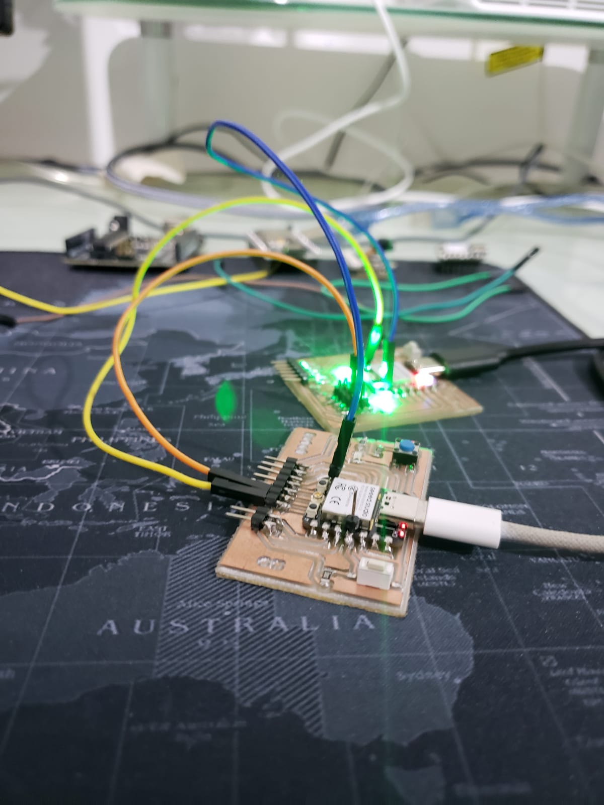
The connection of this communication is very simple. Only two devices can be connected. For this communication I used a Xiao ESP32-C3 and a Xiao RP-2040. The transmitter for this communication was the Xiao ESP32-C3 and the receiver was the Xiao RP-2040. For this I connected the TX pin of the transmitter to the RX pin of the receiver and the ground wire.
What I did to test this type of communication was to turn on an LED of the other device with a button. Here is the transmitter code:
    #include <Arduino.h>

    const int buttonPin = D0;
    const int ledPin = D1;

    void setup() {
        pinMode(buttonPin, INPUT); // Set up the button without internal pull-up
        pinMode(ledPin, OUTPUT); // Optional: LED pin on the transmitter for visual feedback
        Serial.begin(9600); // Initialize Serial for debugging via USB
        Serial1.begin(9600, SERIAL_8N1, D7, D6); // Initialize UART on pins 20 and 21
        Serial.println("Transmitter XIAO ESP32-C3 Ready");
    }

    void loop() {
        static bool lastButtonState = LOW; // Previous button state, assuming pull-down
        bool currentButtonState = digitalRead(buttonPin); // Read the current button state

        // Check if the button was pressed (change from LOW to HIGH)
        if (lastButtonState == LOW && currentButtonState == HIGH) {
            Serial1.println("LED_ON\n"); // Send the command to turn on the LED on the receiver
            Serial.println("Command Sent: LED_ON"); // Debug message
            digitalWrite(ledPin, HIGH); // Optional: Turn on the LED on the transmitter
            delay(1000); // Optional: Keep the LED on for one second
            digitalWrite(ledPin, LOW); // Optional: Turn off the LED on the transmitter
        }
        lastButtonState = currentButtonState; // Update the previous button state for the next read

        delay(50); // Small delay for debouncing
    }
The code works as follows:
-
Inclusion of the Arduino.h library:
Arduino.h library is included, providing standard functions and definitions for Arduino programming.
-
Pin definition:
The pins
buttonPinandledPinare defined to be used for connecting the button and the LED, respectively. -
Setup function:
The
setup()function is defined, which runs once at the beginning of the program.The
buttonPinis configured as input and theledPinas output.Serial communications are initiated for USB debugging and UART communication (asynchronous communication) using pins D7 and D6.
-
Loop function:
The
loop()function is defined, which runs continuously aftersetup()has finished.A variable
lastButtonStateis declared to store the previous state of the button.The current state of the button is read using the
digitalRead(buttonPin)function.The current state of the button is compared with the previous state to detect changes (from low to high), indicating that the button has been pressed.
If a change in the button state is detected, a message is sent via serial communication (
Serial1.println()) to activate an LED on the receiver.The previous button state is updated for the next iteration of the loop.
A small delay (
delay(50)) is added to avoid button bounce.
Here is the receiver code:
    // Include Arduino.h library:
    #include <Arduino.h>

    // Define LED pin:
    const int ledPin = 26;

    // Setup function:
    void setup() {
        pinMode(ledPin, OUTPUT); // Configure LED pin as output
        Serial1.begin(9600); // Start UART communication at 9600 baud rate
        Serial.begin(9600); // Start Serial for USB debugging
        Serial.println("Receiver RP2040 Ready");
    }

    // Loop function:
    void loop() {
        if (Serial1.available()) { // Check if data is available to read
            String message = Serial1.readStringUntil('\n'); // Read incoming message
            if (message == "LED_ON") {
                digitalWrite(ledPin, HIGH); // Turn on the LED
                Serial.println("LED on RP2040 is ON"); // Debug message
                delay(1000); // Keep the LED on for 1 second
                digitalWrite(ledPin, LOW); // Turn off the LED
            }
        }
    }
The code works as follows:
-
Inclusion of the Arduino.h library:
Arduino.h library is included, providing standard functions and definitions for Arduino programming.
-
Pin definition:
The pin
ledPinis defined as pin 26, which will be used to connect the LED. -
Setup function:
The
setup()function is defined, which runs once at the beginning of the program.The
ledPinis configured as an output pin.Serial communication is initiated for UART communication at 9600 baud rate for both
SerialandSerial1.A message indicating the readiness of the receiver (RP2040) is printed through
Serial. -
Loop function:
The
loop()function is defined, which runs continuously aftersetup()has finished.It checks if there is data available to read from
Serial1.If data is available, it reads the incoming message until a newline character is encountered.
If the message is "LED_ON", it turns on the LED connected to
ledPin, prints a debug message indicating the LED status, keeps the LED on for 1 second, and then turns it off.
The following image shows the connection of the two devices I used:

Result:
I2C communication
In an I2C communication, there are two main roles: the master and the slave. The master is responsible for initiating and controlling the communication, while the slaves respond to the master's requests. A master can communicate with one or multiple slaves using their unique addresses on the I2C bus.
Key Components
- Data Line (SDA): This line carries the data between the master and the slaves.
- Clock Line (SCL): This line is used by the master to synchronize data transmission.
Communication Process
- Start Condition: The master initiates the communication by generating a start condition, where SDA goes low while SCL is high.
- Slave Address: The master sends the address of the slave it wants to communicate with. This address is a byte that includes the device address and a read/write bit.
- Acknowledgment (ACK): The slave acknowledges the address sent by the master by sending an acknowledgment bit (ACK) back to the master.
- Data Transfer: Depending on whether it is a read or write operation, the master or the slave will send or receive data. Each byte of data sent must be acknowledged with an ACK.
- Stop Condition: Once the data transmission is complete, the master ends the communication by generating a stop condition, where SDA goes high while SCL is high.
For this communication I connected an Arduino Uno as master, a Xiao ESP32-C3 and a Xiao RP-2040 as slaves. The programming was simple, I configured the slaves so that they could communicate using buttons and LEDs. When I press a button on one slave a led on the other slave lights up and the same happens with the other slave. Below is the code for the master:
    #include <Wire.h>

    #define SLAVE1_ADDRESS 0x08 // I2C address of the first slave
    #define SLAVE2_ADDRESS 0x09 // I2C address of the second slave

    void setup() {
    Wire.begin(); // Start I2C communication
    Serial.begin(9600);
    }

    void loop() {
    // Request button state from the first slave
    Wire.requestFrom(SLAVE1_ADDRESS, 1);
    if (Wire.available()) {
        int buttonState1 = Wire.read();
        if (buttonState1 == HIGH) {
        // Send command to the second slave to turn on LED
        Wire.beginTransmission(SLAVE2_ADDRESS);
        Wire.write(1); // Turn on LED
        Wire.endTransmission();
        } else {
        // Send command to the second slave to turn off LED
        Wire.beginTransmission(SLAVE2_ADDRESS);
        Wire.write(0); // Turn off LED
        Wire.endTransmission();
        }
    }

    // Request button state from the second slave
    Wire.requestFrom(SLAVE2_ADDRESS, 1);
    if (Wire.available()) {
        int buttonState2 = Wire.read();
        if (buttonState2 == HIGH) {
        // Send command to the first slave to turn on LED
        Wire.beginTransmission(SLAVE1_ADDRESS);
        Wire.write(1); // Turn on LED
        Wire.endTransmission();
        } else {
        // Send command to the first slave to turn off LED
        Wire.beginTransmission(SLAVE1_ADDRESS);
        Wire.write(0); // Turn off LED
        Wire.endTransmission();
        }
    }

    delay(100); // Small delay to avoid saturating the I2C bus
    }
The code works as follows:
-
Inclusion of the Wire.h Library:
The
Wire.hlibrary is included for I2C communication. -
Define I2C Slave Addresses:
SLAVE1_ADDRESSis0x08andSLAVE2_ADDRESSis0x09. -
Setup Function:
Wire.begin()initializes I2C communication andSerial.begin(9600)starts serial communication for debugging. -
Loop Function:
The
loop()function runs continuously aftersetup(). -
Request Button State from First Slave:
Wire.requestFrom(SLAVE1_ADDRESS, 1)requests data from the first slave. IfbuttonState1isHIGH, it sends a command to turn on the LED on the second slave, otherwise it sends a command to turn it off. -
Request Button State from Second Slave:
Wire.requestFrom(SLAVE2_ADDRESS, 1)requests data from the second slave. IfbuttonState2isHIGH, it sends a command to turn on the LED on the first slave, otherwise it sends a command to turn it off. -
Delay:
delay(100)prevents the I2C bus from being overwhelmed.
The following code is for the first slave:
    #include <Wire.h>

    #define BUTTON_PIN D0
    #define LED_PIN D1

    void setup() {
        pinMode(BUTTON_PIN, INPUT_PULLUP);
        pinMode(LED_PIN, OUTPUT);
        Wire.begin(0x08); // I2C address of the first slave
        Wire.onRequest(onRequest);
        Wire.onReceive(onReceive);
    }

    void loop() {
        // Nothing to do in the main loop, I2C functions handle the communication
    }

    void onRequest() {
        int buttonState = digitalRead(BUTTON_PIN);
        Wire.write(buttonState);
    }

    void onReceive(int numBytes) {
        while (Wire.available()) {
            int command = Wire.read();
            if (command == 1) {
                digitalWrite(LED_PIN, HIGH); // Turn on LED
            } else {
                digitalWrite(LED_PIN, LOW); // Turn off LED
            }
        }
    }
The code works as follows:
-
Inclusion of the Wire.h Library:
The Wire.h library is included, providing functionalities to use the I2C communication protocol.
-
Define Pins:
BUTTON_PIN is defined as D0, representing the button pin. LED_PIN is defined as D1, representing the LED pin.
-
Setup Function:
The
setup()function initializes pin modes and I2C communication. The button pin is set as an input with an internal pull-up resistor, and the LED pin is set as an output. I2C is initialized with the address 0x08, and request and receive handlers are defined. -
Loop Function:
The
loop()function is empty because the I2C handlers manage the communication. -
onRequest Function:
The
onRequest()function reads the button state and sends it via I2C when requested. -
onReceive Function:
The
onReceive(int numBytes)function receives a command via I2C to either turn on or off the LED based on the received value.
The following code is for the second slave:
    #include <Wire.h>

    #define BUTTON_PIN D1
    #define LED_PIN 26

    void setup() {
        pinMode(BUTTON_PIN, INPUT_PULLUP);
        pinMode(LED_PIN, OUTPUT);
        Wire.begin(0x09); // I2C address of the second slave
        Wire.onRequest(onRequest);
        Wire.onReceive(onReceive);
    }

    void loop() {
        // Nothing to do in the main loop, the I2C functions handle the communication
    }

    void onRequest() {
        int buttonState = digitalRead(BUTTON_PIN);
        Wire.write(buttonState);
    }

    void onReceive(int numBytes) {
        while (Wire.available()) {
        int command = Wire.read();
        if (command == 1) {
            digitalWrite(LED_PIN, HIGH); // Turn on LED
        } else {
            digitalWrite(LED_PIN, LOW); // Turn off LED
        }
        }
    }
The code works as follows:
-
Inclusion of the Wire.h Library:
The Wire.h library is included, providing functionalities to use the I2C communication protocol.
-
Define Pins:
BUTTON_PIN is defined as D0, representing the button pin. LED_PIN is defined as D1, representing the LED pin.
-
Setup Function:
The
setup()function initializes pin modes and I2C communication. The button pin is set as an input with an internal pull-up resistor, and the LED pin is set as an output. I2C is initialized with the address 0x08, and request and receive handlers are defined. -
Loop Function:
The
loop()function is empty because the I2C handlers manage the communication. -
onRequest Function:
The
onRequest()function reads the button state and sends it via I2C when requested. -
onReceive Function:
The
onReceive(int numBytes)function receives a command via I2C to either turn on or off the LED based on the received value.