
3. Computer Controlled Cutting
Overview
This week's group assignment consisted of characterization on focus, power, speed, rate, kerf, joint clearance and laser cutter types. The group assignment is at the following link.
What did I learn from the group assignment?
From this assignment I learned to not only use the laser cutting machines that the university has. I learned some things that allow the machine to deliver better results. For example, the use of the kerf for the individual activity was very important because it allowed me to pressure assemble the parts to fit well. As for speed and power, I learned how to adjust these parameters so that the laser cutter would do a good job. By this I mean that it would cut all the parts without burning the material.
Laser Machine
The laser machine I used to cut my construction kit is the CFL-CMA1080K machine.
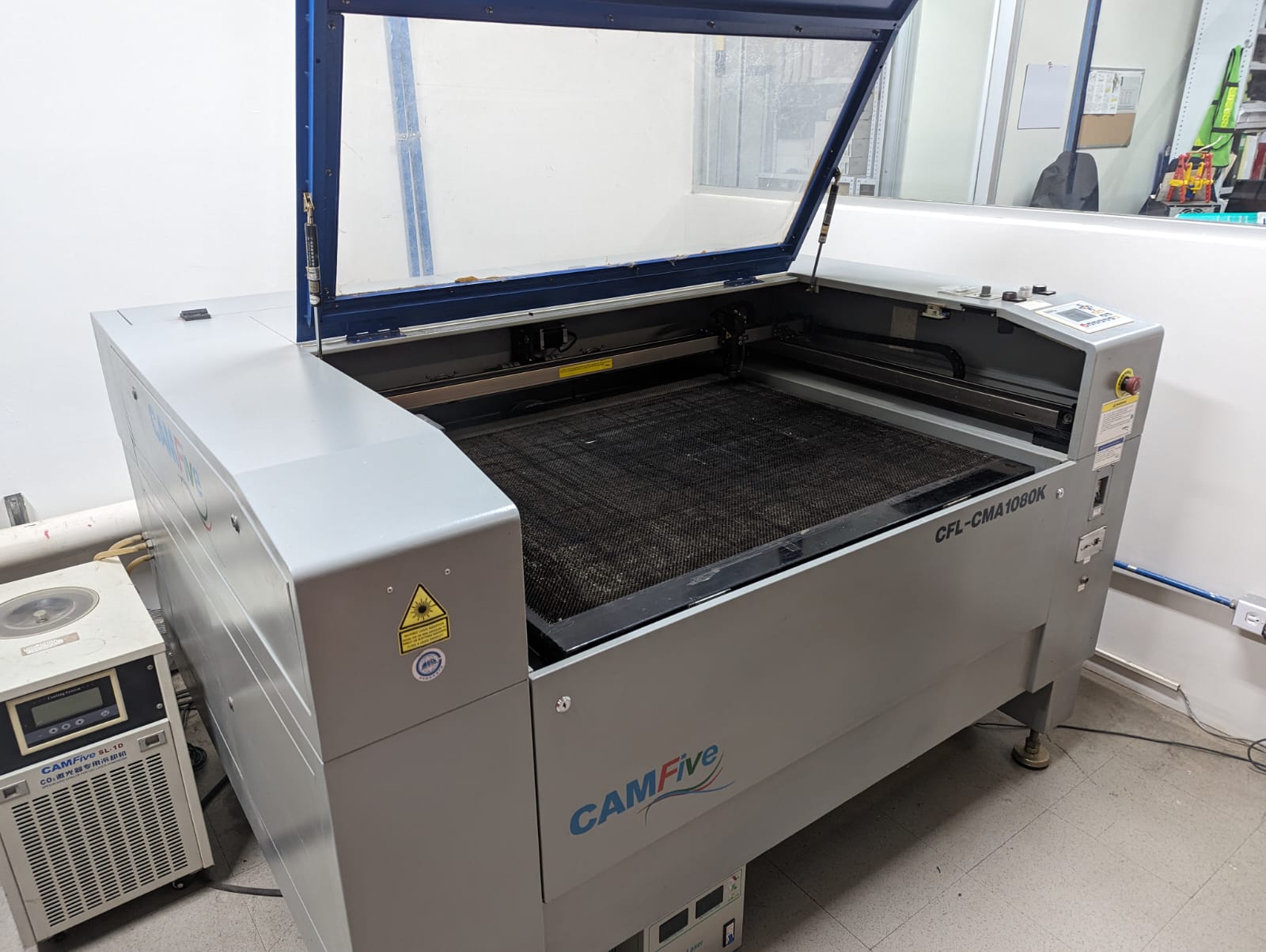
This machine has the following features:
Work area
1.00 x 0.80 meters
Work table
Honeycomb or rod
Accessory
Double Tube
Cutting speed
0–36,000 (min/mm)
Engraving speed
0-64000 (min/mm)
Power
100 Watts
Cutting thickness
0–25 mm
Resolution
Up to 4000 DPI (600–2000 DPI typically)
Motion accuracy
0.01 mm
The steps I followed to use the machine can be found in the following link.
Type of material for laser machine:
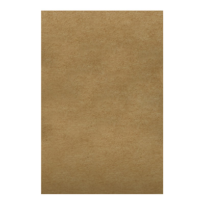
The material I used to assemble the kit is MDF.
MDF (Medium Density Fiberboard) is a versatile and cost-effective type of pressed wood fiberboard used in furniture and woodworking projects due to its easy handling and uniform finish.
Individual assignment: construction kit
This assignment consisted of making a construction kit using CAD software. The software I used was Fusion 360. I used this software for two reasons: the first is because in week two's assignment I learned how to use that software and the second is that SolidWorks was taking a long time to load on my computer.
Parametric design
Parametric design in allows for creating 3D models with adjustable parameters, facilitating iteration and design optimization.
My construction kit is made with parametric design, which allows me to make modifications to the figures I drew.
To calculate the "kerf" or the amount of material burned by a laser cutter, several cuts can be made in a material and the space created by these cuts can be measured. By dividing the total width of the gap by the number of cuts, the kerf width is obtained. For example, in the group activity, by making 10 cuts in 3 mm MDF with a speed of 40 mm/s and 50% power, and measuring a total space of .123 mm, the resulting kerf is 0.123 mm. This value was used to adjust the dimensions in the fabrication of my construction kit, ensuring accurate assembly.
Development of figures in Fusion 360
All the tools I used in Fusion 360 are the ones I learned in week two. You can check out week two here.
Figure 1. Main piece: A rectangle with tabs and some holes to insert other pieces.
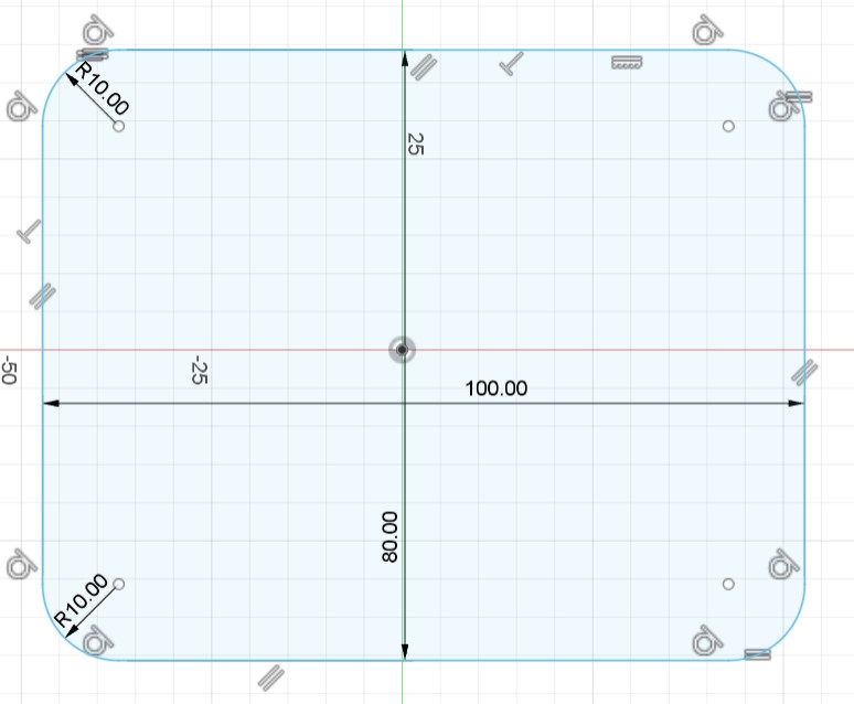
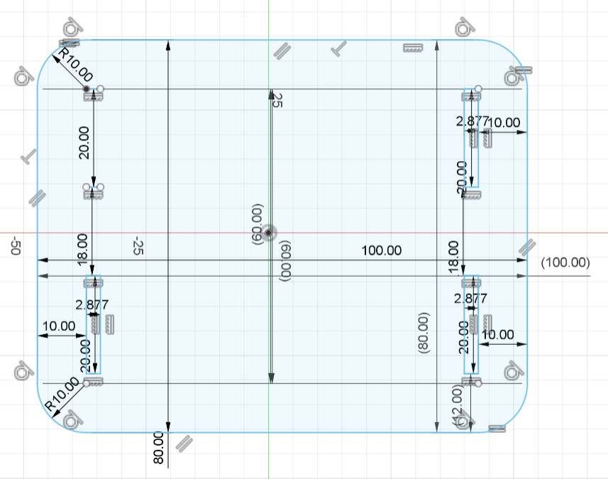
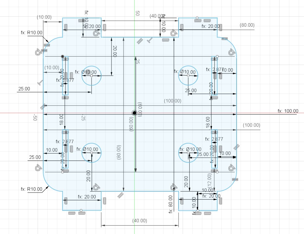
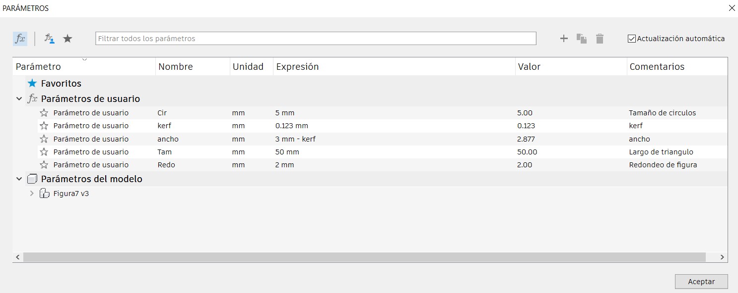
Figure 1 parameters:
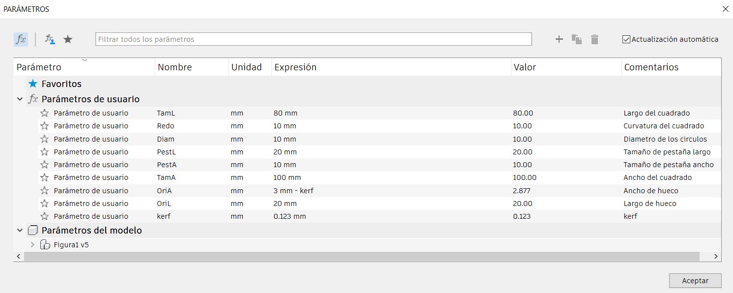
Figure 2. Main piece wall: A rectangle with holes to insert other pieces.
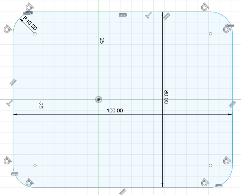
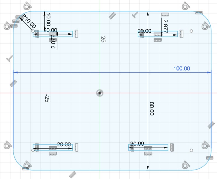
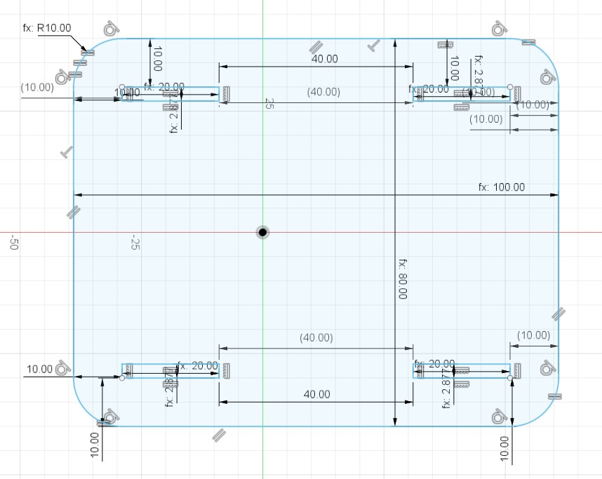
Figure 2 parameters:
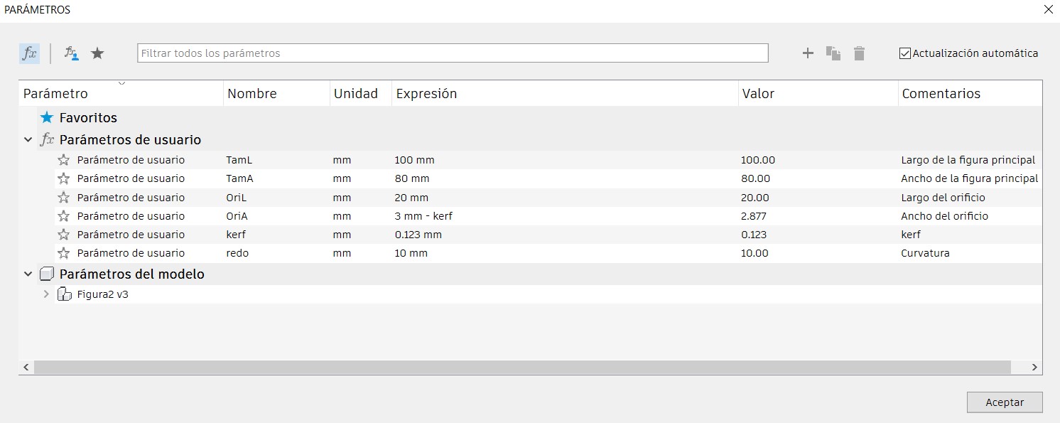
Figure 3. Main piece ceiling: A rectangle with tabs and a design in the center.
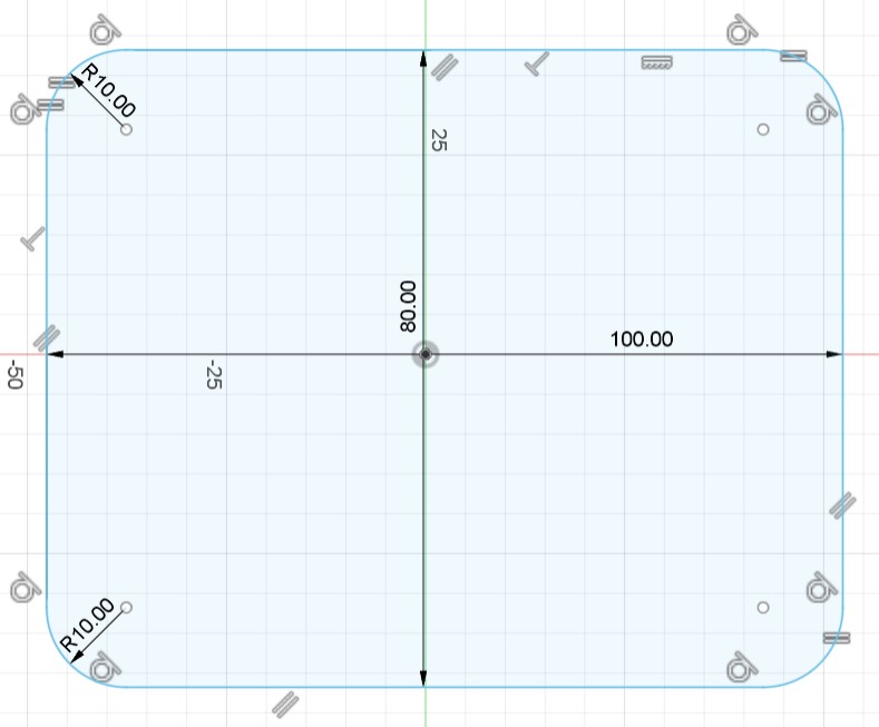
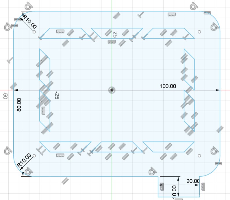
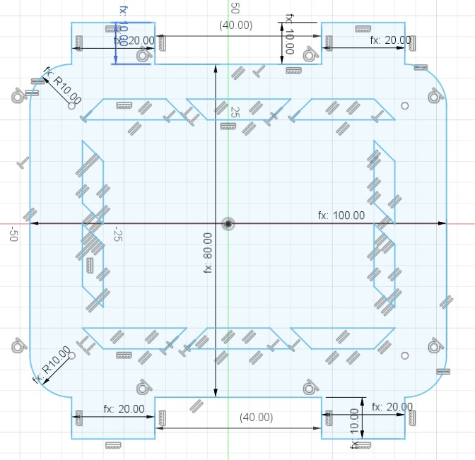
Figure 3 parameters:
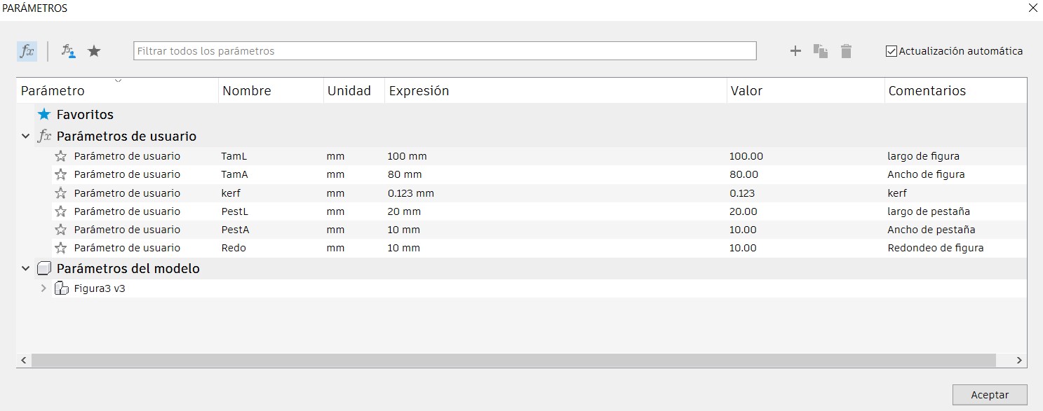
Figure 4. Wheel.
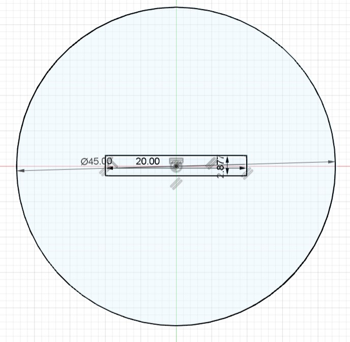
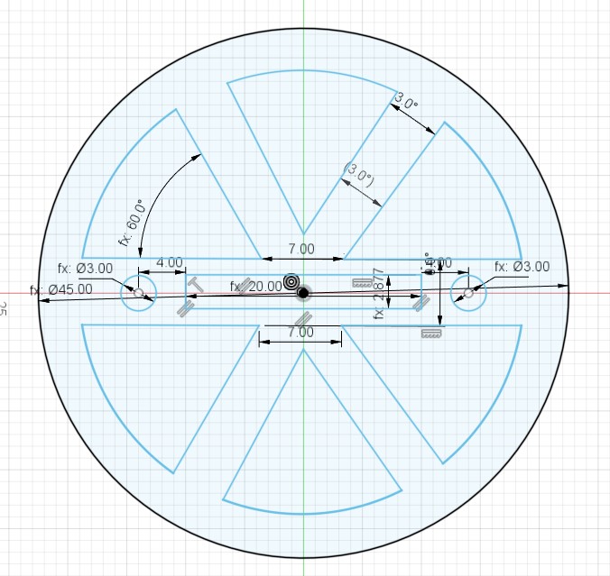
Figure 4 parameters:
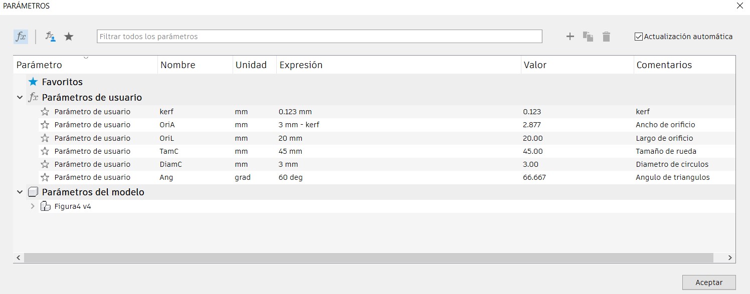
Figure 5. Other wall type.
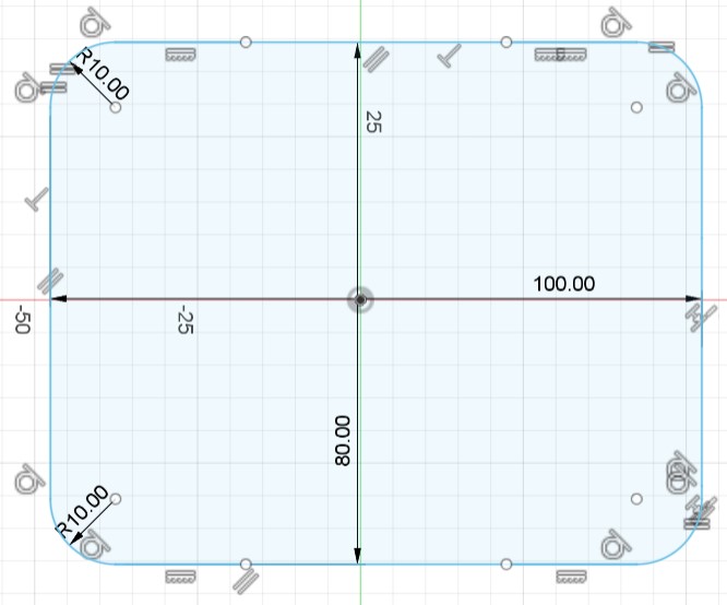
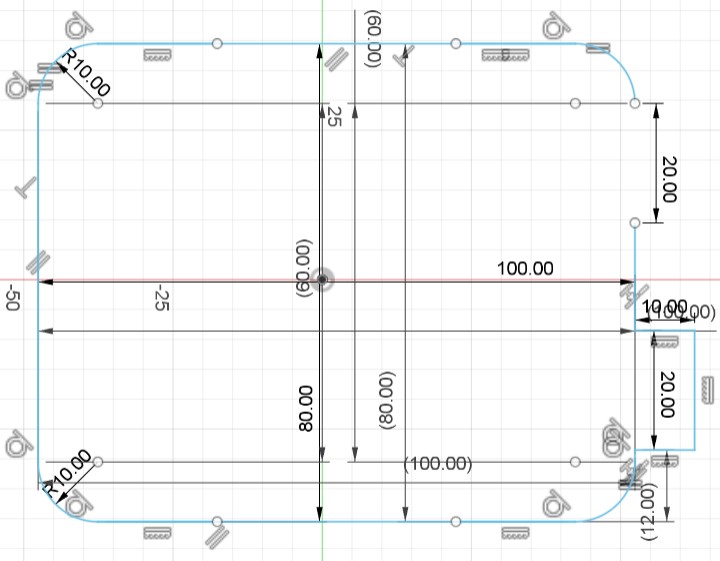
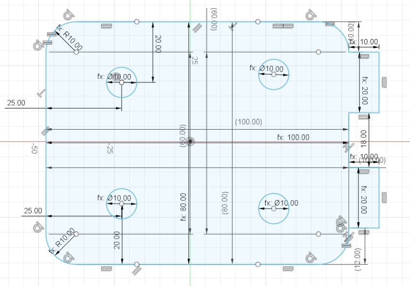
Figure 5 parameters:
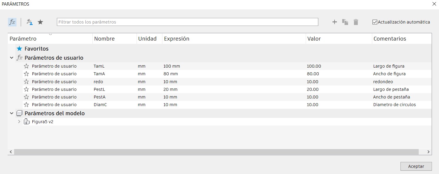
Figure 6. Elbow.
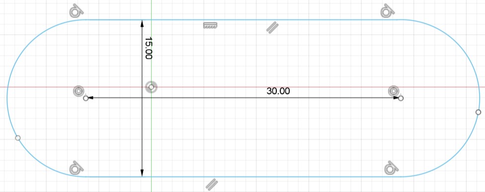
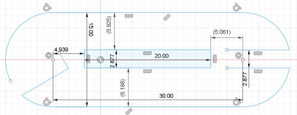
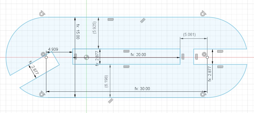
Figure 6 parameters:
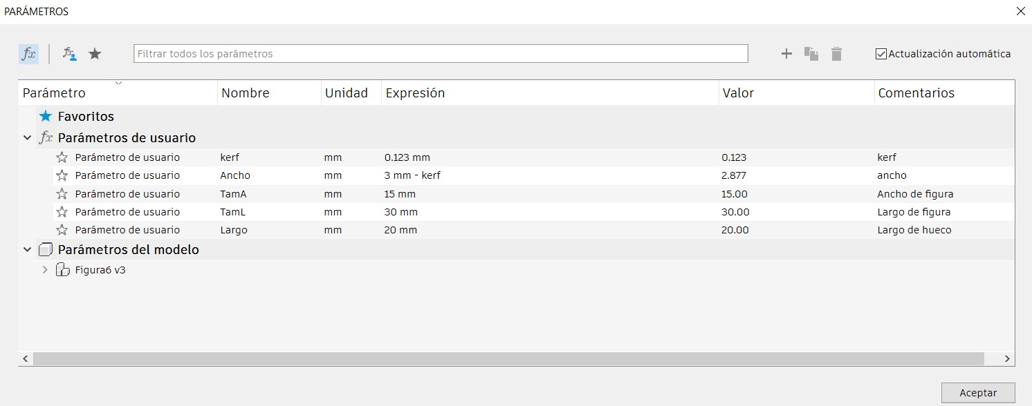
Figure 7. Triangle.
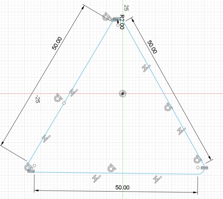
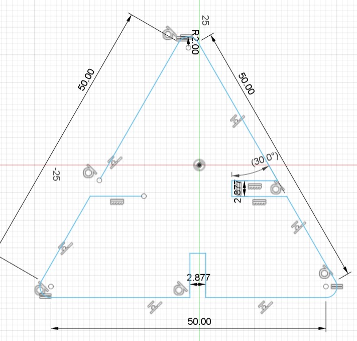
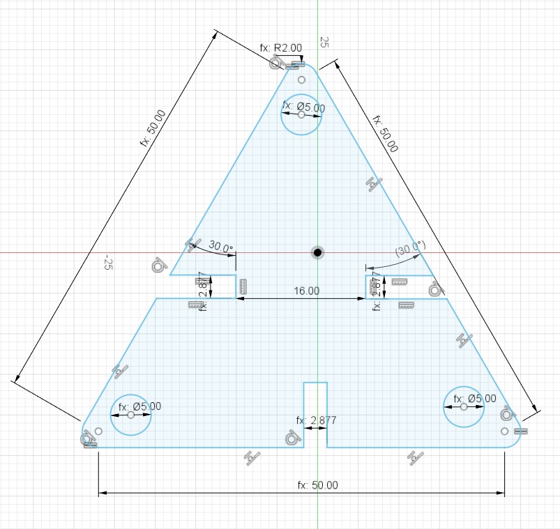
Figure 7 parameters:
How to export the files in Fusion 360?
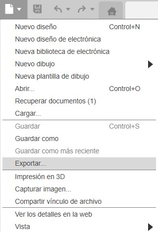
Step 1. Select the export option in the upper left corner.
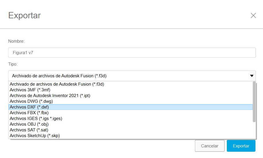
Step 2. We name the file and choose the .dxf format.
The .dxf format is preferred for laser cutting because of its wide compatibility with CAD/CAM software and its ability to preserve accuracy in design details, facilitating the transfer and production of complex parts.
Step 3. Next we save the file to some location on our computer.

Step 4. Select the export option and wait.
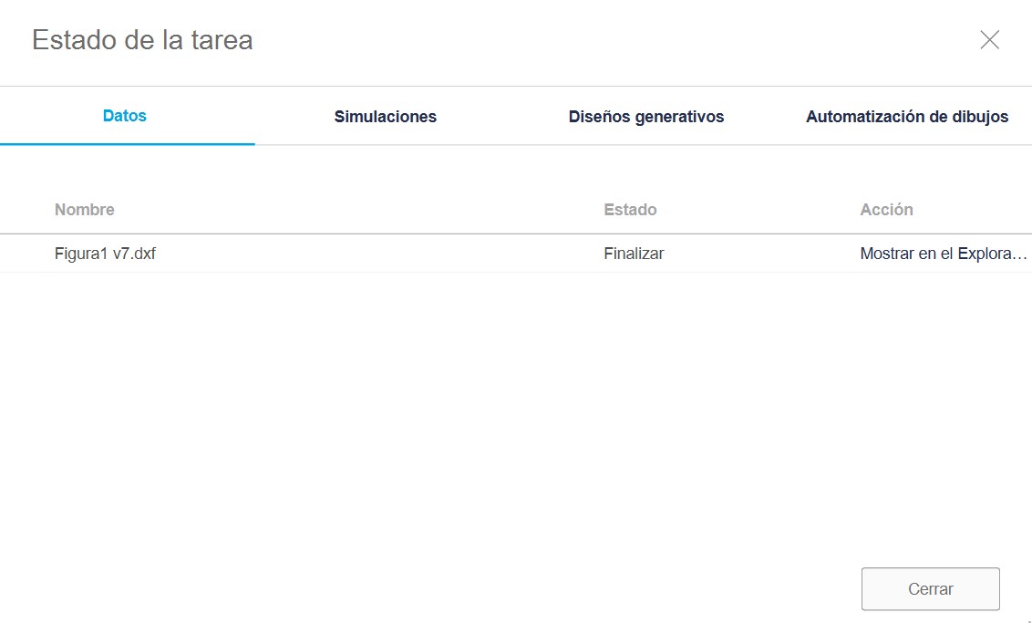
Step 5. For the last step we select all the files in .dxf format and transfer them to a USB flash drive.
Development of Construction Kit on Laser Machine
To use the laser machine, I utilized the machine software. Detailed steps for turning on and using the machine are available in the group activity, which you can consult through this link.
Before cutting my figures on the laser machine, I conducted tests to adjust the speed and power, considering the thickness of the 3 mm MDF used. Initial parameters:
- Maximum power: 60
- Minimum power: 50
- Speed: 25
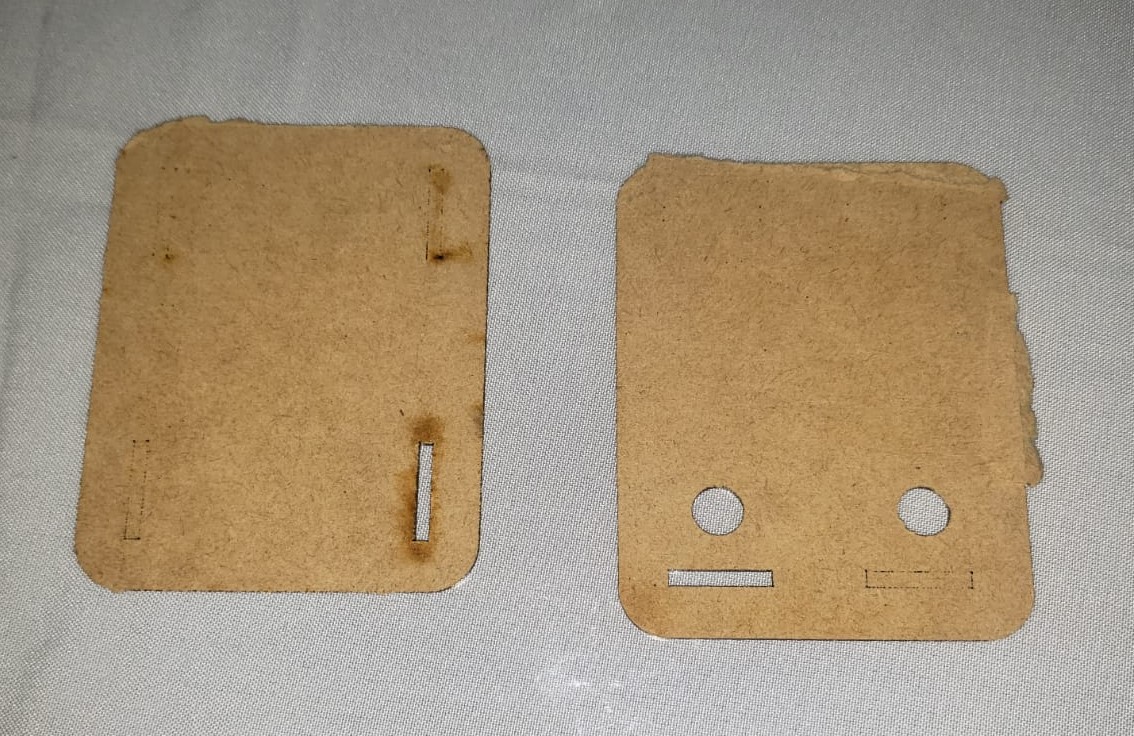
Initial tests were not successful, as shown in the picture below. The machine did not cut the pieces properly, so I increased the power values by 15 and reduced the speed to 20, achieving better results:
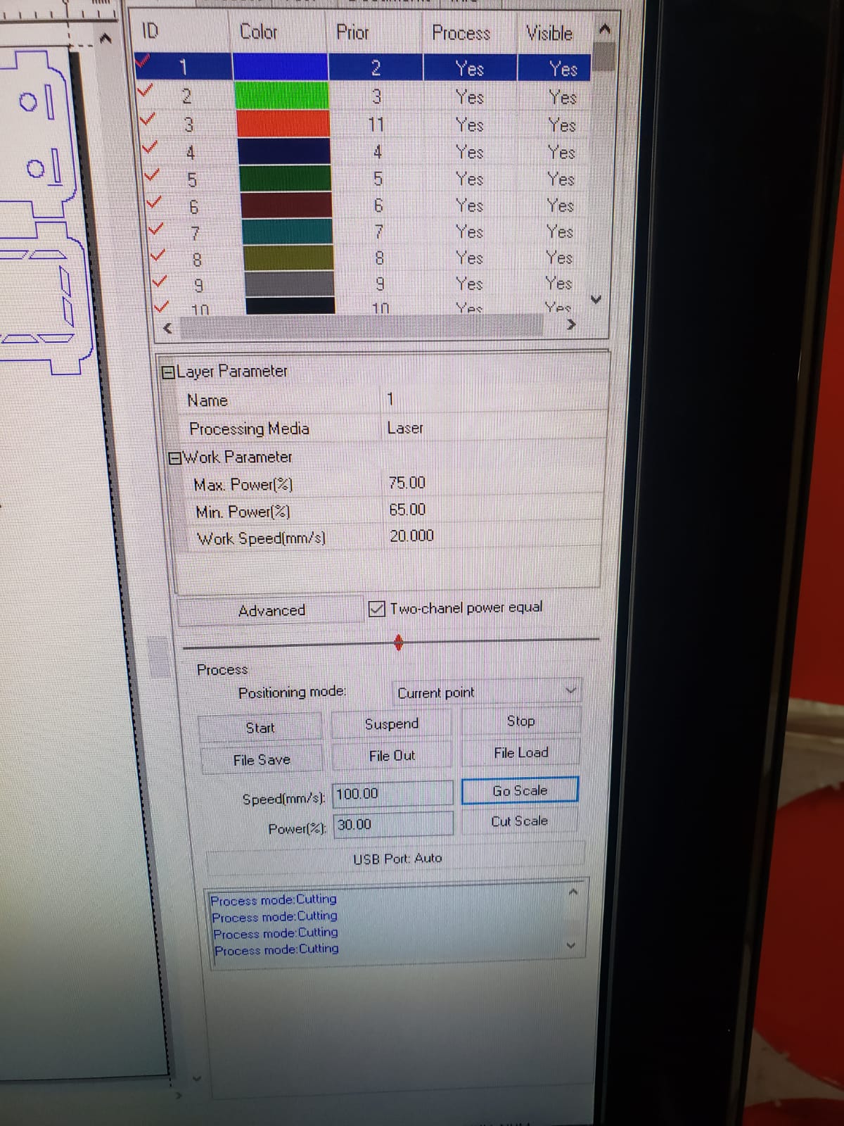
Final cutting parameters:
- Maximum power: 75
- Minimum power: 65
- Speed: 20
The final result:
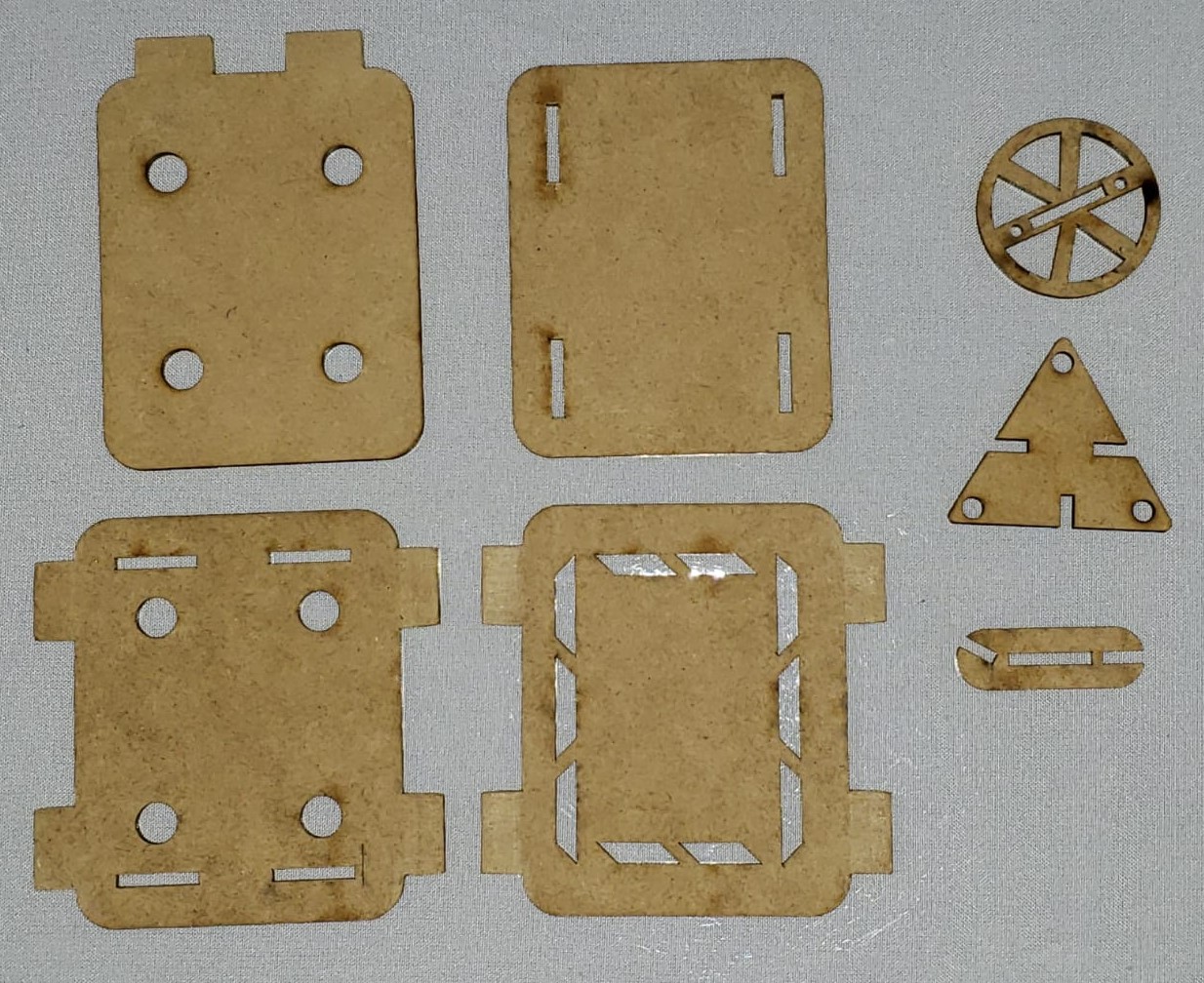
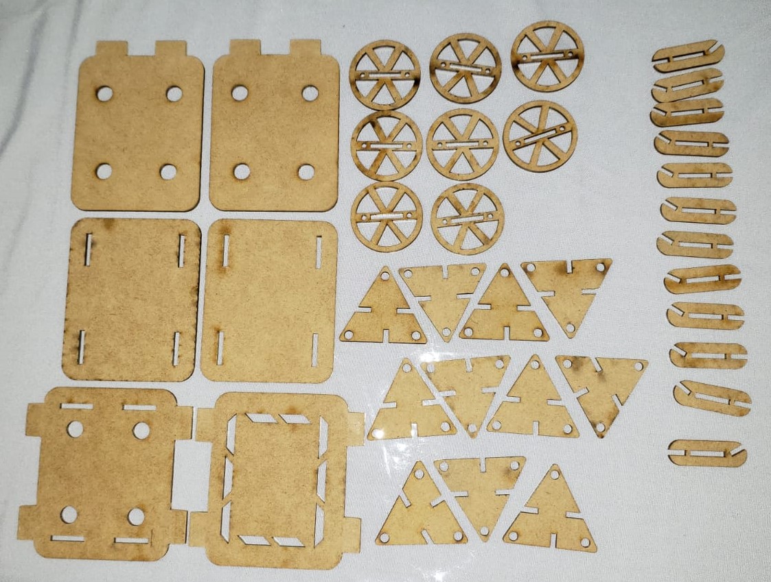
All the pieces I cut:
The figures I assembled with my construction kit are as follows:
Figure 1:
This figure is a car, in the back I put some thrusters.
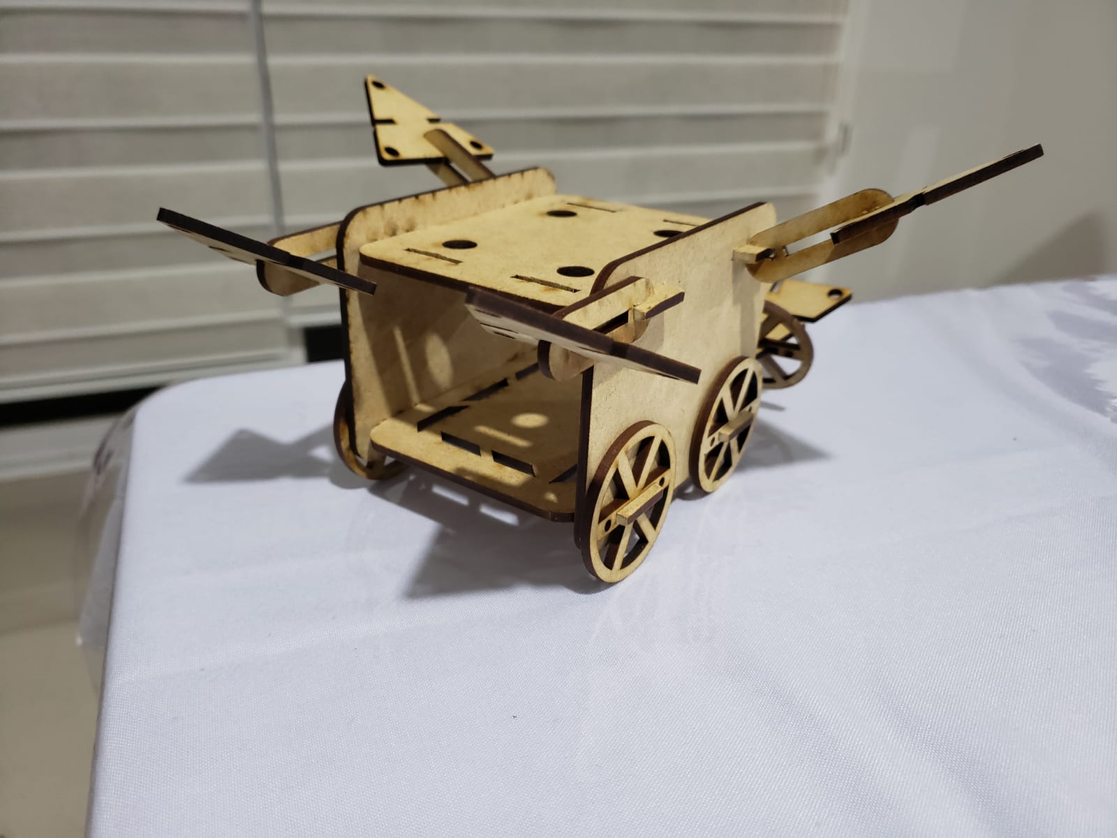
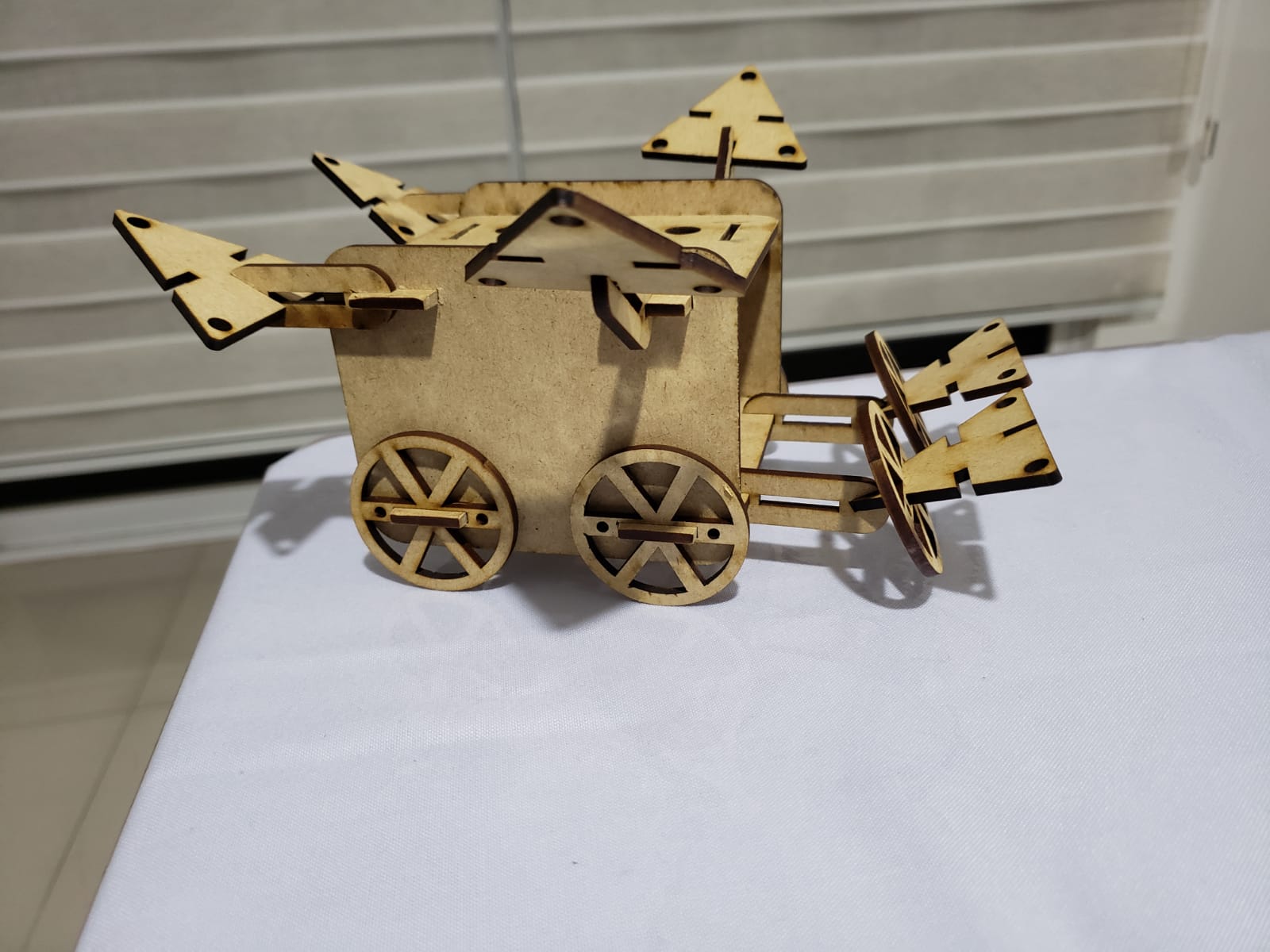
Figure 2:
This figure is a cell phone holder, I changed the wheels for the triangles and put some arms with elbows to hug the cell phone.
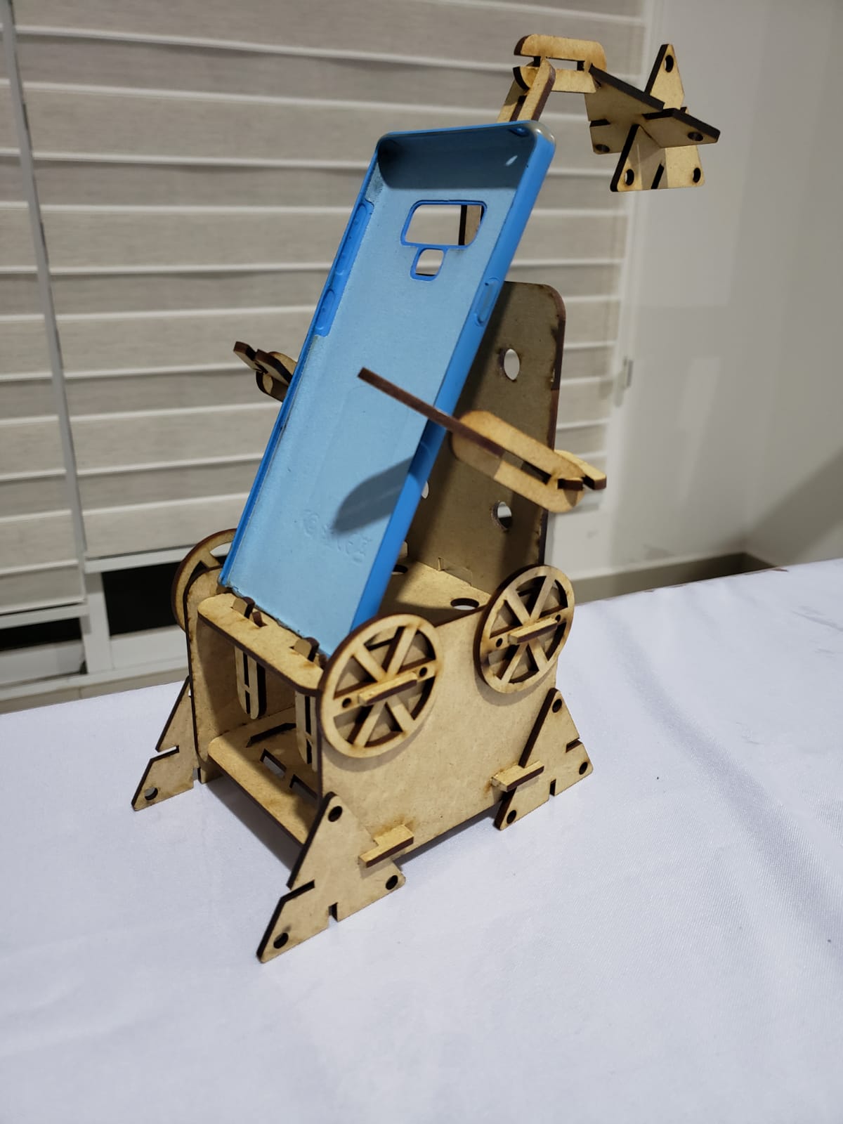
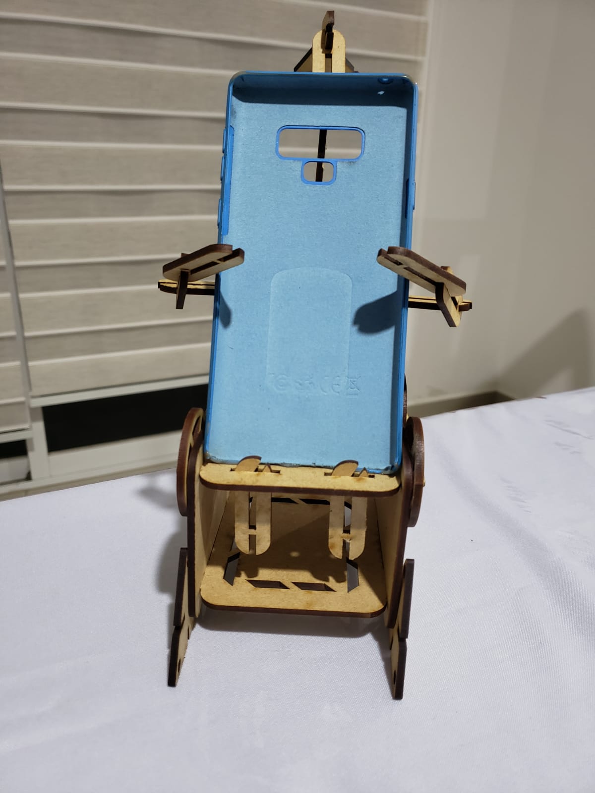
Figure 3:
These figures are airplanes, made with triangles, elbows and wheels.
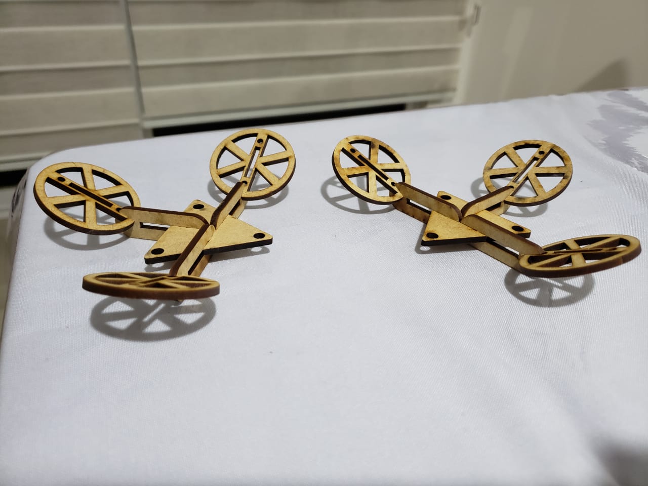
Figure 4:
This figure is a combat ship, the wheels represent the propellers of the ships and I put elbows with triangles as the weapons.
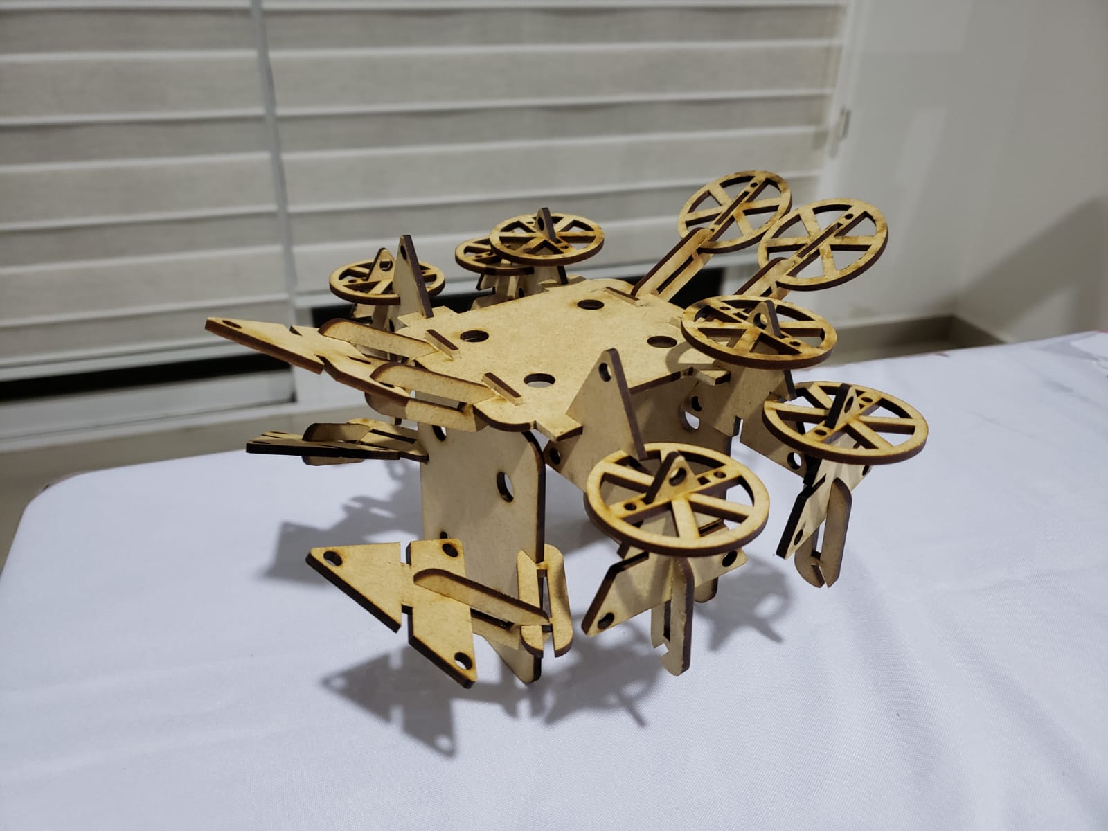
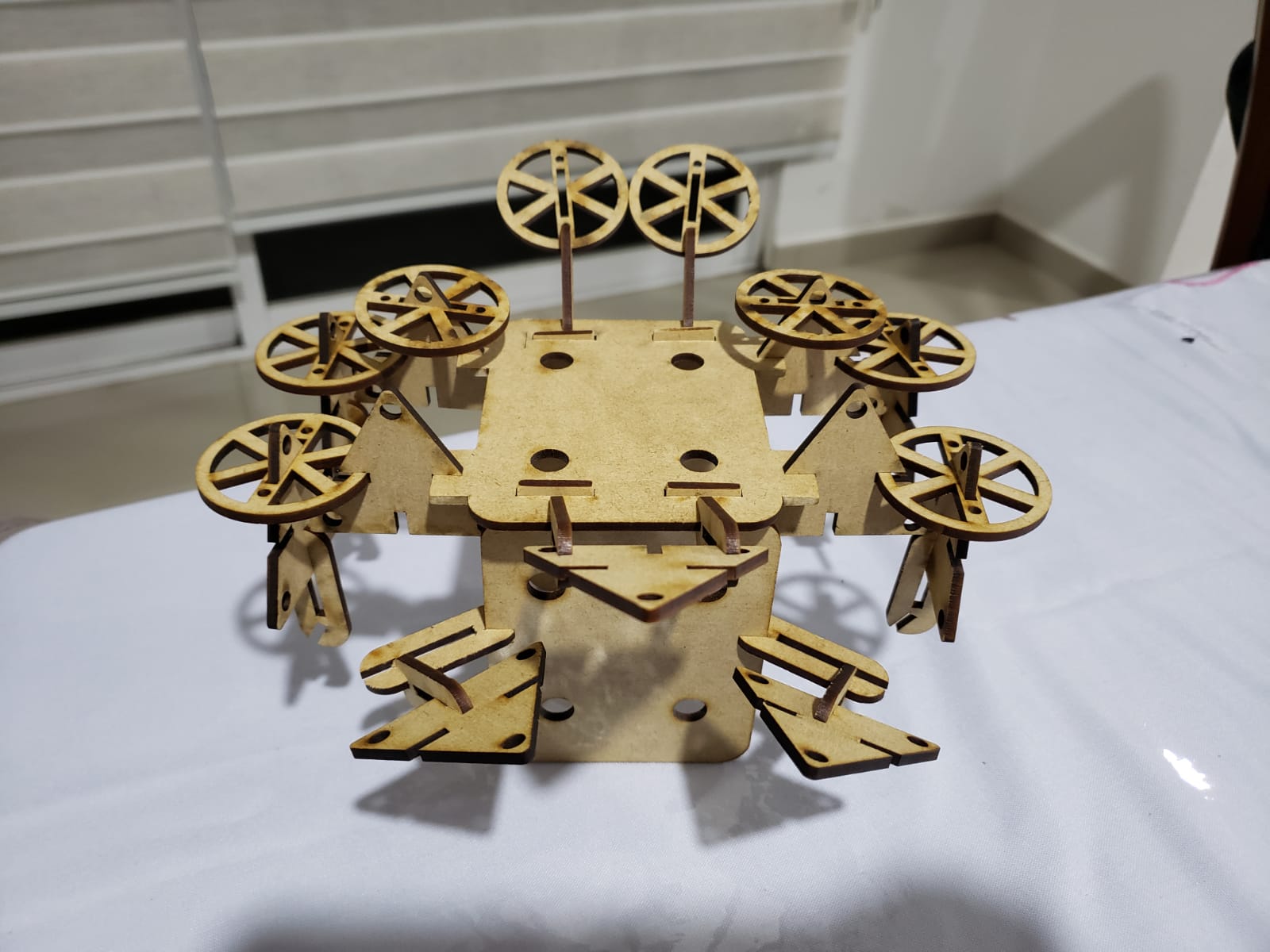
Figure 5:
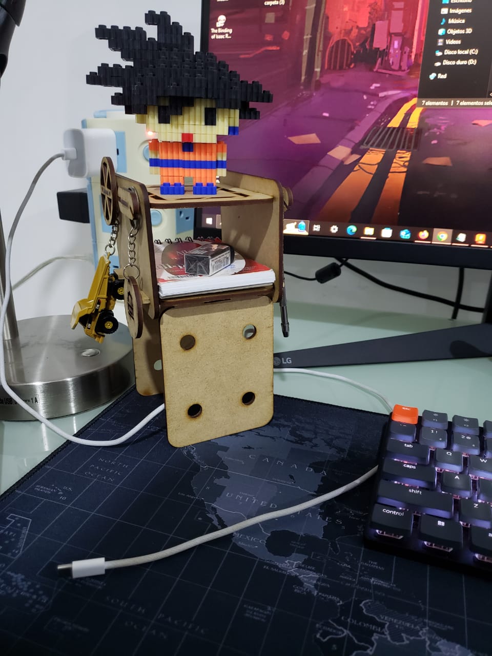
Finally, I made this figure. It is a stand for my setup, I can put keys, key rings, figures, small things, etc.
Individual assignment: vinyl cutter
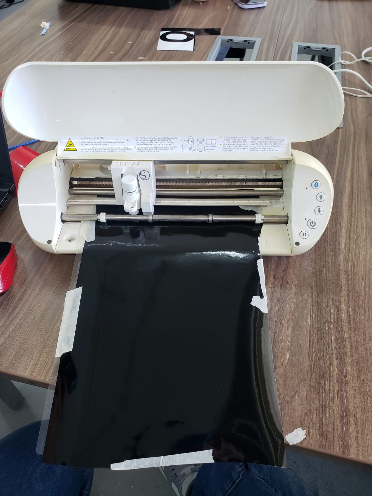
The machine I used to make the vinyl cut is the Silhouette model. You can find it on Amazon in the following link.
To use this machine you must download the software to your computer. You can consult the software in the following link.
The Silhouette Portrait 3 is a cutting plotter that is small in size and price, but big on features and functions. The Silhouette Portrai cutting plotter is the best value electronic cutting machine on the market. It allows the use of the new Silhouette AutoBlade 2 auto-adjusting knife (compatible with Cameo 4), as well as blades from previous models using an adapter set sold separately.
Machine features:
- Cutting mat 8" x 12''.
- AutoBlade.
- Silhouette Studio software.
- Adapter for Silhouette drawing pens.
- Power and USB cable.
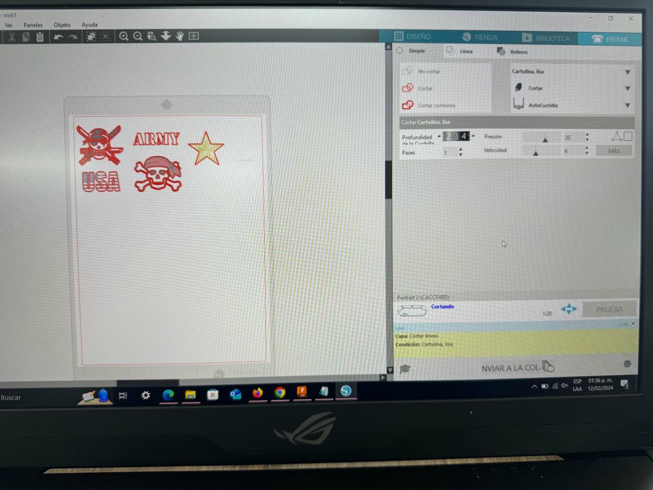
After downloading the software to my computer, I looked for an image to cut. The design I chose was as follows:

After inserting the image into the software as shown in the image the process starts:
To use the machine, a material below the paper must be used.
Machine working:
Result:
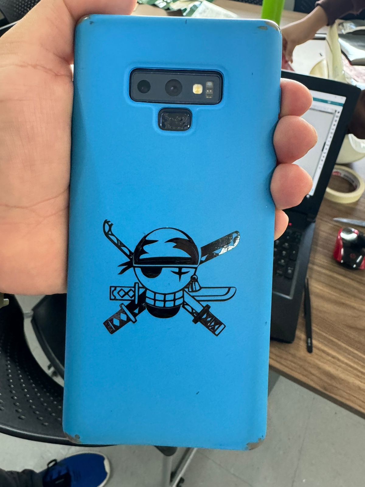
I carefully peeled off the image and placed it in my cell phone case.