
11. Input Devices
Overview
This week's task was to test various sensors, which is crucial for my final project since I intend to use them to control the growth of plants. You can consult the group assignment in the following link.
What components did I use for this week?
For my final project at Fab Academy, I have decided to focus on optimizing plant growth by constantly monitoring their environment. This week, which focused on working with input devices, was the perfect opportunity to select and test two types of sensors essential to my research. The first sensor I chose is the DHT11, an ambient humidity and temperature sensor that is crucial for maintaining the ideal conditions that plants require. The second sensor is a soil hygrometer that evaluates soil moisture, a determining factor for proper nutrient and water uptake by plants. The choice of these sensors is based on their accuracy, cost-effectiveness and ease of integration with automated systems, which will allow detailed monitoring and adjustment of growing conditions in real time.
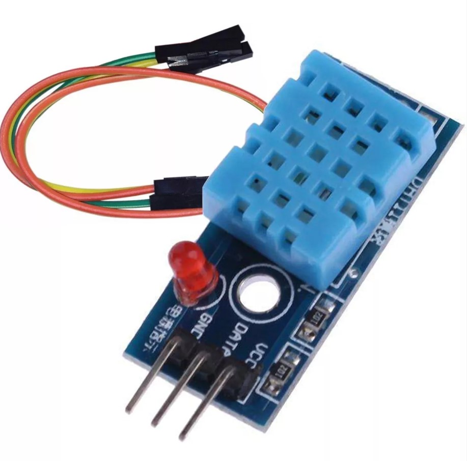
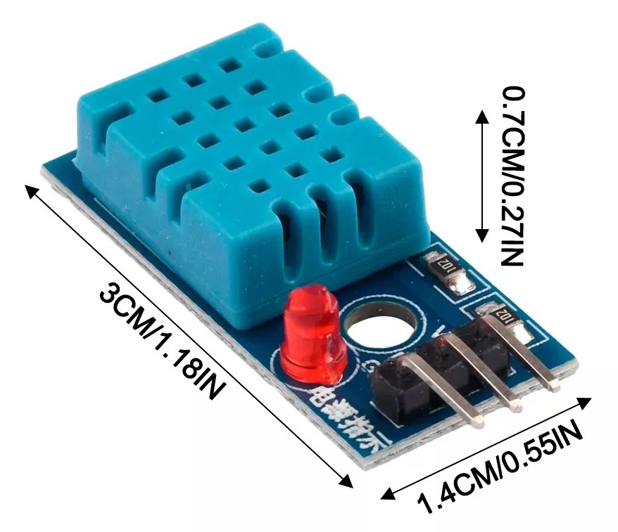
Temperature and humidity sensor (DHT11)
This sensor is characterized by having a calibrated digital signal, which ensures high quality and reliability over time, since it contains an integrated 16-bit converter and consists of two resistive sensors (NTC and humidity).
It has excellent quality and fast measurement response, it can measure humidity in the range 20% - approx. 95% and temperature in the range 0ºC - 50ºC.
The communication protocol is through a single wire (1-wire protocol), thus making the integration of this sensor in our projects quick and easy. It also has a small size, low power consumption and the ability to transmit the signal up to 20 meters away.
Features:
Operating voltage
3.5 V to 5.5 V
Humidity measurement range
20% to 90% RH
Humidity measurement error
±5%
Humidity measurement resolution
1% RH
Temperature measuring range
0 ºC to 50 ºC
Temperature measurement error
±2 °C
Temperature measurement resolution
1 ºC
Signal transmission range
20 meters
The above characteristics are the most important ones of the DHT11 sensor, however, if you want to consult more information about this sensor, you can do it in the following link.
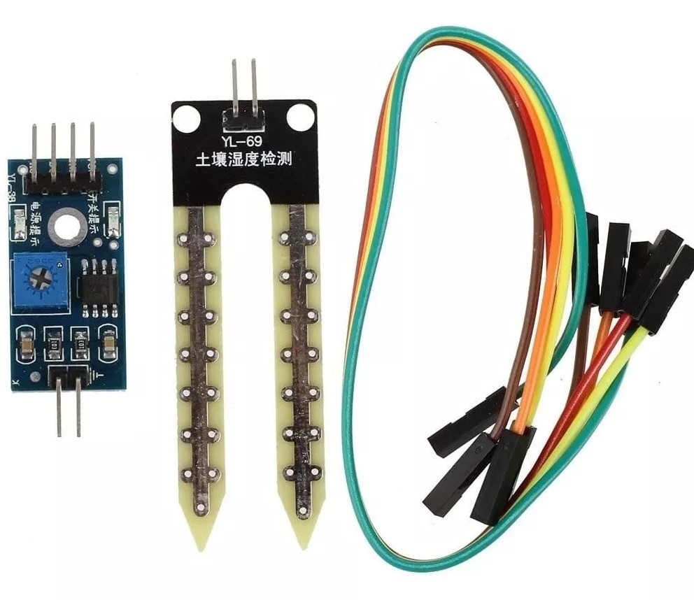
Soil moisture sensor (hygrometer) FC-28
A soil hygrometer FC-28 is a sensor that measures soil moisture. They are widely used in automatic irrigation systems to detect when it is necessary to activate the pumping system.
The FC-28 is a simple sensor that measures soil moisture by the variation of its conductivity. It is not accurate enough to make an absolute soil moisture measurement, but it is not necessary to control an irrigation system.
The FC-28 is distributed with a standard measuring plate that allows to obtain the measurement as an analog value or as a digital output, activated when the humidity exceeds a certain threshold.
The values obtained range from 0 submerged in water, to 1023 in air (or in very dry soil). A slightly moist soil would give typical values of 600-700. A dry soil will have values of 800-1023.
The digital output triggers when the humidity value exceeds a certain threshold, which we adjust by means of the potentiometer. Therefore, we will get a LOW signal when the soil is not wet, and HIGH when the humidity exceeds the setpoint value.
The specific value will depend on the type of soil and the presence of chemical elements, such as fertilizers. Also, not all plants require the same humidity, so it is best to do a small calibration in the actual field.
Features:
Operating voltage
3.3 V to 5 V
Operating current
10 mA to 35 mA
Humidity detection range
Variable, depending on calibration
Sensitivity
Adjustable by potentiometer
Response time
< 1 second
Operating temperature
-40 °C to 70 °C
Analog output
0 to 4.2 V, increases with decreasing soil moisture
Digital output
Activated when soil moisture falls below the set threshold
The above features are the most important of the FC-28 sensor, however, if you want to see more information about this sensor, you can do it in the following link.
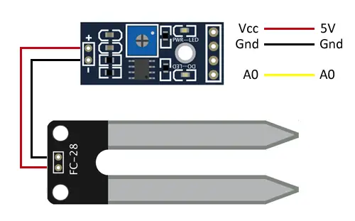
The image above shows the pinout of the sensor, to make the connections correctly.
Testing the sensors on my PCB
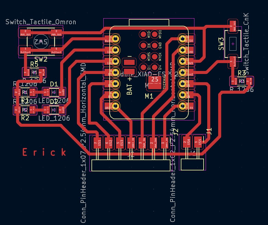
The PCB I used for this week was the one I made in week 8 of "electronic design". You can check my week 8 page at the following link. The microcontroller I used is a Xiao ESP32. The following image is the design of my PCB in KiCad, I used it to know which pins to use, it was very helpful.
Testing humidity and temperature sensor (DHT11):
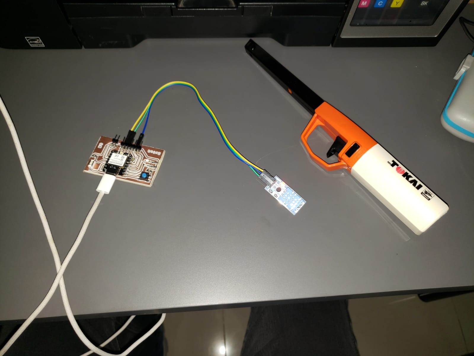
The connection was quite easy. I used pins 2 and 3 for voltage and ground and pin 6 for programming the sensor. To test the sensor I used a cooking gas lighter to increase the temperature.
This code is designed to read the humidity and temperature of an environment. At startup, it establishes serial communication and activates the DHT sensor. In each cycle of the main loop, the program waits two seconds to avoid too frequent readings that can affect the accuracy of the sensor. It then performs the humidity and temperature readings; if any of the readings fail, it prints an error message and exits the function. If the readings are successful, it displays the humidity and temperature values in degrees Celsius on the serial monitor.
Here my code:
    // Include the DHT sensor library.
    #include "DHT.h"

    // Define the digital pin and type of DHT sensor.
    #define DHTPIN D4 // Data pin connected to the DHT11
    #define DHTTYPE DHT11 // Specifies the DHT sensor type

    // Create a DHT sensor object.
    DHT dht(DHTPIN, DHTTYPE); // Initializes the DHT sensor

    void setup() {
        Serial.begin(115200); // Begins serial communication
        dht.begin();          // Starts the DHT sensor
    }

    void loop() {
        // Waits a few seconds between measurements (DHT sensors should not be read more than once every 2 seconds)
        delay(2000);

        // Reads the humidity percentage
        float humidity = dht.readHumidity();
        // Reads the temperature in Celsius degrees
        float temperature = dht.readTemperature();

        // Checks if the readings failed and if so, exits the loop function.
        if (isnan(humidity) || isnan(temperature)) {
        Serial.println("Failed to read from DHT sensor!");
        return;
        }

        // Prints the results to the serial monitor
        Serial.print("Humidity: ");
        Serial.print(humidity);
        Serial.print("%  Temperature: ");
        Serial.print(temperature);
        Serial.println("°C");
    }
Result:
Testing the soil moisture sensor:
To use the soil moisture sensor I used a plant I had in my house (it's the only one I have hahaha). First I used it without water and then with water.

In this code, two pins are defined: one to read the sensor status (input) and one to control the sensor power supply (output), allowing to activate or deactivate the sensor to save energy. In the setup, the control pin is initialized as output and the sensor is activated. In each cycle of the loop, the sensor value is read: if the result is HIGH, it is interpreted as dry soil and "Dry soil" is printed; if it is LOW, it is interpreted as wet soil and "Moist soil" is printed. The cycle repeats every second, providing regular updates on the state of the soil.
Here my code:
    // Replace 4 with the digital GPIO pin you will use
    #define SOIL_MOISTURE_SENSOR_PIN D3
    // If you want to control the power of the sensor
    #define SOIL_MOISTURE_SENSOR_POWER 23

    void setup() {
        pinMode(SOIL_MOISTURE_SENSOR_PIN, INPUT); // Set the sensor pin as input
        pinMode(SOIL_MOISTURE_SENSOR_POWER, OUTPUT); // Control the power of the sensor
        digitalWrite(SOIL_MOISTURE_SENSOR_POWER, HIGH); // Turn on the sensor
        Serial.begin(115200);
    }

    void loop() {
        int sensorValue = digitalRead(SOIL_MOISTURE_SENSOR_PIN); // Read the sensor value
        if (sensorValue == HIGH) {
        Serial.println("Dry soil");
        } else {
        Serial.println("Moist soil");
        }
        delay(1000); // Wait one second between readings
    }
Result:
Plant without water
Plant with water: