Week10-Machine Design
Mechanical Design (part 1 of 2)
Group assignment:
- Design a machine that includes mechanism + actuation + automation + application
- Build the mechanical parts and operate it manually
- Document the group project
Individual assignment:
- Document your individual contribution
Machine Design (part 2 of 2) Group assignment:
- Actuate and automate your machine
- Document the group project
Individual assignment:
- Document your individual contribution
Checklist
- Documented the machine building process to the group page
- Documented your individual contribution to this project on your own website
- Linked to the group page from your individual page as well as from group page to your individual pages
- Shown how your team planned, allocated tasks and executed the project (Group page)
- Described problems and how the team solved them (Group page)
- Listed possible improvements for this project (Group page)
- Included your design files (Group page)
- You need to present your machine globally and/or include an aprox. 1 min video (1920x1080 HTML5 MP4)+ slide (1920x1080 PNG) (Group page)
Group assignment
What did I learn?
During the entire structural design process, I gained a lot of experience and faced several challenges. Initially, I designed the spindle fixture to be too thin, which resulted in insufficient overall strength. Additionally, I chose a low-cost motor, which caused significant noise and vibration. To address these issues, I thickened the spindle fixture and replaced the motor with a higher-performance one. I also added a metal cylinder to the spindle structure to improve its rigidity.
Individual assignment
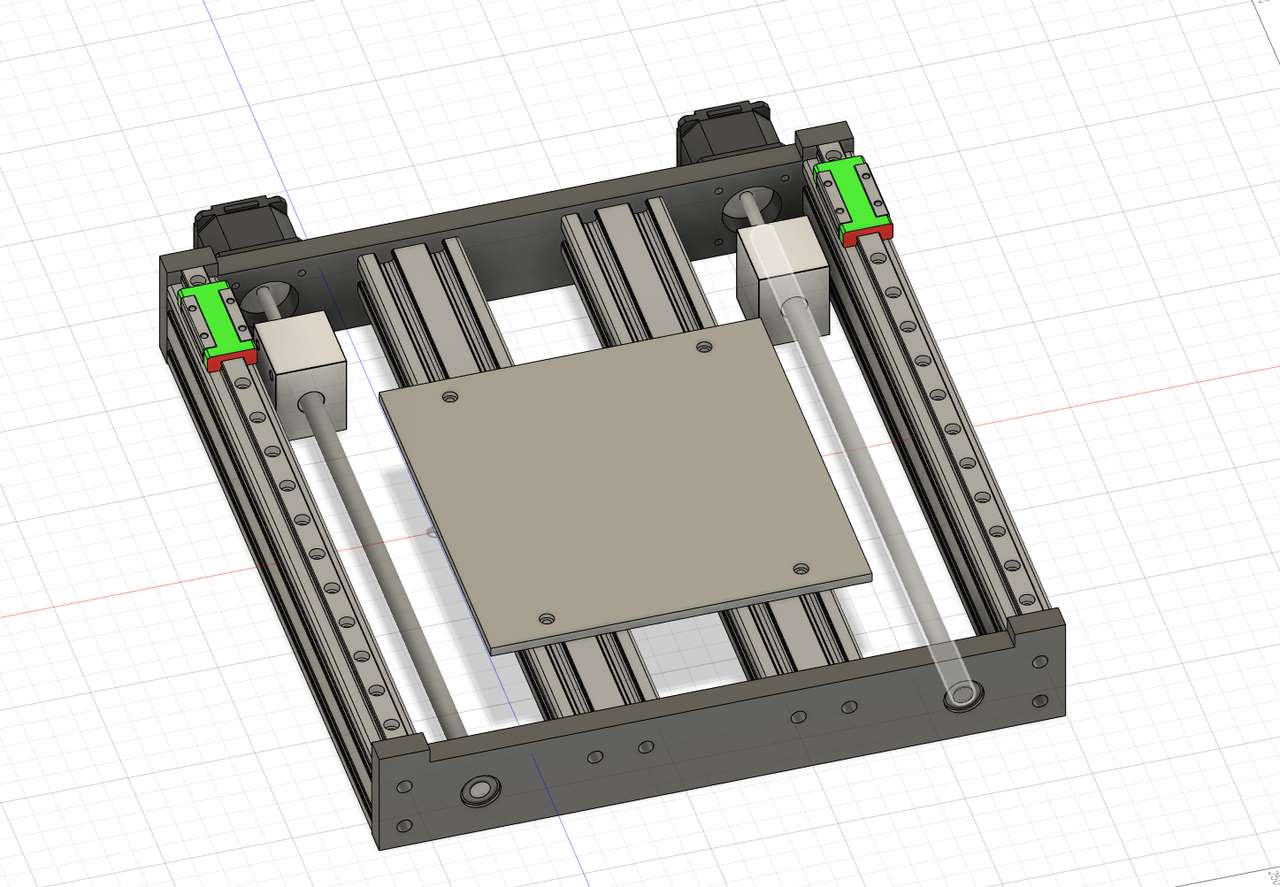
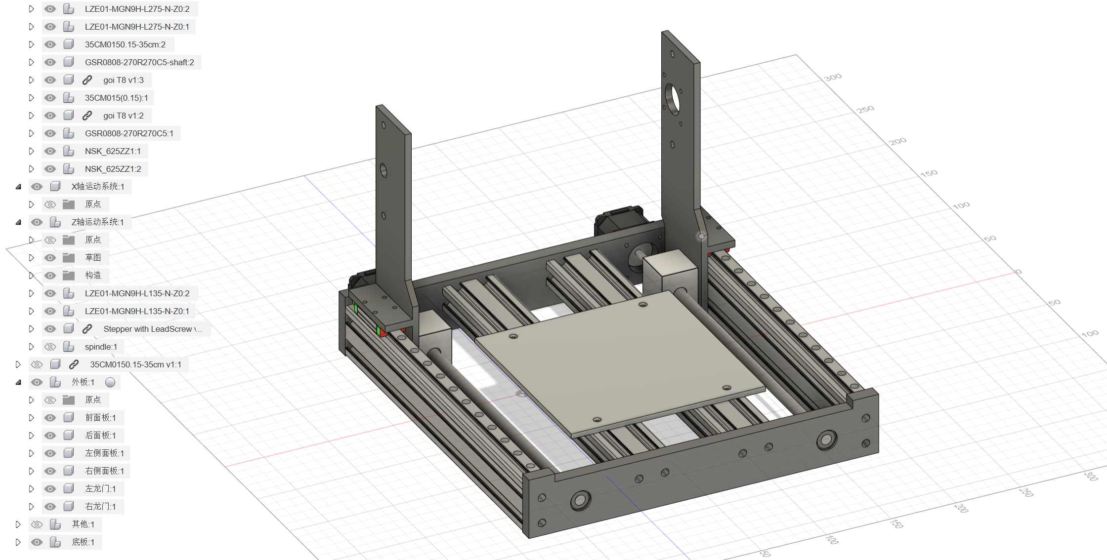
In this week’s tasks, I’m responsible for the modeling part.
Since we’re at a STEM education center in Shanghai, our team’s idea is to create a small CNC machine specifically for milling PCBs, intended for educational purposes.
At first, the plan for the CNC’s Y-axis was to move the platform back and forth. After completion, I found that the distance of movement was too large, which doesn’t meet our requirement for a small distance.
So I changed it to a plan where only the gantry moves.
There’s a conversion seat on the lead screw, connected to the slider with printed parts. This completes the motion part.
For the spindle part, I used injection-molded part found online and connected them initially with printed parts.
We encountered some issues during the process. Since the lead screw was custom-length, but the manufacturer mixed up my order, we couldn’t complete the assembly. Currently, we’re still waiting for the shipment to arrive.
Four months later…
During this overhaul, we encountered many issues.
For example, the traces we initially cut were very rough. Later, we discovered that the tool holder we were using was misaligned.
After we replaced the entire spindle motor from a 795 to a more professional 200W motor, we found a significant improvement. The noise was reduced, and the vibrations were less, but this came with an additional cost of 200 RMB. However, this decision was definitely worth it.
Then we found that the Z-axis strength was not sufficient during testing. To address this, I replaced the original 6mm guide rod with a 10mm guide rod, used longer bearings, and reinforced the printed parts. Thanks to JLCFA for providing economical and useful industrial components; they are much cheaper than the Misumi parts I used before in China.
Because the equipment is now being sold as commercial equipment, I cannot disclose detailed structural information.
However, we are currently working on the development of the second generation. Once it’s completed, we will open source the first generation.


