Week09-output Devices
Group assignment:
- Measure the power consumption of an output device.
- Document your work on the group work page and reflect on your individual page what you learned.
Individual assignment:
- Add an output device to a microcontroller board you’ve designed and program it to do something.
CHECKLIST
- Linked to the group assignment page.
- Documented how you determined power consumption of an output device with your group.
- Documented what you learned from interfacing output device(s) to microcontroller and controlling the device(s).
- Linked to the board you made in a previous assignment or documented your design and fabrication process if you made a new board
- Explained the programming process/es you used.
- Explained any problems you encountered and how you fixed them.
- Included original source code and any new design files.
- Included a ‘hero shot of your board.
Group assignment
What did I learn?
In this week’s group work, I learned how to use the GPS305D power supply for testing. By setting the voltage to 5V and adjusting the current, we tested a 3V-6V motor. The motor did not require specific polarity for connection, making the operation simpler. The final test results showed that under normal operating conditions, the voltage remained stable at 5V, while the current varied according to the load, dropping from 0.13A to 0.05A. This test helped me better understand the voltage and current adjustment modes of the power supply and how to adjust the output parameters based on actual requirements.
Individual assignment
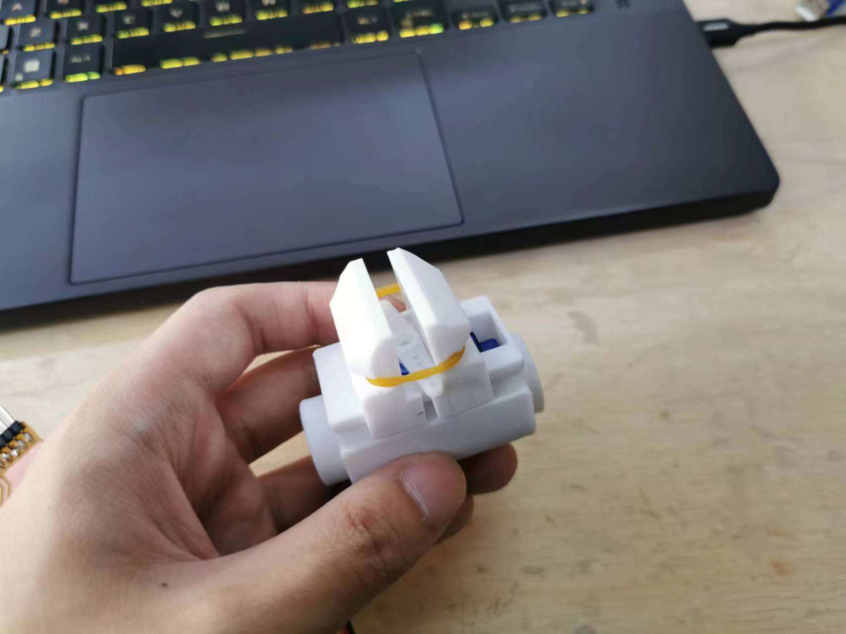
I wanted to make a small claw, so I searched for relevant models on Thingiverse. Eventually, I found a model of a mechanical arm’s claw.
This is link:https://www.thingiverse.com/thing:6313449


I used a 3D printer to print it and i used PETG as the printing material, and I believe its strength is sufficient.
After printing was completed, I assembled it.
BOM:
| Model number | number |
|---|---|
| servo | 1 |
| m2*5 SHCS | 2 |
| Rubber bands | 1 |
I started debugging the code.
I used the built-in buttons on my motherboard to control the servo motor.
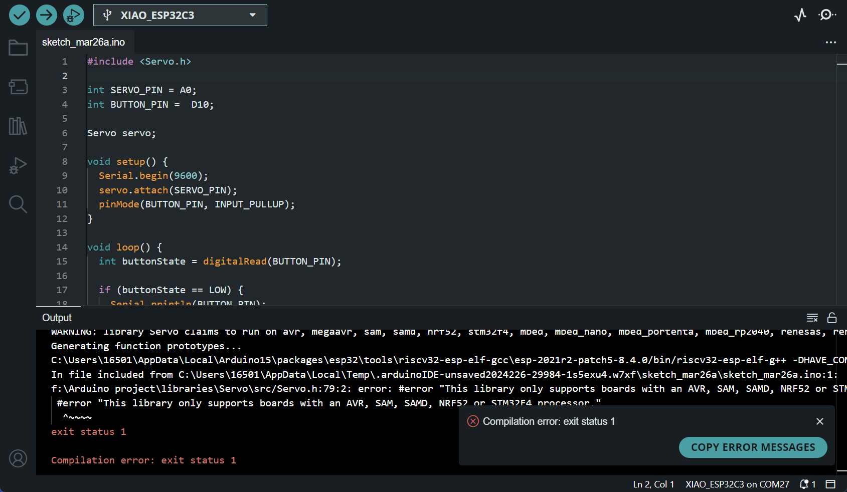
Oh no, I failed. The reason is because the servo library does not support ESP32.
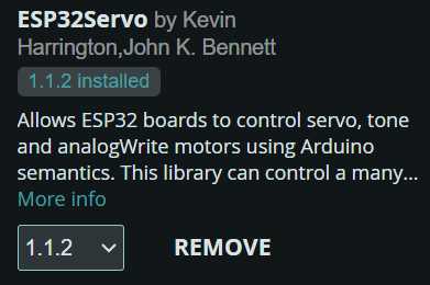
I tried switching to a servo library for ESP32, then I read through the example code it provided. Afterward, I modified my program.
It gave another error. After checking the Seeed Xiao’s wiki, the solution provided was to hold down the boot button until the upload is complete.
Oh, it finally uploaded successfully.


sorce file:
#include <ESP32Servo.h>

int SERVO_PIN = A0;
int BUTTON_PIN =  D10;

Servo servo;

void setup() {
  Serial.begin(9600);
  servo.attach(SERVO_PIN);
  pinMode(BUTTON_PIN, INPUT_PULLUP);
}

void loop() {
  int buttonState = digitalRead(BUTTON_PIN);

  if (buttonState == LOW) {
    Serial.println(BUTTON_PIN);
    servo.write(25); // 舵机转到 25 度
    delay(100);      // 给舵机时间转动
  } else {
    servo.write(0);  // 舵机转到 0 度
  }
}

