Week11-Input Devices
Group assignment:
- Probe an input device(s)’s analog levels and digital signals
- Document your work on the group work page and reflect on your individual page what you learned
Individual assignment:
- Demonstrate workflows used in sensing something with input device(s) and MCU board
Checklist
- Linked to the group assignment page.
- Documented what you learned from interfacing an input devicels to your microcontroler and optionaly, how the physical property relates to the measured results.
- Documented your design and fabrication process or linked to the board you made in a previous assignment.
- Explained the programming process(es) you used.
- Explained any problems you encountered and how you fixed them.
- Included original design files and source code.
- Included a ‘hero shot of your board.
Group assignment
We used a button and a potentiometer for measurement.
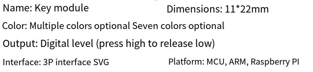
button
A button is a type of switch device commonly used to control the on and off states of a circuit. Its basic principle can be explained through the following aspects:
1. Mechanical Principle The mechanical principle involves the structural design of the button. Typically, a button consists of a movable part (such as a button cap) and a fixed part (such as a button base). When the button is pressed, the cap moves downward, pushing the internal mechanical structure (such as springs or conductive plates), causing the circuit to connect or disconnect. When the button is released, the spring or other reset mechanism pushes the cap back to its original position, restoring the initial state.
2. Electrical Principle The electrical principle involves how the button controls the flow of current in a circuit. There are mainly two types of electrical buttons:
- Normally Open (NO) Button: The circuit is open (disconnected) when the button is not pressed; pressing the button closes (connects) the circuit.
- Normally Closed (NC) Button: The circuit is closed (connected) when the button is not pressed; pressing the button opens (disconnects) the circuit.
1. Working Process When the button is pressed, the following processes may occur:
- In a normally open button, the conductive plate or metal spring contacts, completing the circuit and allowing current to flow.
- In a normally closed button, pressing the button separates the conductive plate or metal spring, breaking the circuit and stopping the current flow.
4. Contact Materials The internal conductive plates of a button are usually made of materials with good conductivity, such as copper or silver, to ensure low resistance and reliable current flow. To increase durability, the contact points are sometimes coated with anti-corrosion materials.
5. Usage Scenarios Buttons are widely used in various electrical devices, such as household appliances, industrial controls, computer keyboards, and more. Depending on the scenario, buttons may have different designs and specifications, such as waterproof buttons or dustproof buttons, to meet specific environmental requirements.
Through these principles and processes, buttons effectively control the flow of current, allowing for the control and operation of devices.
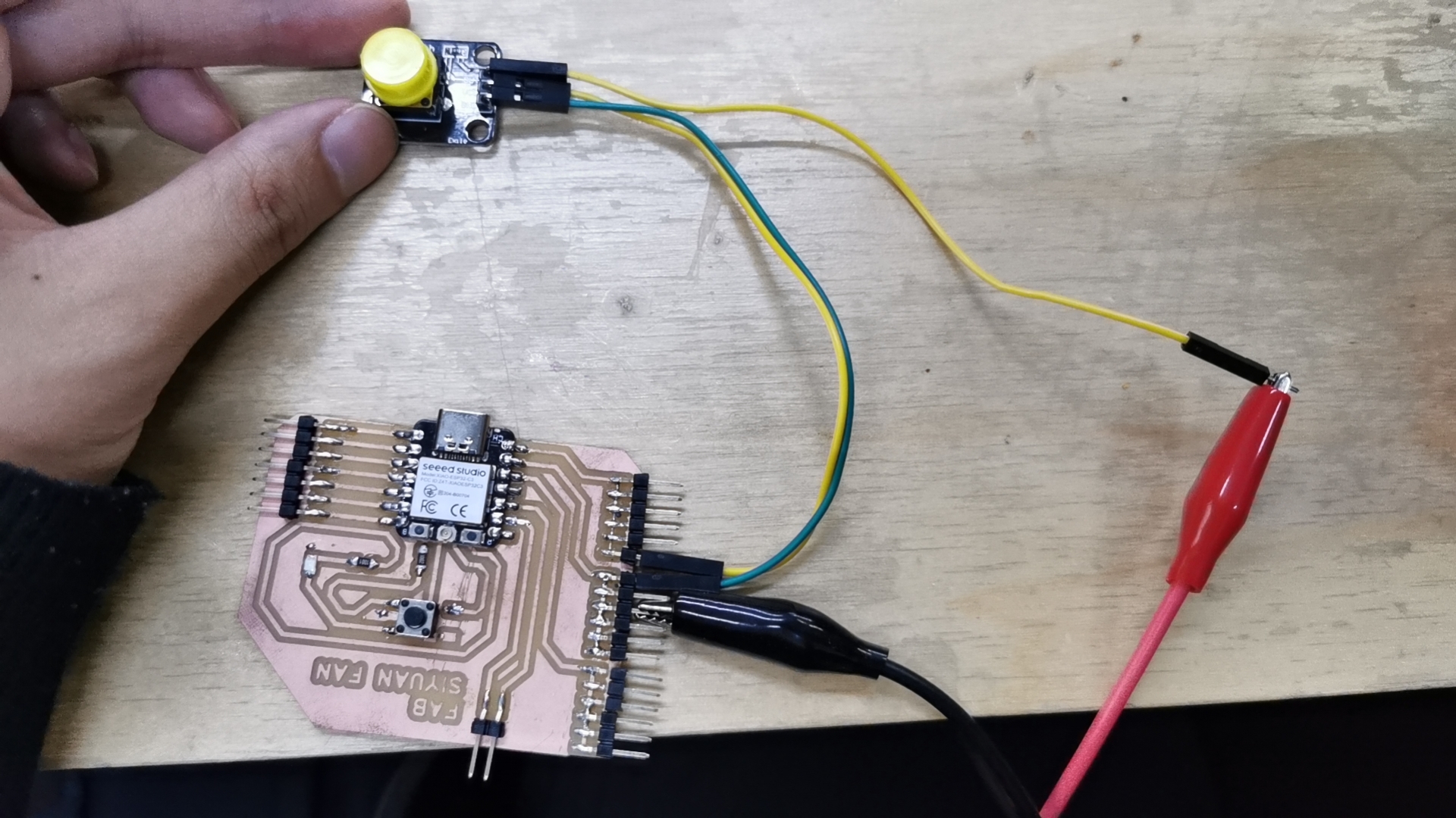
I connected the button to my development board and the oscilloscope to the button’s “out” pin.
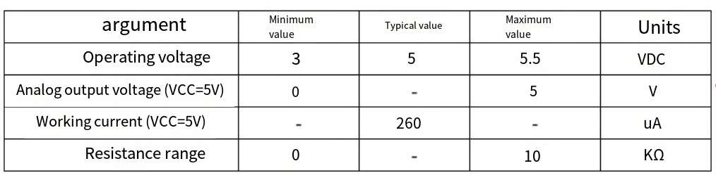
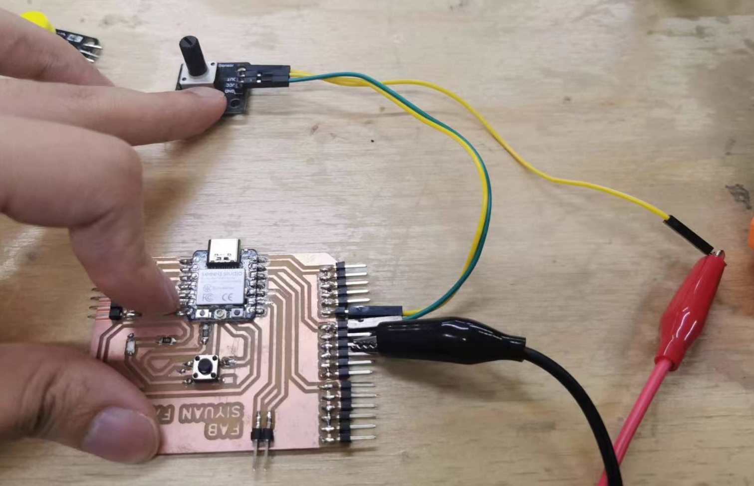
potentiometer
A potentiometer is a variable resistor that can change its resistance value by adjusting its knob or slider, thereby regulating the voltage and current in a circuit. The working principle of a potentiometer can be explained through the following aspects:
1. Structural Principle The basic structure of a potentiometer includes three main parts:
- Resistive Element: Typically an arc-shaped or linear resistive material.
- Sliding Terminal (Wiper): A movable terminal that can be adjusted along the resistive element.
- Fixed Terminals: Two fixed terminals connected at each end of the resistive element.
2. Working Principle The working principle of a potentiometer is based on Ohm’s Law and the voltage divider principle. By adjusting the position of the sliding terminal, the resistance value between the sliding terminal and the fixed terminals can be changed, thus adjusting the output voltage.
- Ohm’s Law: The relationship between resistance (R), voltage (V), and current (I) is given by ( V = IR ).
- Voltage Divider Principle: In a series circuit, the voltage is distributed proportionally according to the resistance values.
3. Adjusting the Resistance Value When the sliding terminal moves along the resistive element, its position determines the effective resistance value between the two fixed terminals. The process is as follows:
- When the sliding terminal is close to one fixed terminal, the resistance between that terminal and the sliding terminal is small, while the resistance between the sliding terminal and the other fixed terminal is large.
- Conversely, when the sliding terminal is far from one fixed terminal, the resistance between that terminal and the sliding terminal is large, while the resistance between the sliding terminal and the other fixed terminal is small.
4. Types of Potentiometers Depending on the structure and usage, potentiometers can be divided into several types:
- Rotary Potentiometers: Adjust the resistance value by rotating a shaft, commonly used for volume control.
- Linear Potentiometers: Adjust the resistance value by sliding a lever, commonly used in dimmers.
- Multi-turn Potentiometers: Have a multi-turn adjustment feature for precise control.
5. Usage Scenarios Potentiometers are widely used in various electronic devices and circuits, such as:
- Volume Control: Adjusting the volume of audio devices.
- Dimmers: Regulating the brightness of lights.
- Voltage Adjustment: Precisely controlling the voltage value in experimental circuits.
Through these principles and applications, potentiometers effectively control and adjust the voltage and current in circuits, meeting the needs of different devices and scenarios.
What did I learn?
This week, I learned the working principles and applications of buttons and potentiometers. A button serves as a switch, controlling the circuit’s on/off state through a mechanical structure. The most common types are Normally Open (NO) and Normally Closed (NC), and they are widely used in various electronic devices. A potentiometer, on the other hand, is an adjustable resistor, and by adjusting its sliding terminal, it changes the resistance value, thus altering the voltage and current in the circuit. By understanding their working principles, I am now able to design and control the signals and current in a circuit more effectively, and have applied measurements and use of buttons and potentiometers in my project.
Individual assignment
This week, I used a tilt sensor and a temperature sensor.
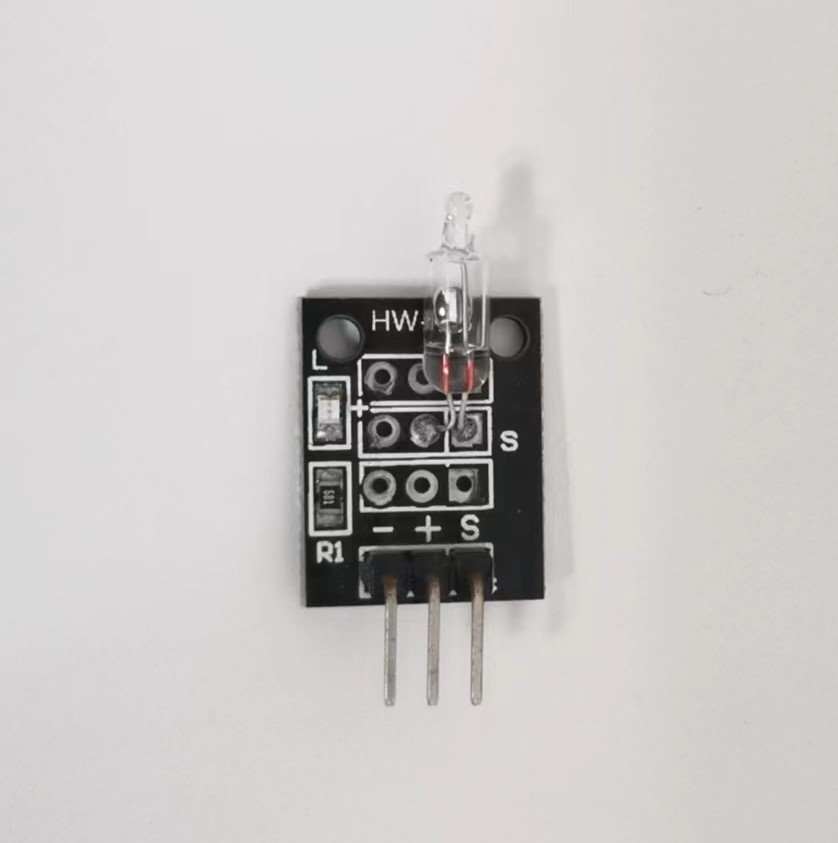
tilt sensor
A tilt sensor is a device used to detect the angle of tilt or inclination of an object relative to the direction of gravity. It measures the changes in orientation to determine the degree of tilt. Tilt sensors play a crucial role in various applications such as electronic devices, industrial control, aerospace, construction, and automotive systems.
1. Working Principle The working principle of a tilt sensor is based on the effect of gravity. It typically contains an element that can sense changes in the direction of gravity, such as a liquid, bubble, or accelerometer. When the sensor tilts, the position or state of the internal element changes, resulting in a change in the output signal, which reflects the tilt angle.
- Electrolytic Tilt Sensors: These contain a container filled with electrolytic fluid and two electrodes. When the sensor tilts, the area of the electrodes covered by the fluid changes, altering the capacitance or resistance value, which then outputs a signal corresponding to the tilt angle.
- Bubble Tilt Sensors: These include a sealed tube with a bubble and liquid inside. When the sensor tilts, the bubble moves within the tube, and its position change is detected and converted into an electrical signal.
- MEMS (Micro-Electro-Mechanical Systems) Accelerometers: These use micro-mechanical structures to sense changes in gravitational acceleration. When the sensor tilts, an internal tiny mass shifts, changing the capacitance or resistance, and outputs a corresponding electrical signal.
2. Applications Tilt sensors are widely used in the following fields:
- Consumer Electronics: Such as smartphones and tablets, used for screen auto-rotation, gaming controls, and other functions.
- Industrial Control: For monitoring and controlling the tilt of machinery or equipment, ensuring safe operation.
- Construction and Engineering: To monitor the tilt of buildings, bridges, and other structures, preventing deformation or collapse.
- Automotive Systems: For detecting the tilt angle of vehicles to achieve stability control and anti-rollover functions.
- Aerospace: For attitude control and navigation of aircraft.
3. Types and Technologies Tilt sensors can be divided into various types based on different detection principles and application requirements:
- Electrolytic Tilt Sensors: Suitable for applications requiring high precision.
- Bubble Tilt Sensors: Simple structure, suitable for general tilt detection.
- MEMS Accelerometers: Small size, low cost, widely used in consumer electronics and automotive systems.
4. Advantages and Limitations Tilt sensors have many advantages, including fast response, high sensitivity, and ease of integration. However, they also have some limitations, such as being highly sensitive to vibration and shock, which may require additional protection and calibration in harsh environments.
Through these principles and applications, tilt sensors effectively detect and measure the tilt angle of objects, ensuring the normal operation and safety of devices and systems.
I connected them to my board.
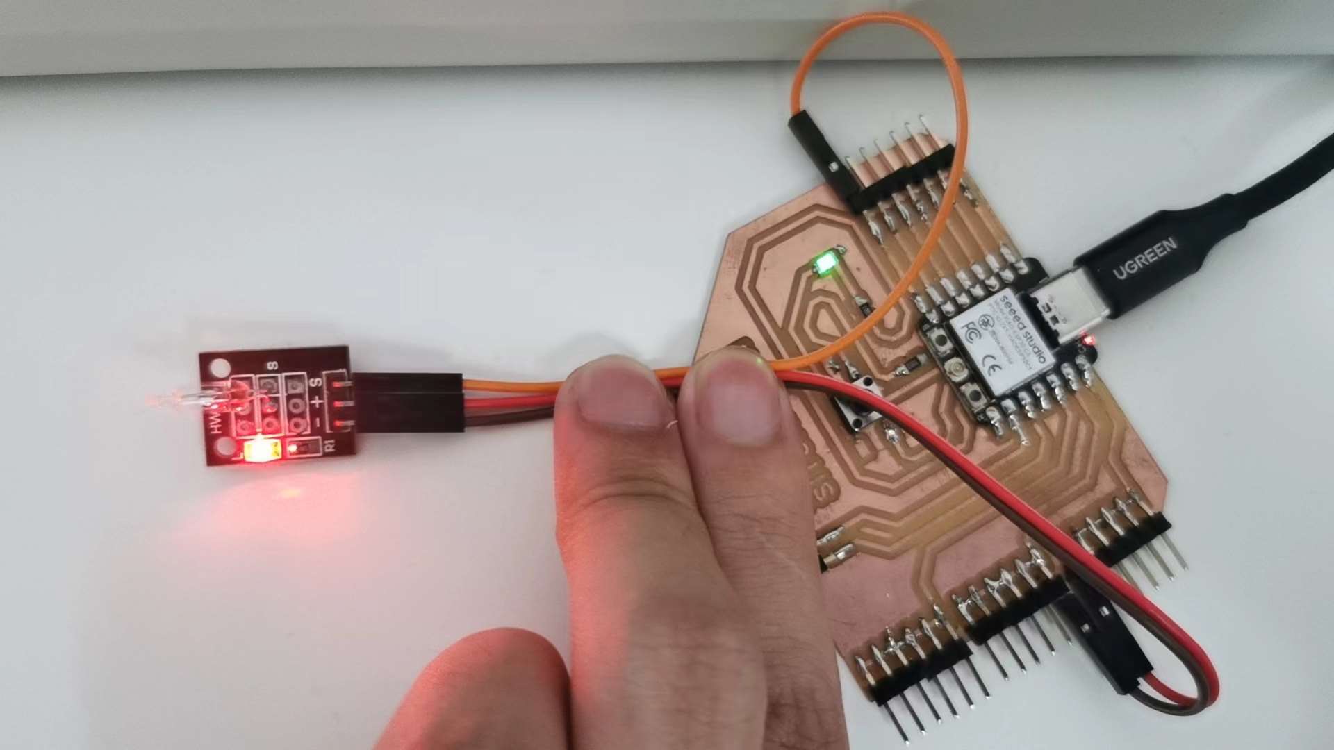
I programmed using Arduino IDE.
void setup() {
  // put your setup code here, to run once:
pinMode(9, INPUT);
Serial.begin(9600);
}

void loop() {
  // put your main code here, to run repeatedly:
int tilt = digitalRead(9);
Serial.println(tilt);
}
temperature sensor
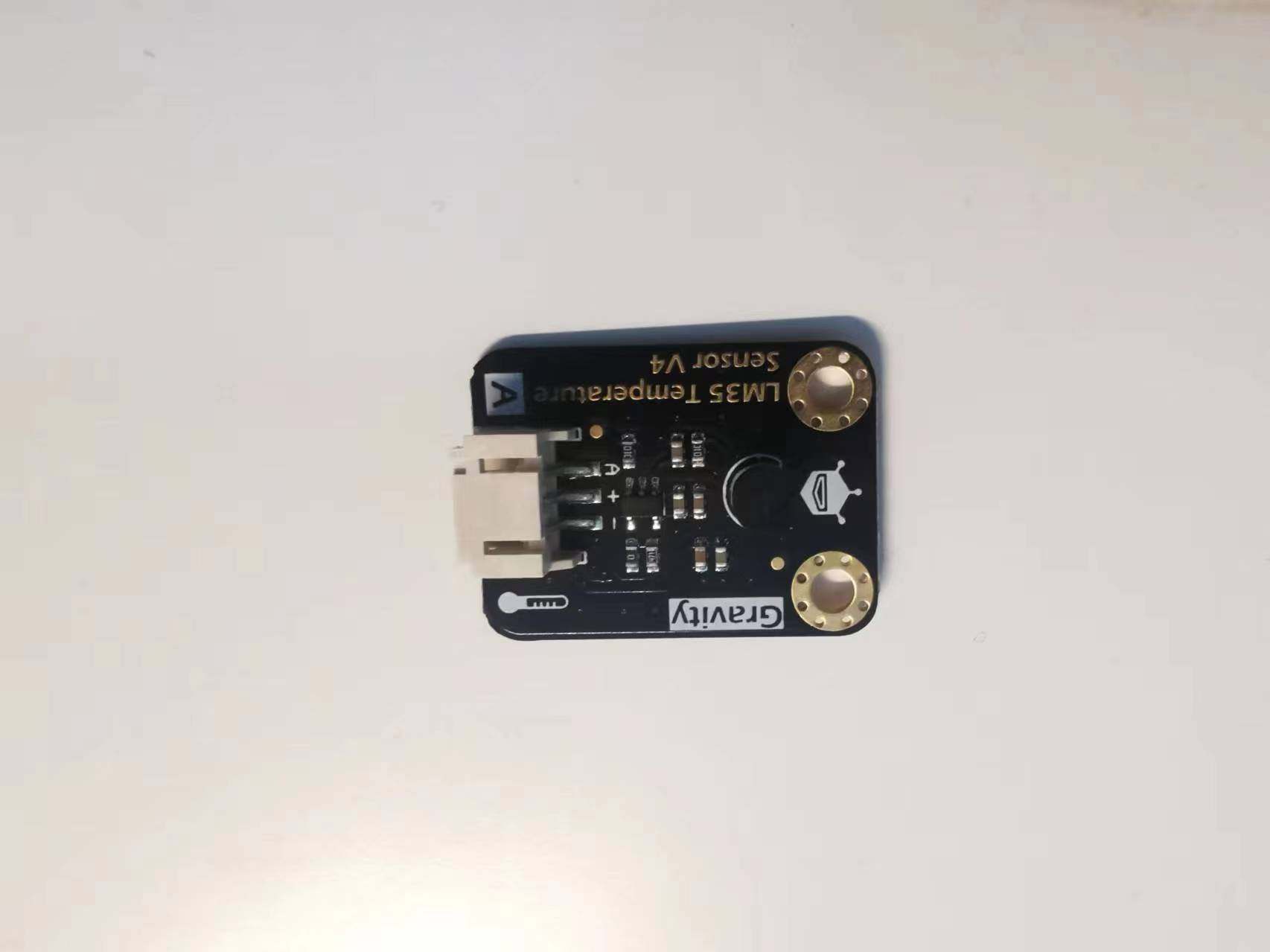
connected them to my board and programmed using Arduino IDE
void setup()
{
    Serial.begin(9600);//Set Baud Rate to 9600 bps
}


void loop()
{
    uint16_t val;
    double dat;
    val=analogRead(A0);//Connect LM35 on Analog 0
    dat = (double) val * (5.0/102.4);
    Serial.print("Tep:"); //Display the temperature on Serial monitor
    Serial.print(dat);
    Serial.println("C");
    delay(500);
}
sorce file:
temp.ino
tilt_sersor.ino