Week04-Electronics Production
Group assignment:
- Characterize the design rules for your in-house PCB production process: document feeds, speeds, plunge rate, depth of cut (traces and outline) and tooling.
- Document the workflow for sending a PCB to a board house
- Document your work to the group work page and reflect on your individual page what you learned
Individual assignment:
- Make and test a microcontroller development board
Checklist
- Linked to the group assignment page
- Documented how you made the toolpath
- Documented how you made (milled, stuffed, soldered) the board
- Documented that your board is functional
- Explained any problems and how you fixed them
- Uploaded your source code
- Included a ‘hero shot of your board
1. Group assignment:
- Model: Roland MDX-40A
- Software: Mods CE/Roland VPanel
- Tools: Milling bit 0,4 mm (1/64”); Milling bit 0,8 mm (1/32”)
- Material: FR-1 Printed Circuit Board 75 x 50 mm.
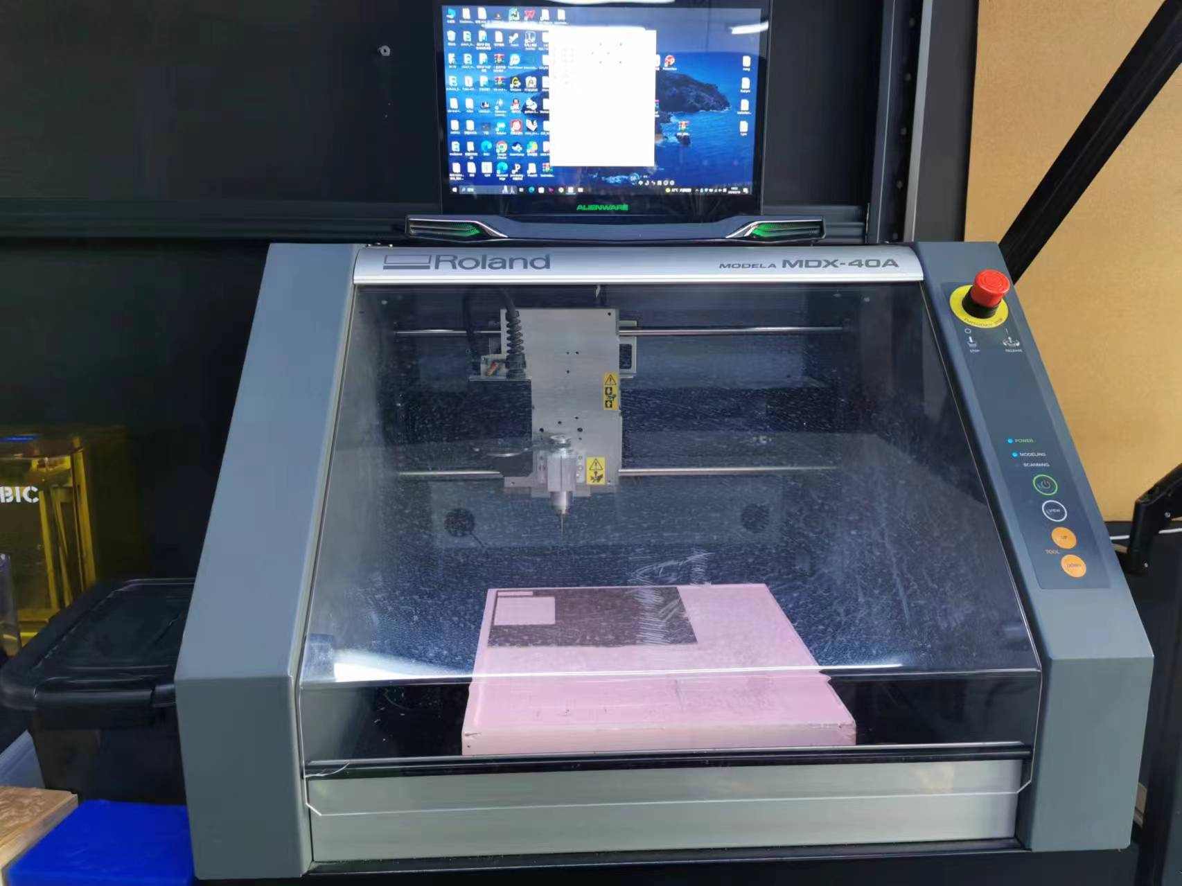
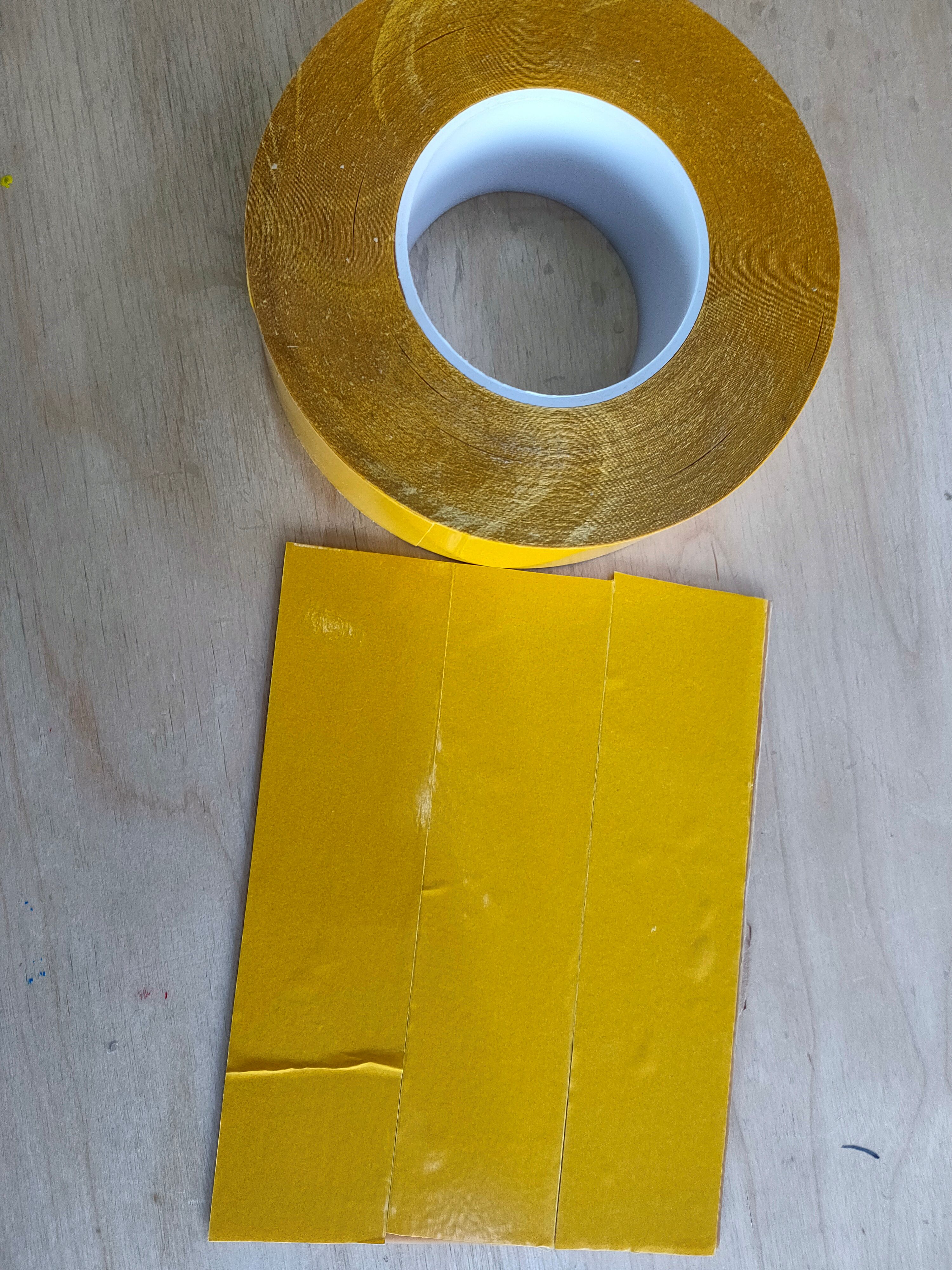
First, I placed the FR1 on the 410 MDF on the machine and secured it with double-sided tape.
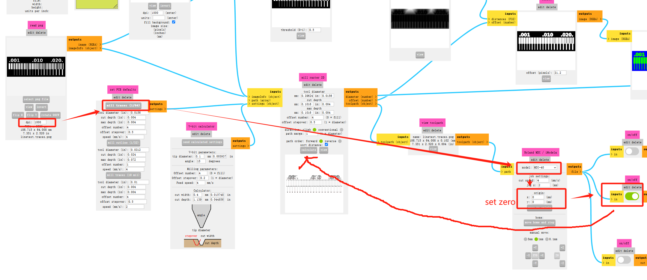
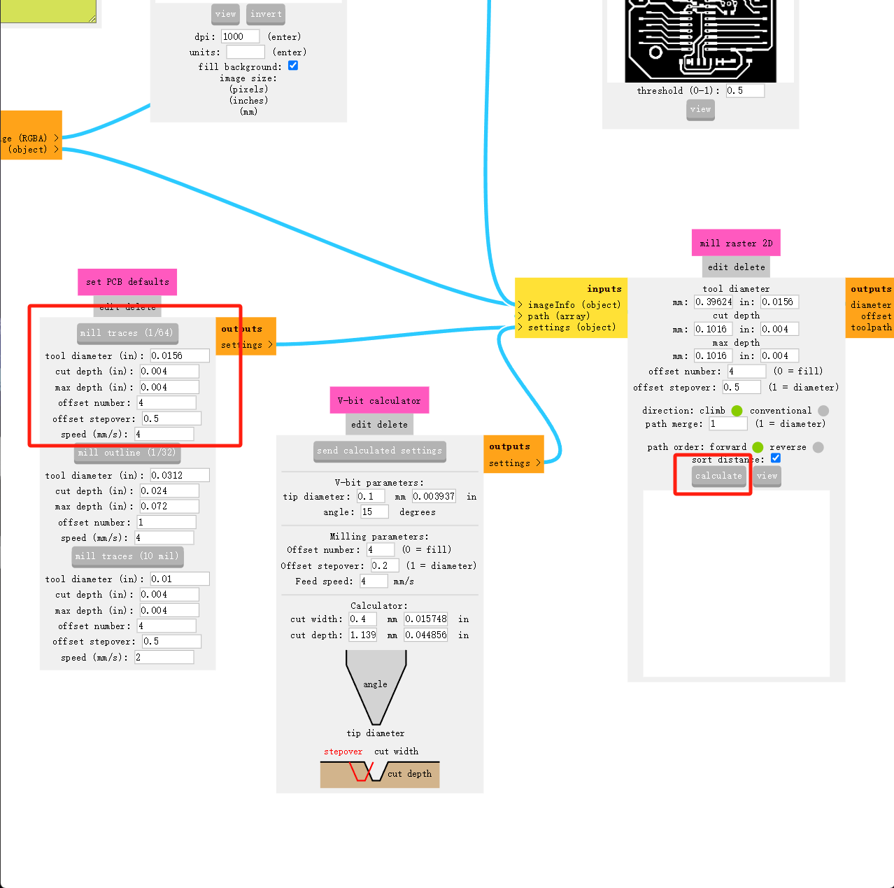
- Import the image from the official website into Mods, and modify the DPI to 1000; otherwise, the dimensions will be incorrect. After modification, you can verify the corresponding dimensions below.
- Choose the milling type, which corresponds to two types of end mills. Select “Set PCB defaults”:
- (1/64) is for circuit milling, with a cutting depth of 0.1.
- (1/32) is for through-hole milling, with a cutting depth of 1.8287. To avoid breaking the bit by cutting too deep at once, set the step-down depth to 0.6096 per cut.
- Note: The PNG file I uploaded has a white image with a black background. The toolpath will retain the white area and generate a cutting path around it.
- Select MDX-40, and adjust the origin to 0. Typically, we set the bottom as 0 for intuitive operation.
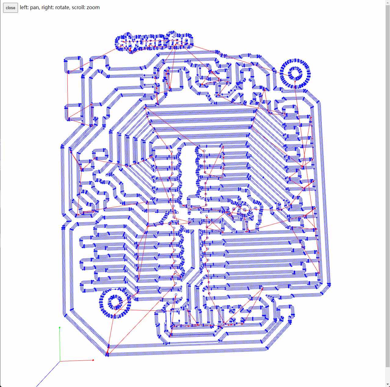
- Click Calculate to generate the toolpath. Make sure to check if it’s correct.
 Export the RML file using a USB drive; we need to transfer it to Roland VPanel! First, we need to change the bit, using a 0.4mm end mill here. Use a wrench to help, and remember the rule: tighten clockwise, loosen counterclockwise!
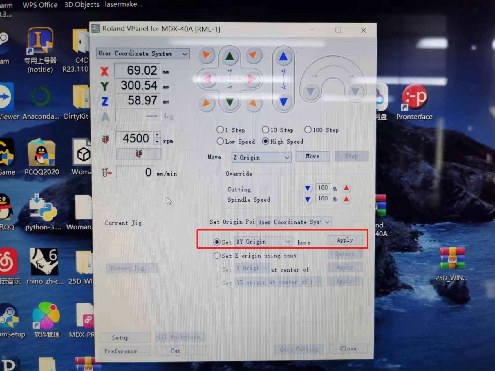
 Tool alignment: The origin of this machine is at the bottom-left corner. I move the toolhead to the bottom-left and click “Set XY” to set the origin.
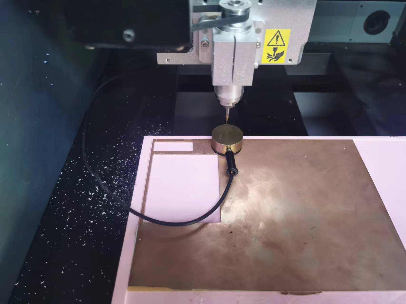
Using the automatic tool sensor, place it under the toolhead and clean the surface of the MDF and the sensor to avoid alignment errors. Click “Use sens-detect to set Z origin.”
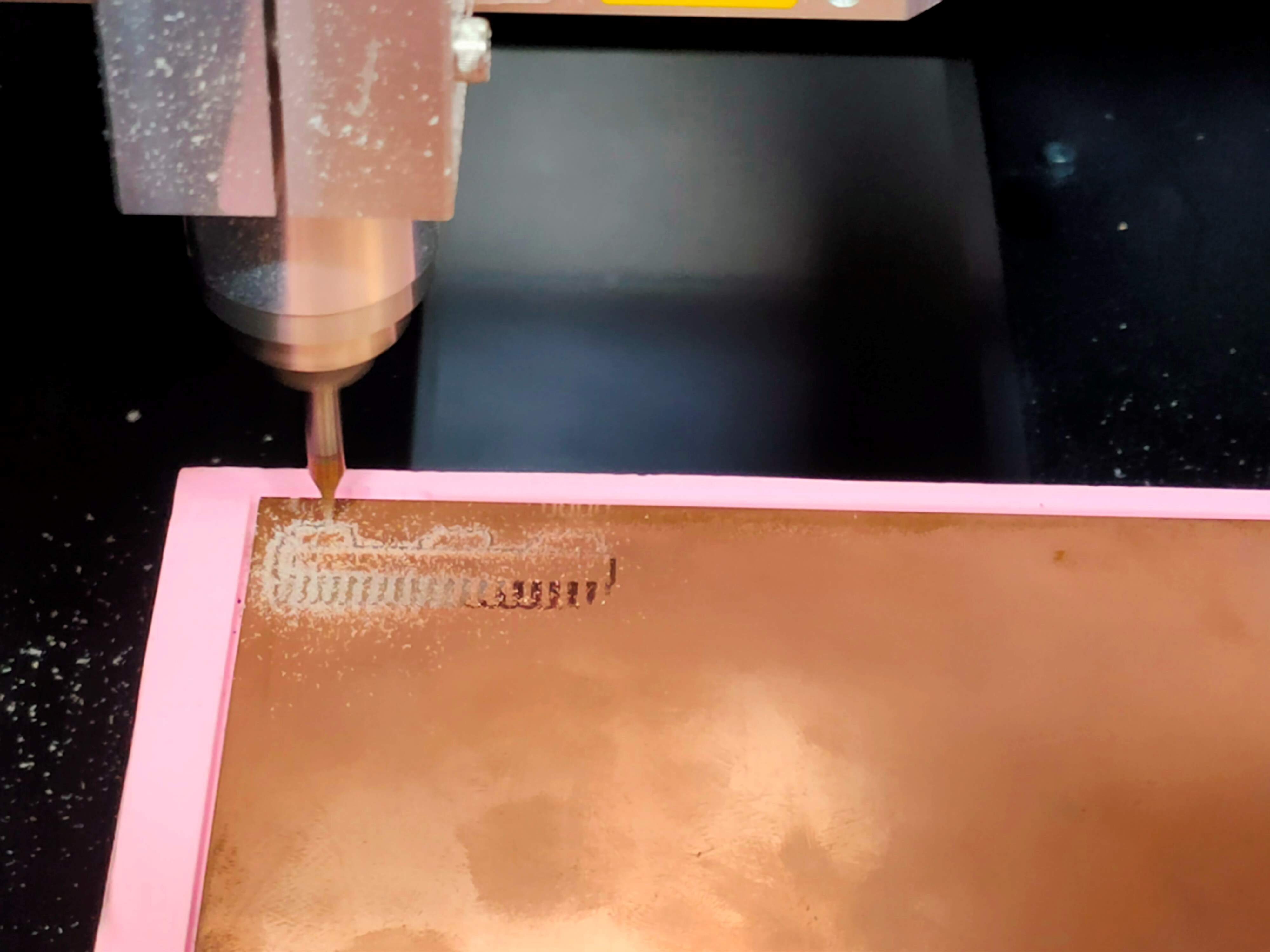
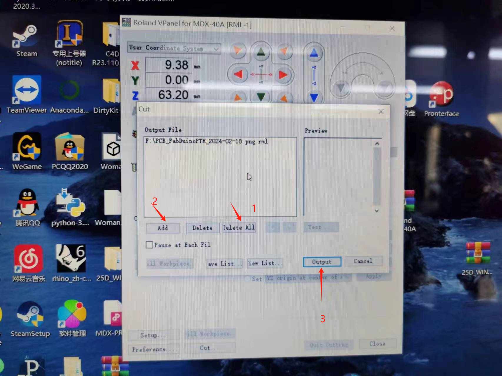
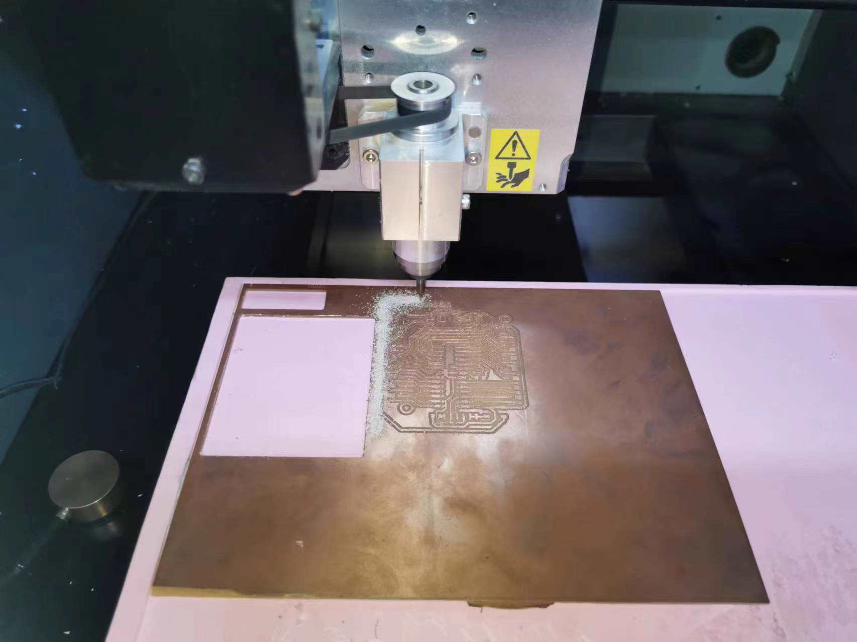
 We set the RPM to 5500, imported the file, and hit Output! The result… let’s just say it was less than ideal. After reviewing some records from past users, it seems our RPM was too low, which caused the issue…
We switched to a 0.8mm end mill to mill the outline and cut the piece out—to keep as a memento. Time to change the bit again…
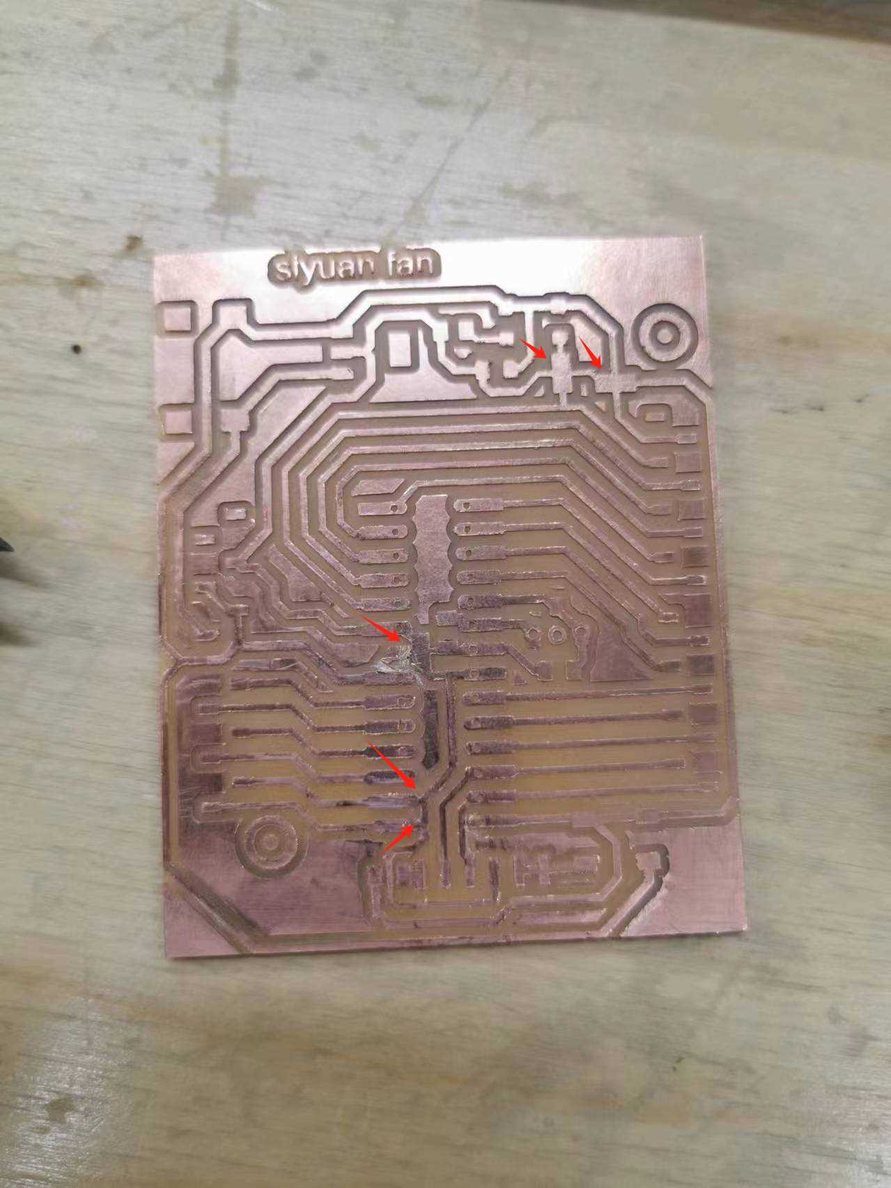
 Take a look at the results: the circuits from 001 to 006 are already damaged and look quite messy…
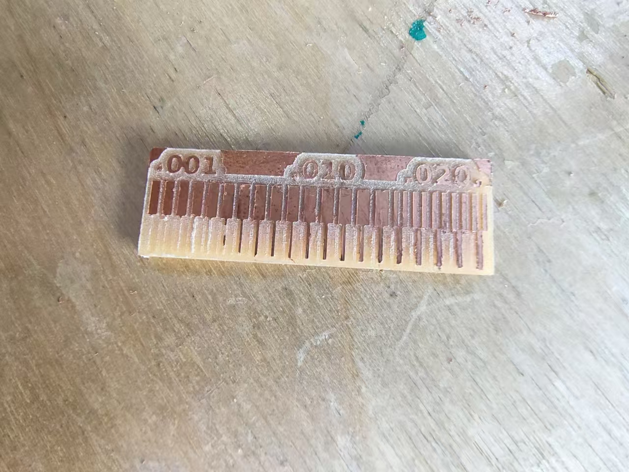 So, we adjusted the RPM to 11,000 and milled again. The steps had to be repeated because the previous milling used a 0.8mm bit. For each complete circuit board, we mill the traces first and then the outline to prevent the board from shifting.
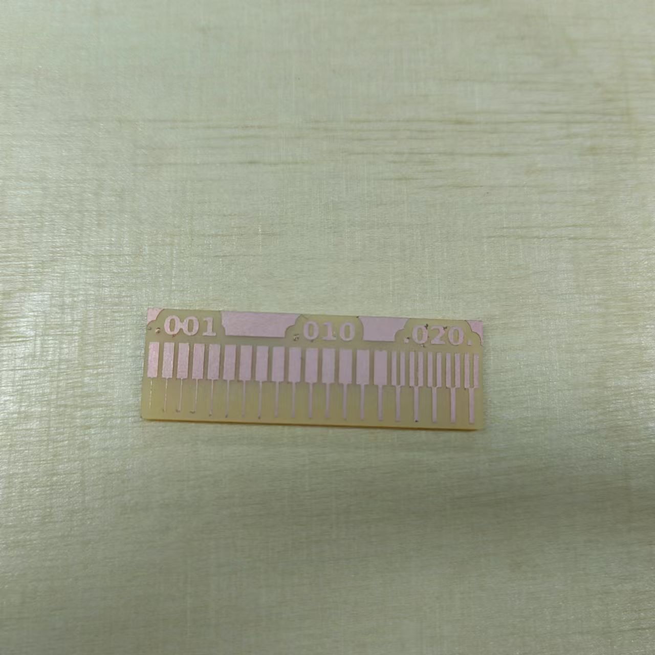
Below are the process and results of the second milling attempt:
What did I learn?
In this process, I learned how to properly set up and operate a CNC milling machine. First, ensure the material is securely fixed and choose the appropriate mill bit and cutting depth based on the task. When using the Mods software, it’s important to adjust the DPI and generate accurate toolpaths, while paying special attention to the machine’s tool offset and origin settings to ensure cutting precision. During the process, I realized the impact of RPM settings on the outcome. On my first attempt, the circuit was damaged due to a low RPM. After adjusting the RPM and optimizing the steps, I achieved the desired cutting result. This experience not only made me more familiar with CNC milling operations but also improved my problem-solving and process adjustment skills.
2. The machine and the PCB production process
The CNC model I used is as follows:
- Model: Roland MDX-40A
- Software: Mods CE/Roland VPanel
- Tools: Milling bit 0,4 mm (1/64”); Milling bit 0,8 mm (1/32”)
- Material: FR-1 Printed Circuit Board 75 x 50 mm.
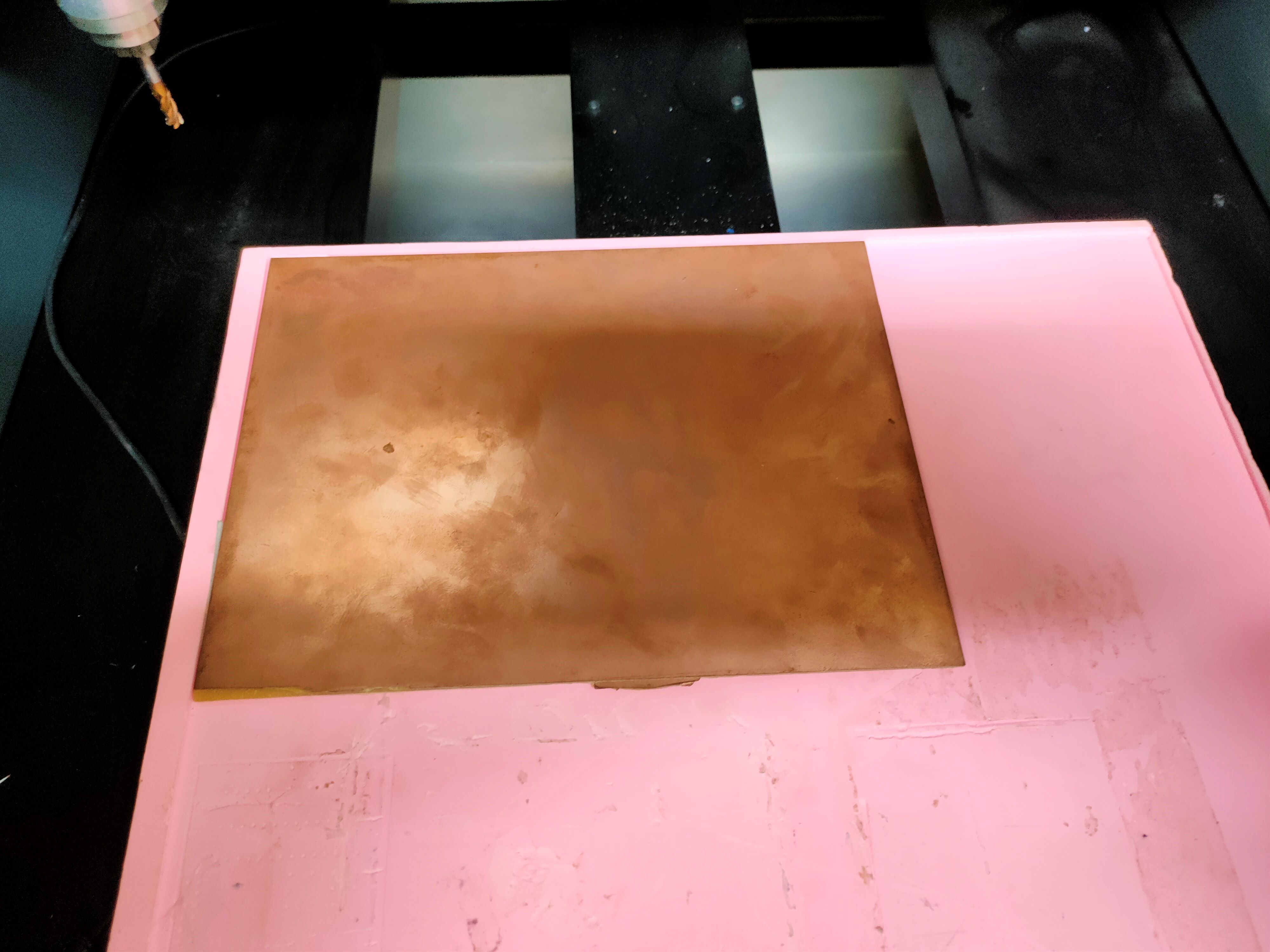
First, I applied double-sided tape to the back of the copper plate to prevent it from moving during cutting (which would make me cry). Then, I placed the copper plate on the pink unsaturated resin board on the machine.
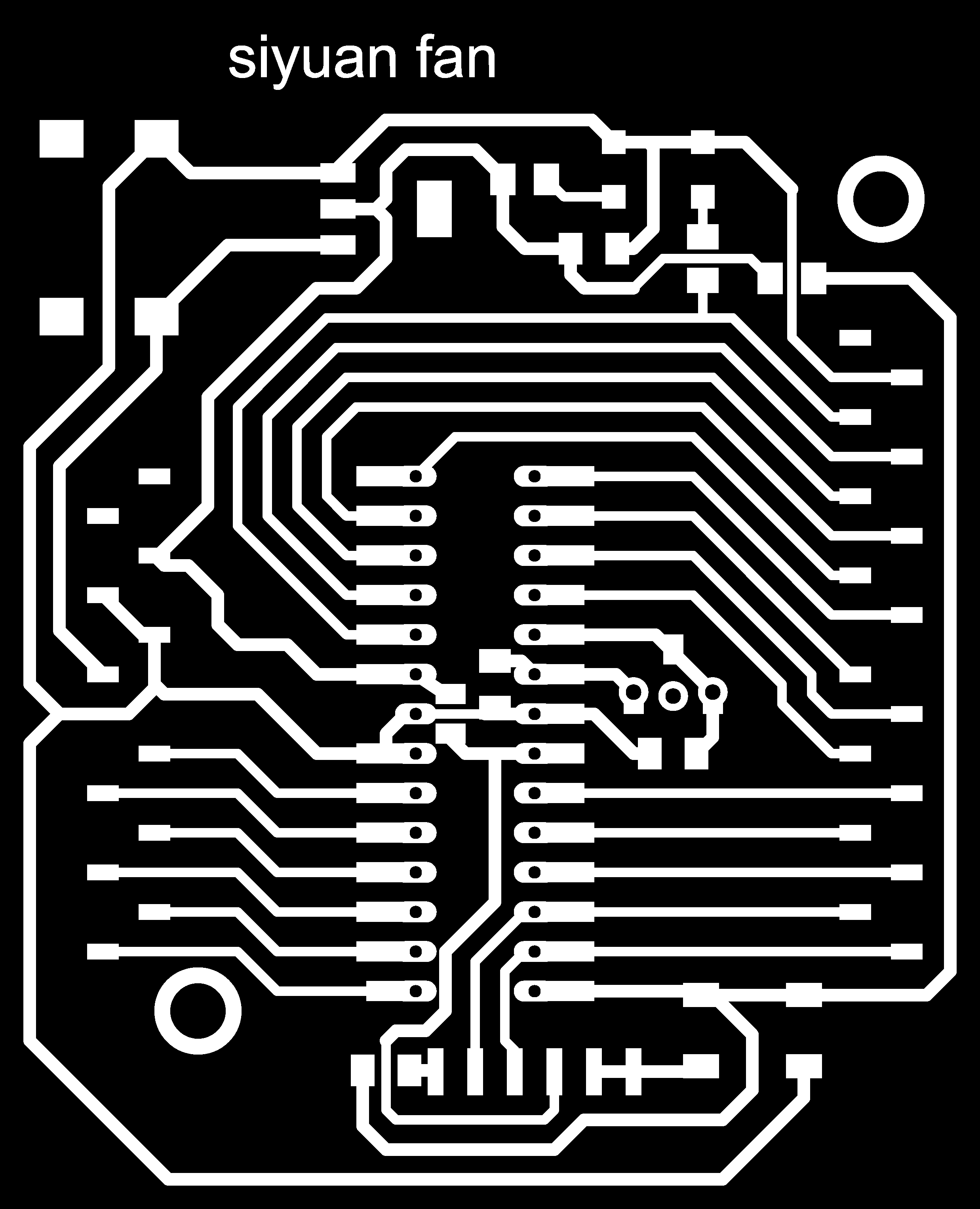
This week, I am going to make a development board with the main control chip as 328P. I found a related circuit diagram on Thingiverse, and I will use this circuit diagram for cutting.
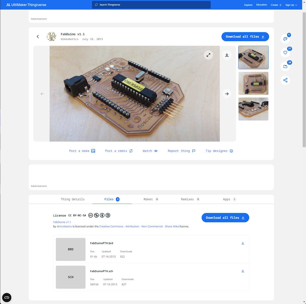
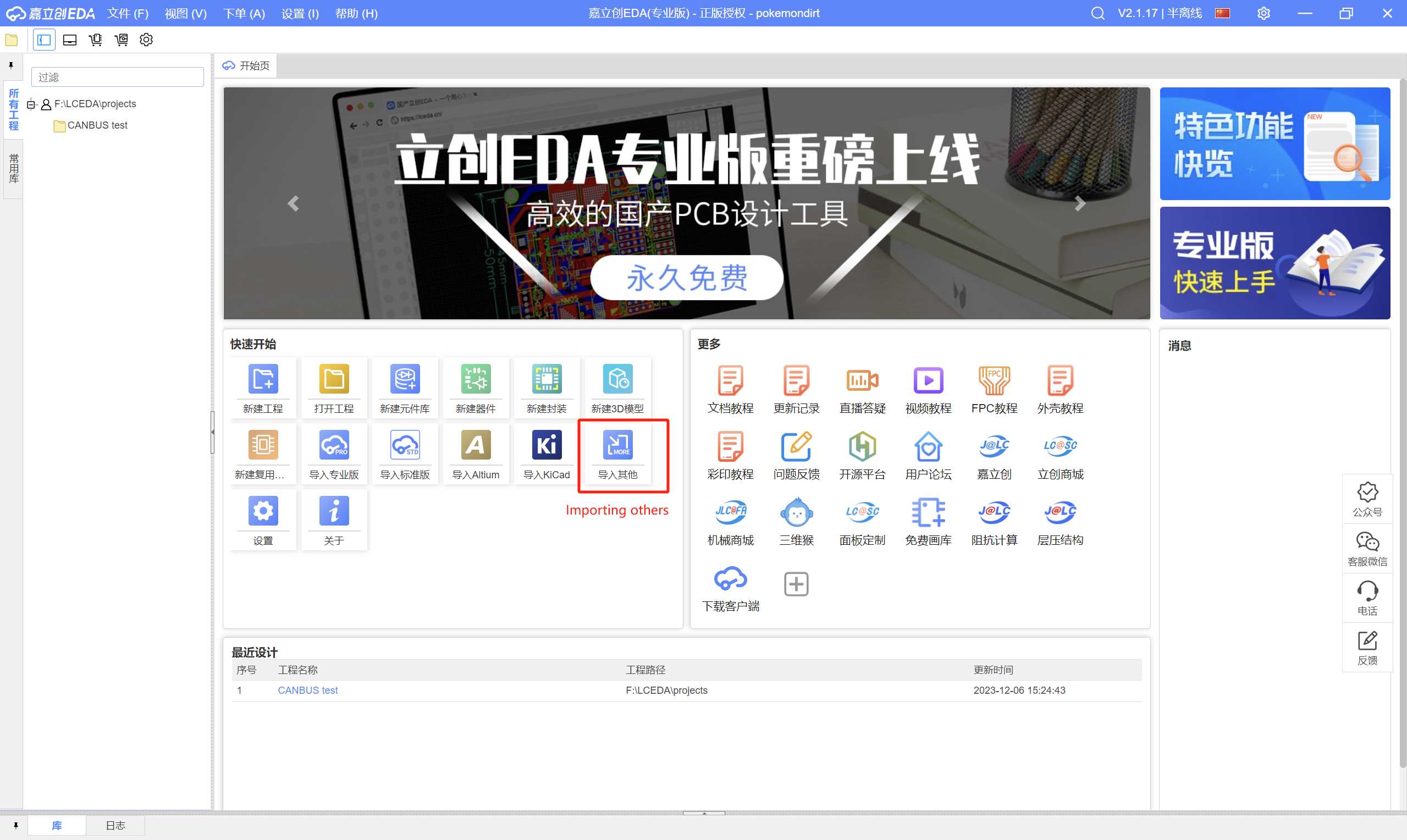
The first issue I encountered was that the files provided by the author were in .brd format, and I didn’t have that software on my computer. At this point, my friend suggested that I could use EasyEDA to import and view the files.

Select “Importing others” and import the necessary files.
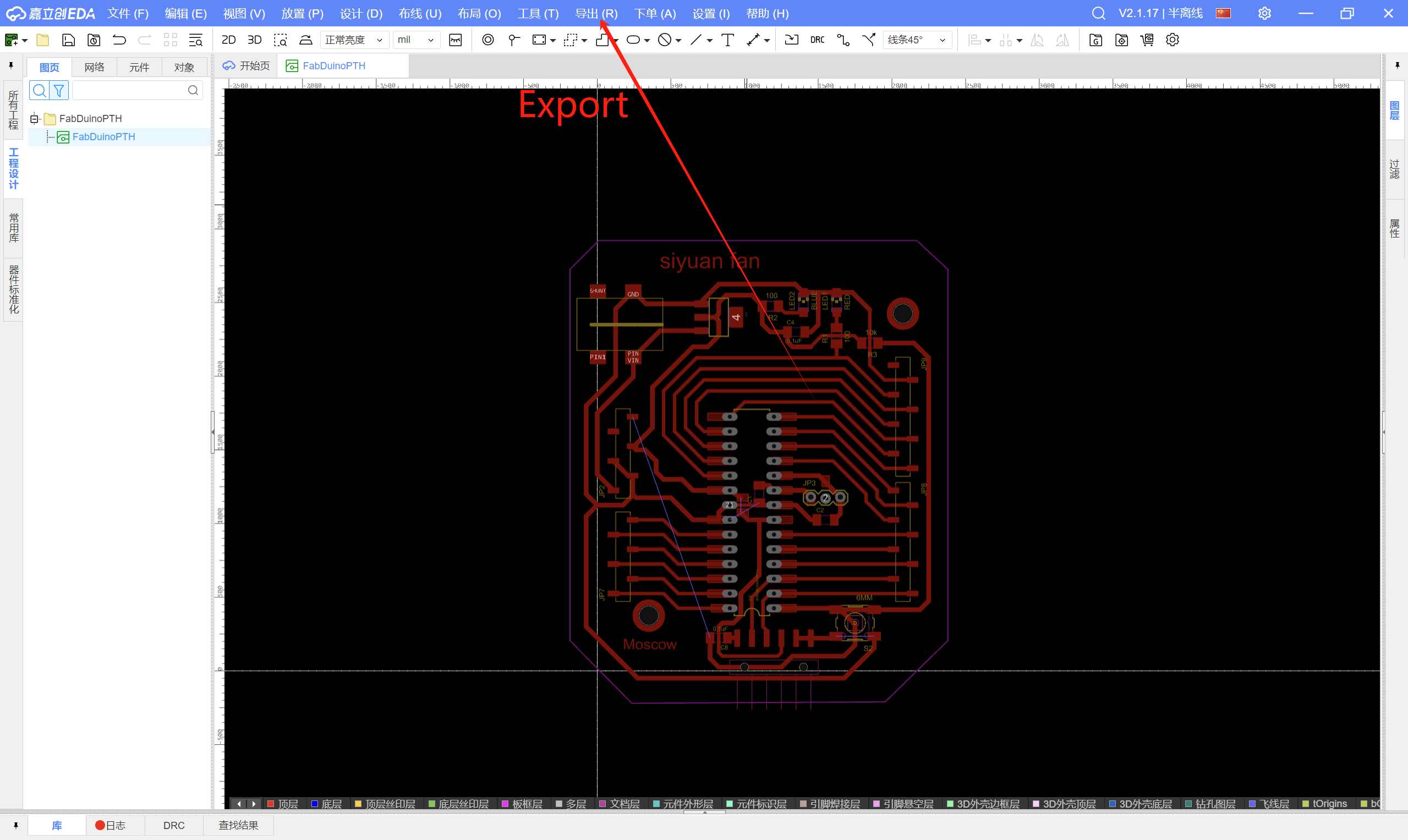
Select Export
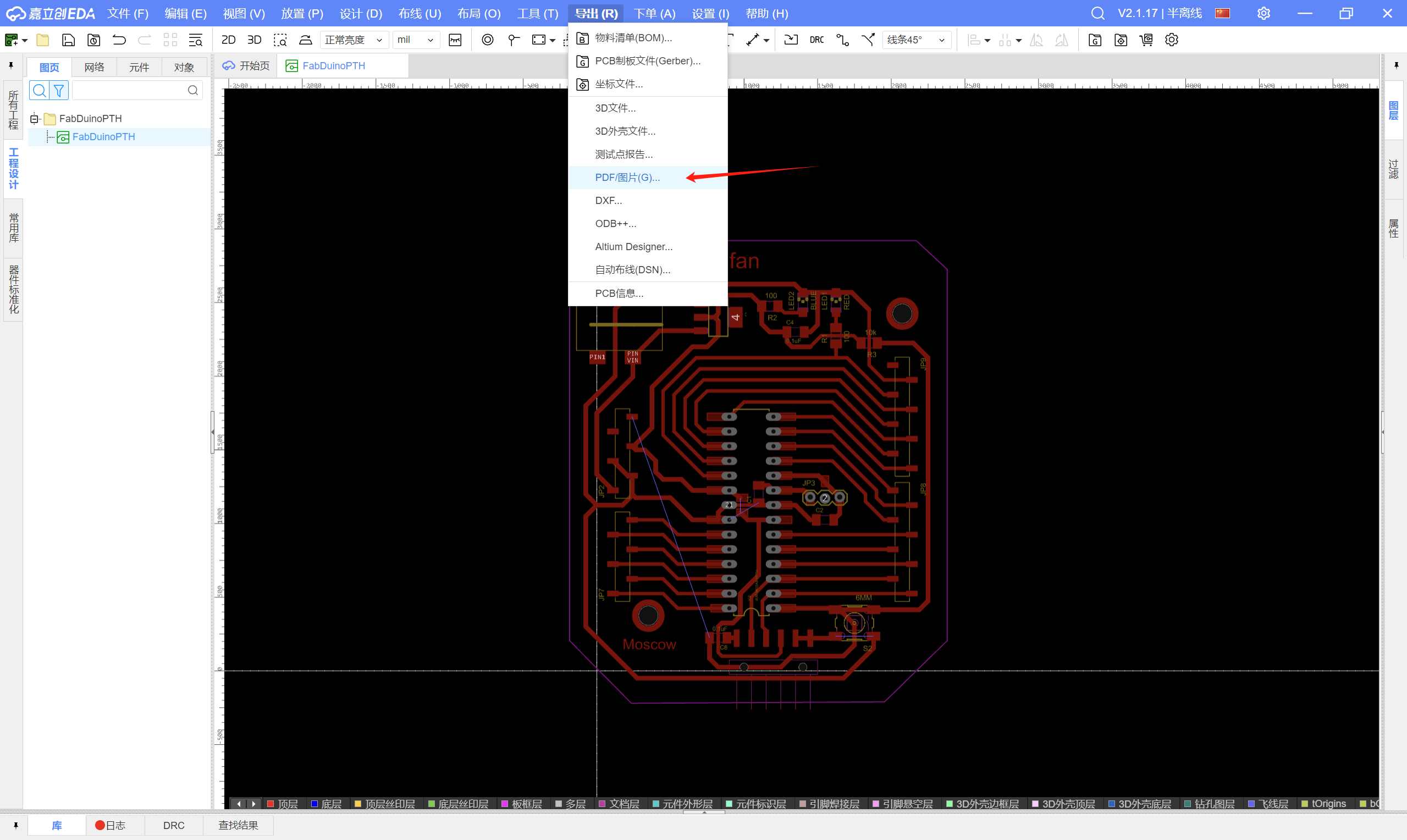
Select PDF
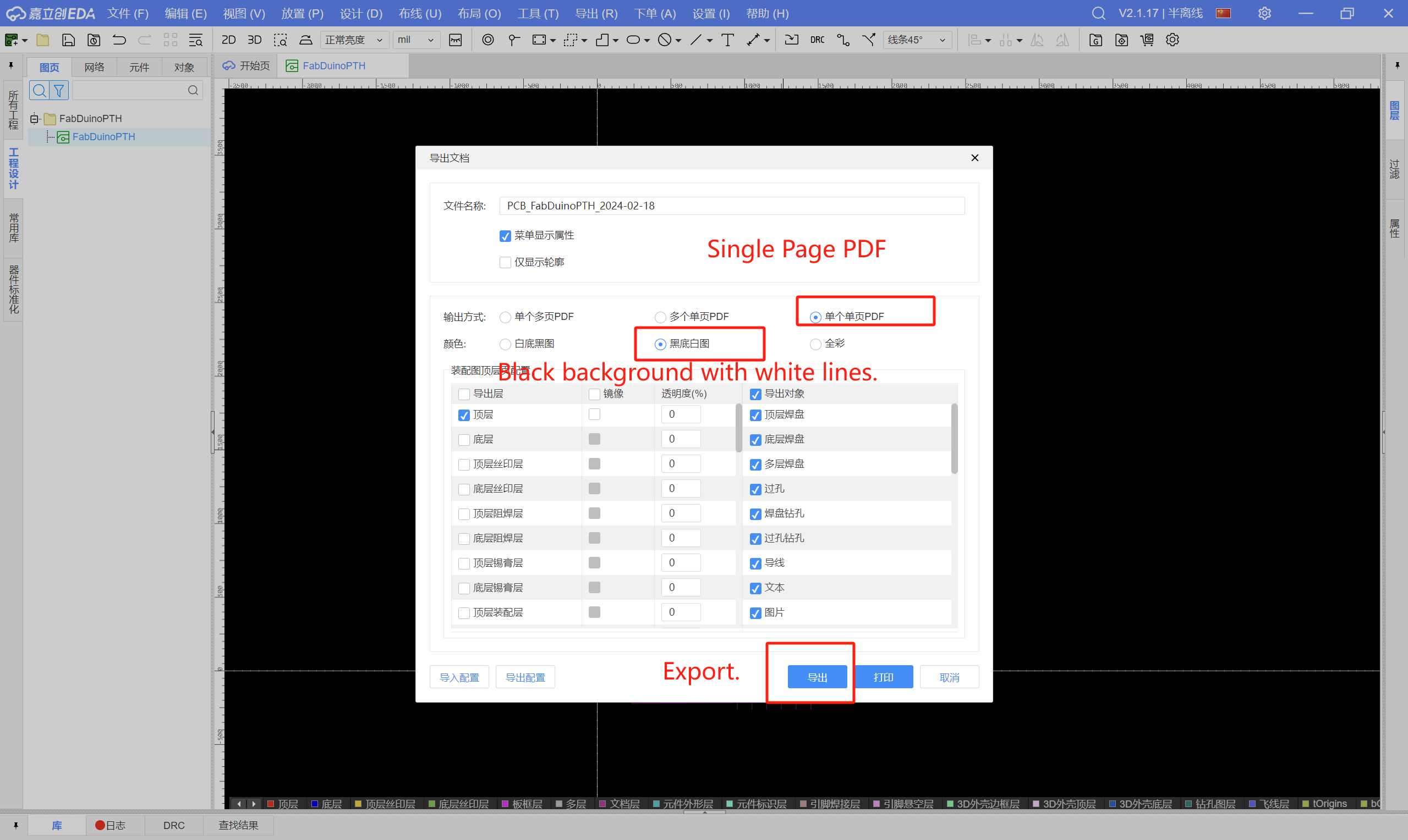
Select Single Page PDF > Black background with white lines > Export.
After exporting the PDF, I imported it into Photoshop because there was no border file.
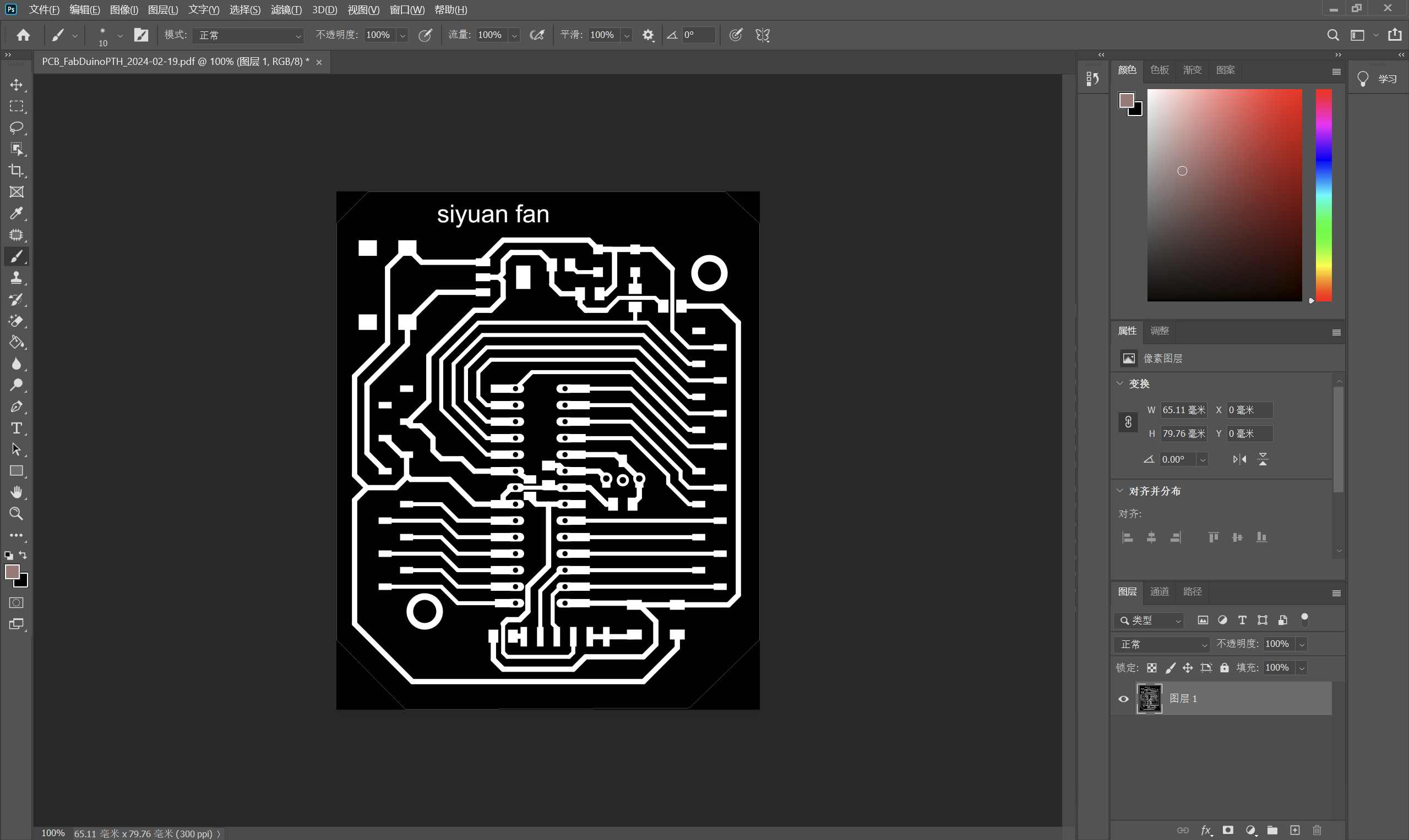
Add a new layer.
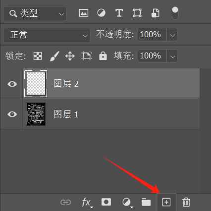
Use the paint bucket tool to fill the canvas with white color.

Select image > canvas size
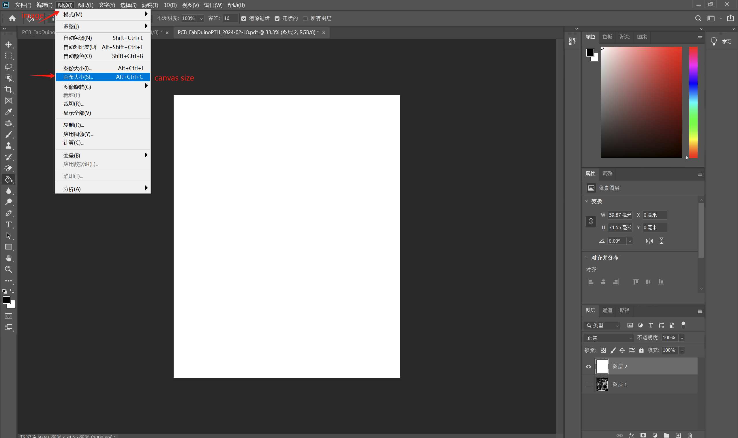
Increase by 3mm
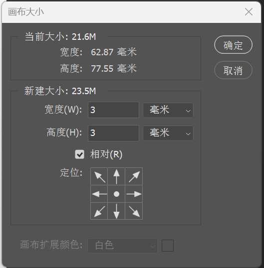
Fill the edges with black using the paint bucket tool, creating a border layer.

I used Mods CE to generate my G-code.
Open Mods CE, right-click, and select “Programs.”
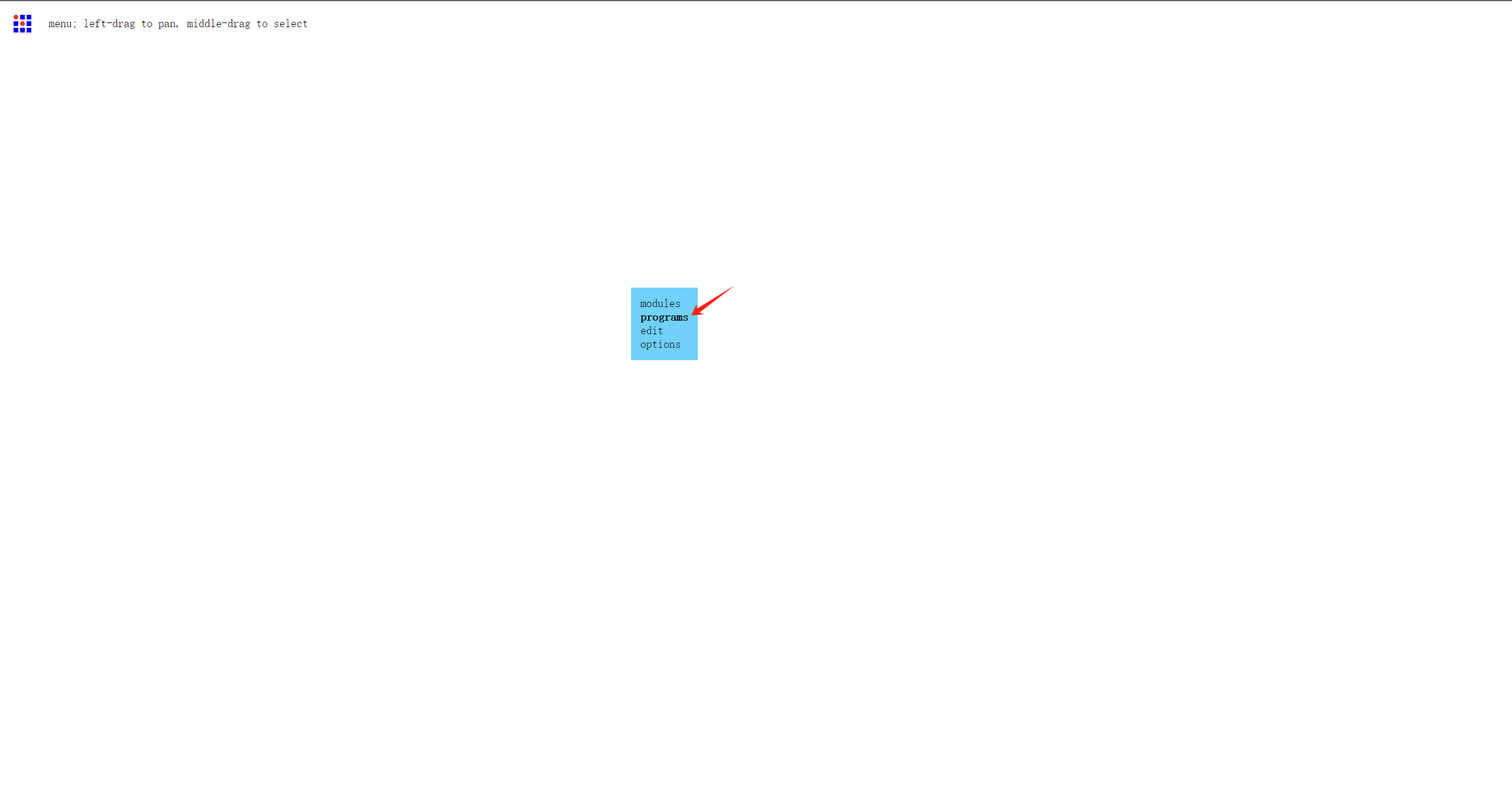
Select open program
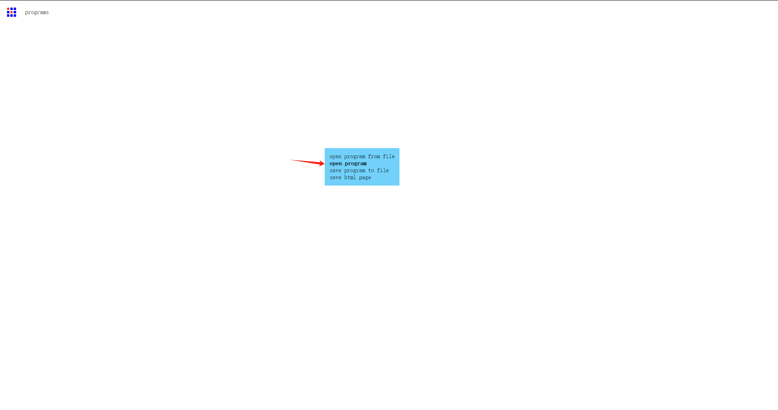
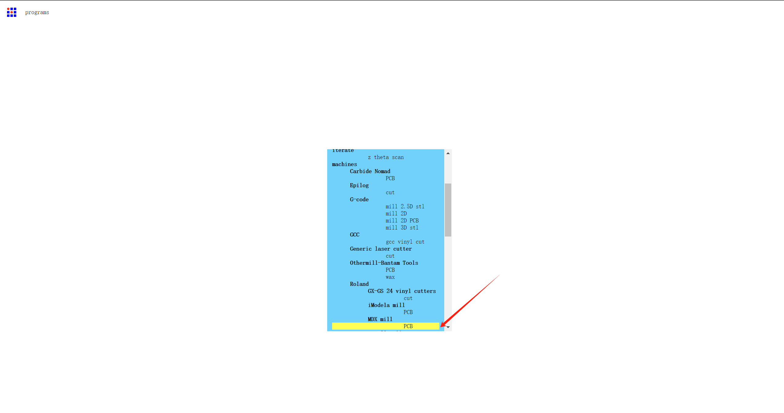
Select machines > Roland > MDX mill > PCB
select png file
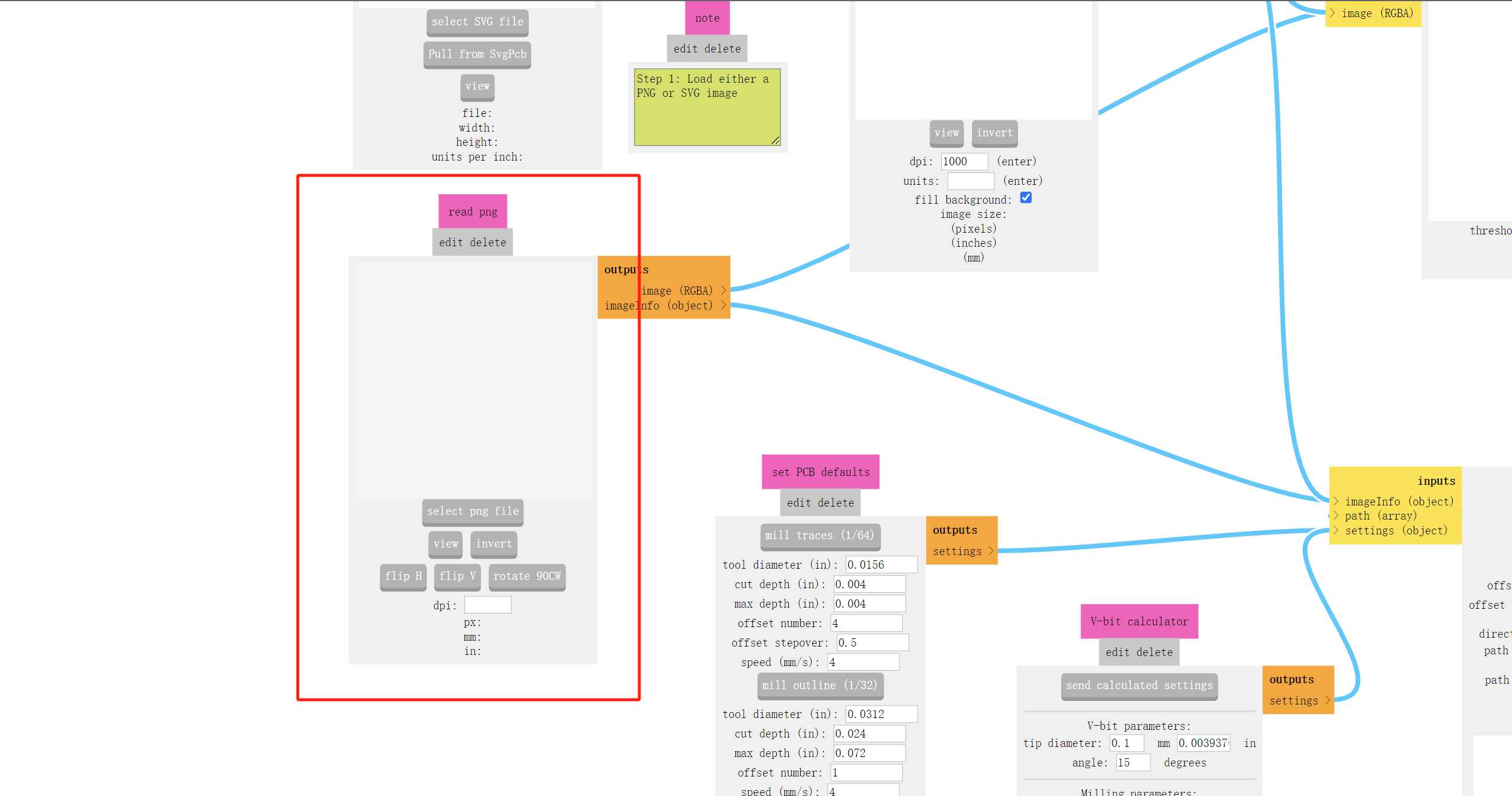
Select the machine model as “MDX-40” and set the origin to 0,0.
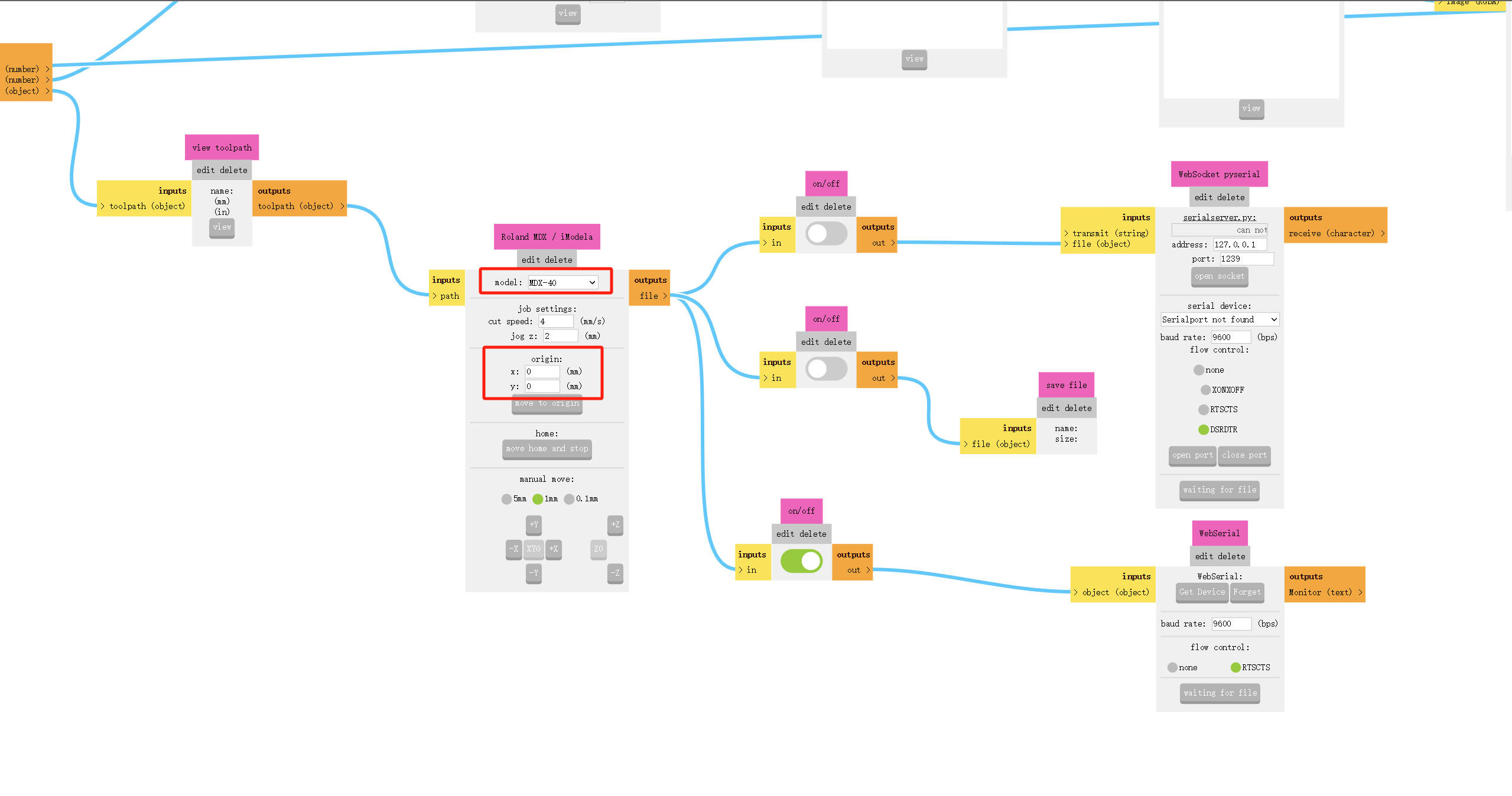
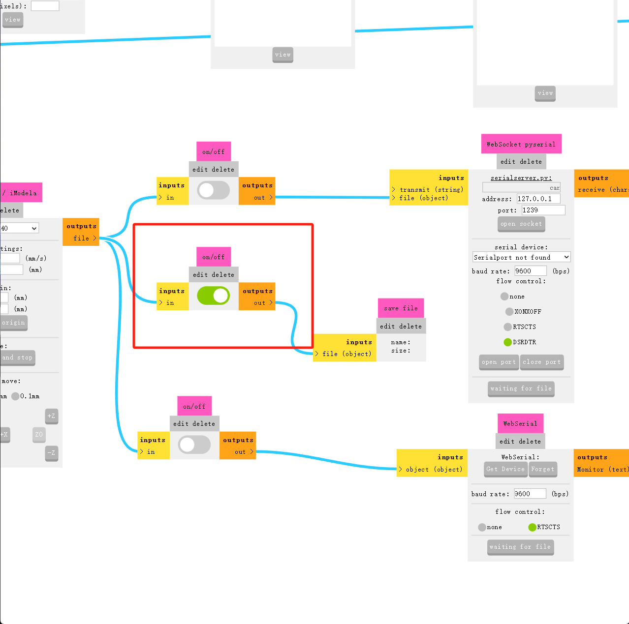
Open the “Save File” switch.
Choose 1/64, which is a 0.4mm cutter, and click “Calculate.”
The browser will automatically open a new tab, showing a preview of the cutter’s path. Congratulations to me for succeeding!🥳🥳🥳
Open the Roland VPanel software. The origin of this machine is in the lower-left corner. I moved the cutter head to the lower-left corner of the circuit board using the software and pressed “Set XY” to set it as the origin.
Here, I used an automatic tool setter, placing it beneath the drill bit. In the software, I clicked on “Set Z origin using sens-detect.”
I first deleted the files in the software because they were not mine. Then, I added the files generated earlier and clicked on “Output.”
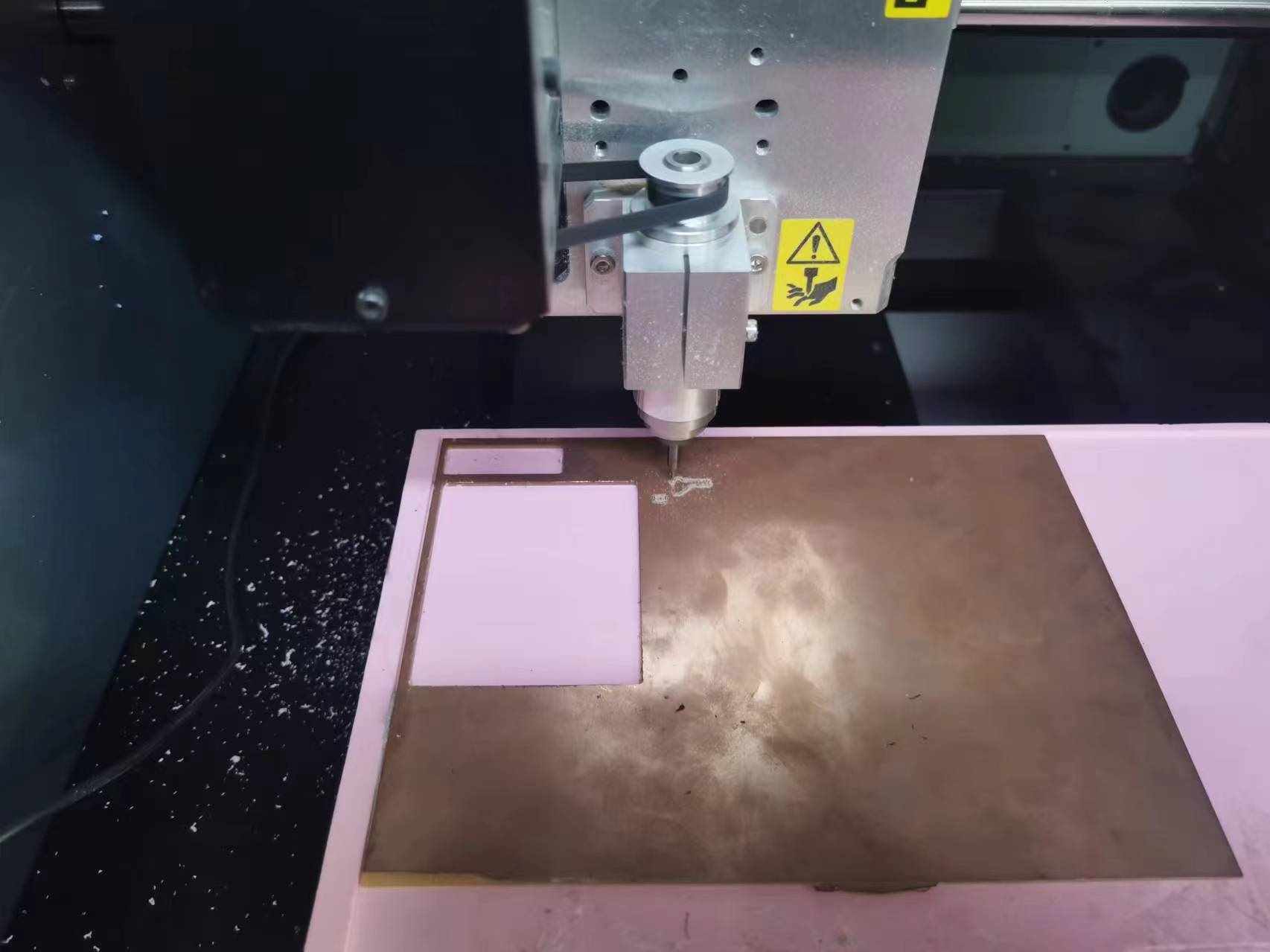
After a long wait, the machine began cutting the border.
Same as the previous steps, I selected 1/32 in Mods CE and clicked calculate.
 After using a vacuum cleaner to remove the dust, take out the circuit board.
3. test a microcontroller development board
First, I checked the circuit board and found several issues due to the gaps being too small for the tool to enter. This time, I manually cut them open with a utility knife.👇👇👇
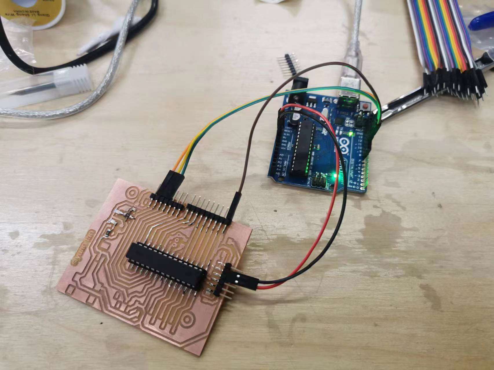
After cutting, I soldered the components onto the circuit board.
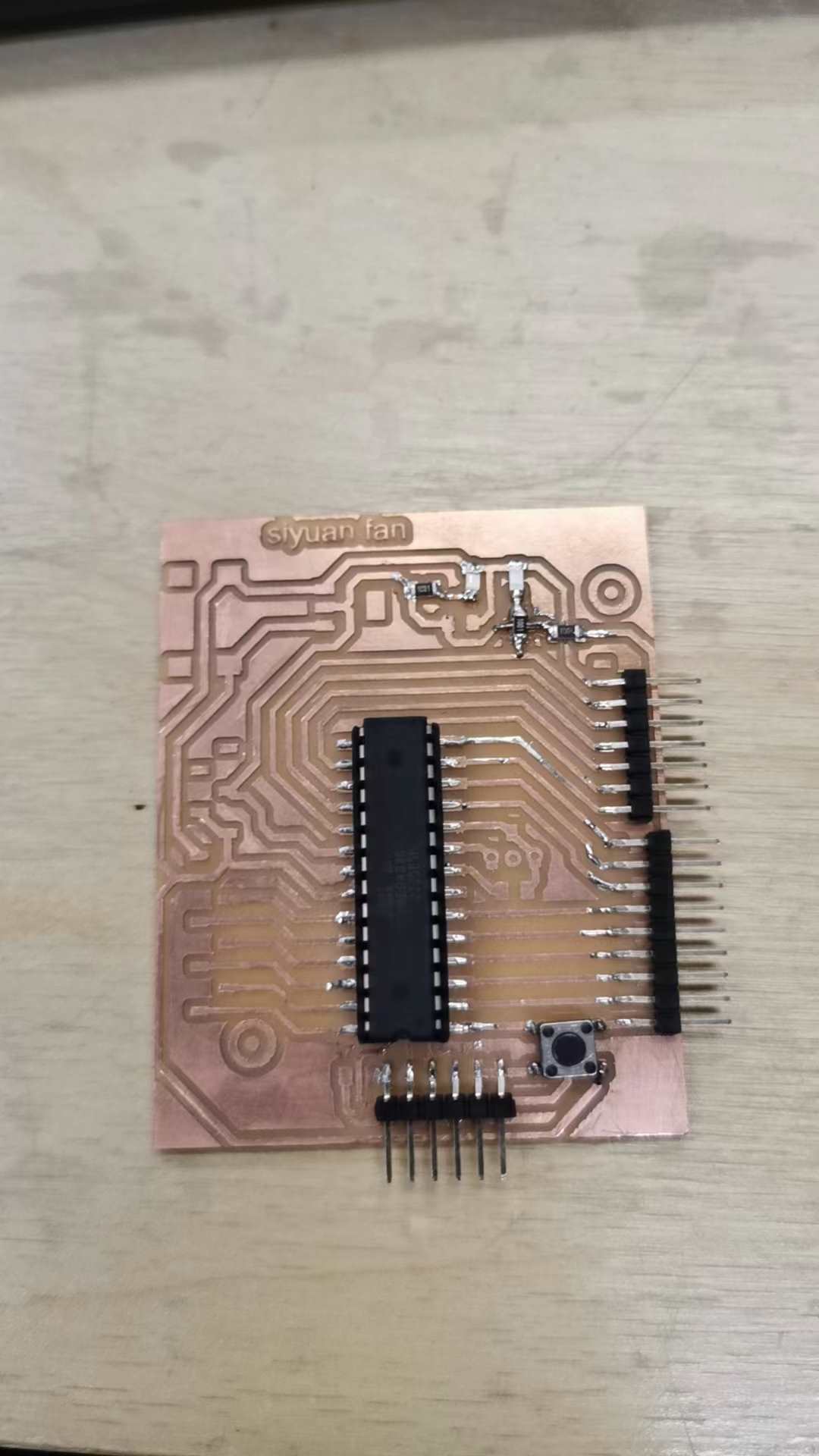
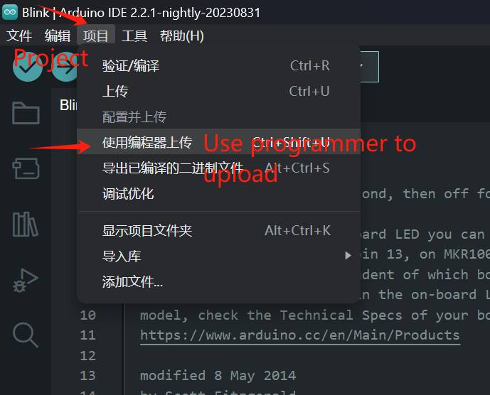
Because I used the 328P chip without a USB serial port, I will use the ISP protocol to program my development board through an Arduino Uno.
Reference documents:
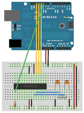
Because I don’t have an extra crystal oscillator, I configured the ATmega328P to use its internal 8 MHz RC oscillator as the clock source.Because I don’t have an extra crystal oscillator, I configured the ATmega328P to use its internal 8 MHz RC oscillator as the clock source.
I’ll need to install support for an additional hardware configuration:
- Download this hardware configuration archive: breadboard-1-6-x.zip
- Create a “hardware” sub-folder in your Arduino sketchbook folder (whose location you can find in the Arduino preferences dialog). If you’ve previously installed support for additional hardware configuration, you may already have a “hardware” folder in your sketchbook.
- Move the breadboard folder from the zip archive to the “hardware” folder of your Arduino sketchbook.
- Restart the Arduino software.
- You should see “ATmega328 on a breadboard (8 MHz internal clock)” in the Tools > Board menu.
connected to pins 10, 11, 12, and 13 of the Arduino board.
Open the IDE, and first, I will upload an ISP (In-System Programming) program to the UNO.
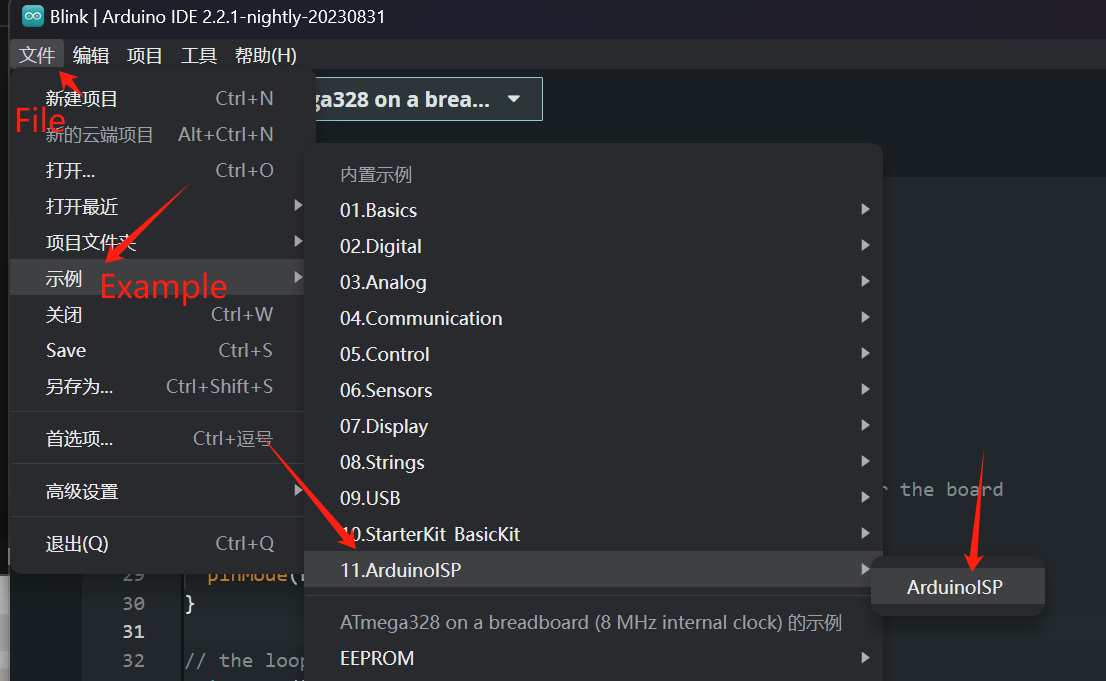
After uploading the program, create a new file. and Choose Blink from the example code.
It worked 🎉🎉🎉
“Here is my sorce file.”
“Here is my test code.”
Blink
void setup() {
  // initialize digital pin LED_BUILTIN as an output.
  pinMode(LED_BUILTIN, OUTPUT);
}

// the loop function runs over and over again forever
void loop() {
  digitalWrite(LED_BUILTIN, HIGH);  // turn the LED on (HIGH is the voltage level)
  delay(100);                      // wait for a second
  digitalWrite(LED_BUILTIN, LOW);   // turn the LED off by making the voltage LOW
  delay(100);                      // wait for a second
}
Arduino ISP
#include "Arduino.h"
#undef SERIAL


#define PROG_FLICKER true

// Configure SPI clock (in Hz).
// E.g. for an ATtiny @ 128 kHz: the datasheet states that both the high and low
// SPI clock pulse must be > 2 CPU cycles, so take 3 cycles i.e. divide target
// f_cpu by 6:
//     #define SPI_CLOCK            (128000/6)
//
// A clock slow enough for an ATtiny85 @ 1 MHz, is a reasonable default:

#define SPI_CLOCK (1000000 / 6)


// Select hardware or software SPI, depending on SPI clock.
// Currently only for AVR, for other architectures (Due, Zero,...), hardware SPI
// is probably too fast anyway.

#if defined(ARDUINO_ARCH_AVR)

#if SPI_CLOCK > (F_CPU / 128)
#define USE_HARDWARE_SPI
#endif

#endif

// Configure which pins to use:

// The standard pin configuration.
#ifndef ARDUINO_HOODLOADER2

#define RESET 10  // Use pin 10 to reset the target rather than SS
#define LED_HB 9
#define LED_ERR 8
#define LED_PMODE 7

// Uncomment following line to use the old Uno style wiring
// (using pin 11, 12 and 13 instead of the SPI header) on Leonardo, Due...

// #define USE_OLD_STYLE_WIRING

#ifdef USE_OLD_STYLE_WIRING

#define PIN_MOSI 11
#define PIN_MISO 12
#define PIN_SCK 13

#endif

// HOODLOADER2 means running sketches on the ATmega16U2 serial converter chips
// on Uno or Mega boards. We must use pins that are broken out:
#else

#define RESET 4
#define LED_HB 7
#define LED_ERR 6
#define LED_PMODE 5

#endif

// By default, use hardware SPI pins:
#ifndef PIN_MOSI
#define PIN_MOSI MOSI
#endif

#ifndef PIN_MISO
#define PIN_MISO MISO
#endif

#ifndef PIN_SCK
#define PIN_SCK SCK
#endif

// Force bitbanged SPI if not using the hardware SPI pins:
#if (PIN_MISO != MISO) || (PIN_MOSI != MOSI) || (PIN_SCK != SCK)
#undef USE_HARDWARE_SPI
#endif


// Configure the serial port to use.
//
// Prefer the USB virtual serial port (aka. native USB port), if the Arduino has one:
//   - it does not autoreset (except for the magic baud rate of 1200).
//   - it is more reliable because of USB handshaking.
//
// Leonardo and similar have an USB virtual serial port: 'Serial'.
// Due and Zero have an USB virtual serial port: 'SerialUSB'.
//
// On the Due and Zero, 'Serial' can be used too, provided you disable autoreset.
// To use 'Serial': #define SERIAL Serial

#ifdef SERIAL_PORT_USBVIRTUAL
#define SERIAL SERIAL_PORT_USBVIRTUAL
#else
#define SERIAL Serial
#endif


// Configure the baud rate:

#define BAUDRATE 19200
// #define BAUDRATE	115200
// #define BAUDRATE	1000000


#define HWVER 2
#define SWMAJ 1
#define SWMIN 18

// STK Definitions
#define STK_OK 0x10
#define STK_FAILED 0x11
#define STK_UNKNOWN 0x12
#define STK_INSYNC 0x14
#define STK_NOSYNC 0x15
#define CRC_EOP 0x20  //ok it is a space...

void pulse(int pin, int times);

#ifdef USE_HARDWARE_SPI
#include "SPI.h"
#else

#define SPI_MODE0 0x00

#if !defined(ARDUINO_API_VERSION) || ARDUINO_API_VERSION != 10001  // A SPISettings class is declared by ArduinoCore-API 1.0.1
class SPISettings {
public:
  // clock is in Hz
  SPISettings(uint32_t clock, uint8_t bitOrder, uint8_t dataMode)
    : clockFreq(clock) {
    (void)bitOrder;
    (void)dataMode;
  };

  uint32_t getClockFreq() const {
    return clockFreq;
  }

private:
  uint32_t clockFreq;
};
#endif                                                             // !defined(ARDUINO_API_VERSION)

class BitBangedSPI {
public:
  void begin() {
    digitalWrite(PIN_SCK, LOW);
    digitalWrite(PIN_MOSI, LOW);
    pinMode(PIN_SCK, OUTPUT);
    pinMode(PIN_MOSI, OUTPUT);
    pinMode(PIN_MISO, INPUT);
  }

  void beginTransaction(SPISettings settings) {
    pulseWidth = (500000 + settings.getClockFreq() - 1) / settings.getClockFreq();
    if (pulseWidth == 0) {
      pulseWidth = 1;
    }
  }

  void end() {}

  uint8_t transfer(uint8_t b) {
    for (unsigned int i = 0; i < 8; ++i) {
      digitalWrite(PIN_MOSI, (b & 0x80) ? HIGH : LOW);
      digitalWrite(PIN_SCK, HIGH);
      delayMicroseconds(pulseWidth);
      b = (b << 1) | digitalRead(PIN_MISO);
      digitalWrite(PIN_SCK, LOW);  // slow pulse
      delayMicroseconds(pulseWidth);
    }
    return b;
  }

private:
  unsigned long pulseWidth;  // in microseconds
};

static BitBangedSPI SPI;

#endif

void setup() {
  SERIAL.begin(BAUDRATE);

  pinMode(LED_PMODE, OUTPUT);
  pulse(LED_PMODE, 2);
  pinMode(LED_ERR, OUTPUT);
  pulse(LED_ERR, 2);
  pinMode(LED_HB, OUTPUT);
  pulse(LED_HB, 2);
}

int ISPError = 0;
int pmode = 0;
// address for reading and writing, set by 'U' command
unsigned int here;
uint8_t buff[256];  // global block storage

#define beget16(addr) (*addr * 256 + *(addr + 1))
typedef struct param {
  uint8_t devicecode;
  uint8_t revision;
  uint8_t progtype;
  uint8_t parmode;
  uint8_t polling;
  uint8_t selftimed;
  uint8_t lockbytes;
  uint8_t fusebytes;
  uint8_t flashpoll;
  uint16_t eeprompoll;
  uint16_t pagesize;
  uint16_t eepromsize;
  uint32_t flashsize;
} parameter;

parameter param;

// this provides a heartbeat on pin 9, so you can tell the software is running.
uint8_t hbval = 128;
int8_t hbdelta = 8;
void heartbeat() {
  static unsigned long last_time = 0;
  unsigned long now = millis();
  if ((now - last_time) < 40) {
    return;
  }
  last_time = now;
  if (hbval > 192) {
    hbdelta = -hbdelta;
  }
  if (hbval < 32) {
    hbdelta = -hbdelta;
  }
  hbval += hbdelta;
  analogWrite(LED_HB, hbval);
}

static bool rst_active_high;

void reset_target(bool reset) {
  digitalWrite(RESET, ((reset && rst_active_high) || (!reset && !rst_active_high)) ? HIGH : LOW);
}

void loop(void) {
  // is pmode active?
  if (pmode) {
    digitalWrite(LED_PMODE, HIGH);
  } else {
    digitalWrite(LED_PMODE, LOW);
  }
  // is there an error?
  if (ISPError) {
    digitalWrite(LED_ERR, HIGH);
  } else {
    digitalWrite(LED_ERR, LOW);
  }

  // light the heartbeat LED
  heartbeat();
  if (SERIAL.available()) {
    avrisp();
  }
}

uint8_t getch() {
  while (!SERIAL.available())
    ;
  return SERIAL.read();
}
void fill(int n) {
  for (int x = 0; x < n; x++) {
    buff[x] = getch();
  }
}

#define PTIME 30
void pulse(int pin, int times) {
  do {
    digitalWrite(pin, HIGH);
    delay(PTIME);
    digitalWrite(pin, LOW);
    delay(PTIME);
  } while (times--);
}

void prog_lamp(int state) {
  if (PROG_FLICKER) {
    digitalWrite(LED_PMODE, state);
  }
}

uint8_t spi_transaction(uint8_t a, uint8_t b, uint8_t c, uint8_t d) {
  SPI.transfer(a);
  SPI.transfer(b);
  SPI.transfer(c);
  return SPI.transfer(d);
}

void empty_reply() {
  if (CRC_EOP == getch()) {
    SERIAL.print((char)STK_INSYNC);
    SERIAL.print((char)STK_OK);
  } else {
    ISPError++;
    SERIAL.print((char)STK_NOSYNC);
  }
}

void breply(uint8_t b) {
  if (CRC_EOP == getch()) {
    SERIAL.print((char)STK_INSYNC);
    SERIAL.print((char)b);
    SERIAL.print((char)STK_OK);
  } else {
    ISPError++;
    SERIAL.print((char)STK_NOSYNC);
  }
}

void get_version(uint8_t c) {
  switch (c) {
    case 0x80:
      breply(HWVER);
      break;
    case 0x81:
      breply(SWMAJ);
      break;
    case 0x82:
      breply(SWMIN);
      break;
    case 0x93:
      breply('S');  // serial programmer
      break;
    default:
      breply(0);
  }
}

void set_parameters() {
  // call this after reading parameter packet into buff[]
  param.devicecode = buff[0];
  param.revision = buff[1];
  param.progtype = buff[2];
  param.parmode = buff[3];
  param.polling = buff[4];
  param.selftimed = buff[5];
  param.lockbytes = buff[6];
  param.fusebytes = buff[7];
  param.flashpoll = buff[8];
  // ignore buff[9] (= buff[8])
  // following are 16 bits (big endian)
  param.eeprompoll = beget16(&buff[10]);
  param.pagesize = beget16(&buff[12]);
  param.eepromsize = beget16(&buff[14]);

  // 32 bits flashsize (big endian)
  param.flashsize = buff[16] * 0x01000000
                    + buff[17] * 0x00010000
                    + buff[18] * 0x00000100
                    + buff[19];

  // AVR devices have active low reset, AT89Sx are active high
  rst_active_high = (param.devicecode >= 0xe0);
}

void start_pmode() {

  // Reset target before driving PIN_SCK or PIN_MOSI

  // SPI.begin() will configure SS as output, so SPI master mode is selected.
  // We have defined RESET as pin 10, which for many Arduinos is not the SS pin.
  // So we have to configure RESET as output here,
  // (reset_target() first sets the correct level)
  reset_target(true);
  pinMode(RESET, OUTPUT);
  SPI.begin();
  SPI.beginTransaction(SPISettings(SPI_CLOCK, MSBFIRST, SPI_MODE0));

  // See AVR datasheets, chapter "SERIAL_PRG Programming Algorithm":

  // Pulse RESET after PIN_SCK is low:
  digitalWrite(PIN_SCK, LOW);
  delay(20);  // discharge PIN_SCK, value arbitrarily chosen
  reset_target(false);
  // Pulse must be minimum 2 target CPU clock cycles so 100 usec is ok for CPU
  // speeds above 20 KHz
  delayMicroseconds(100);
  reset_target(true);

  // Send the enable programming command:
  delay(50);  // datasheet: must be > 20 msec
  spi_transaction(0xAC, 0x53, 0x00, 0x00);
  pmode = 1;
}

void end_pmode() {
  SPI.end();
  // We're about to take the target out of reset so configure SPI pins as input
  pinMode(PIN_MOSI, INPUT);
  pinMode(PIN_SCK, INPUT);
  reset_target(false);
  pinMode(RESET, INPUT);
  pmode = 0;
}

void universal() {
  uint8_t ch;

  fill(4);
  ch = spi_transaction(buff[0], buff[1], buff[2], buff[3]);
  breply(ch);
}

void flash(uint8_t hilo, unsigned int addr, uint8_t data) {
  spi_transaction(0x40 + 8 * hilo,
                  addr >> 8 & 0xFF,
                  addr & 0xFF,
                  data);
}
void commit(unsigned int addr) {
  if (PROG_FLICKER) {
    prog_lamp(LOW);
  }
  spi_transaction(0x4C, (addr >> 8) & 0xFF, addr & 0xFF, 0);
  if (PROG_FLICKER) {
    delay(PTIME);
    prog_lamp(HIGH);
  }
}

unsigned int current_page() {
  if (param.pagesize == 32) {
    return here & 0xFFFFFFF0;
  }
  if (param.pagesize == 64) {
    return here & 0xFFFFFFE0;
  }
  if (param.pagesize == 128) {
    return here & 0xFFFFFFC0;
  }
  if (param.pagesize == 256) {
    return here & 0xFFFFFF80;
  }
  return here;
}


void write_flash(int length) {
  fill(length);
  if (CRC_EOP == getch()) {
    SERIAL.print((char)STK_INSYNC);
    SERIAL.print((char)write_flash_pages(length));
  } else {
    ISPError++;
    SERIAL.print((char)STK_NOSYNC);
  }
}

uint8_t write_flash_pages(int length) {
  int x = 0;
  unsigned int page = current_page();
  while (x < length) {
    if (page != current_page()) {
      commit(page);
      page = current_page();
    }
    flash(LOW, here, buff[x++]);
    flash(HIGH, here, buff[x++]);
    here++;
  }

  commit(page);

  return STK_OK;
}

#define EECHUNK (32)
uint8_t write_eeprom(unsigned int length) {
  // here is a word address, get the byte address
  unsigned int start = here * 2;
  unsigned int remaining = length;
  if (length > param.eepromsize) {
    ISPError++;
    return STK_FAILED;
  }
  while (remaining > EECHUNK) {
    write_eeprom_chunk(start, EECHUNK);
    start += EECHUNK;
    remaining -= EECHUNK;
  }
  write_eeprom_chunk(start, remaining);
  return STK_OK;
}
// write (length) bytes, (start) is a byte address
uint8_t write_eeprom_chunk(unsigned int start, unsigned int length) {
  // this writes byte-by-byte, page writing may be faster (4 bytes at a time)
  fill(length);
  prog_lamp(LOW);
  for (unsigned int x = 0; x < length; x++) {
    unsigned int addr = start + x;
    spi_transaction(0xC0, (addr >> 8) & 0xFF, addr & 0xFF, buff[x]);
    delay(45);
  }
  prog_lamp(HIGH);
  return STK_OK;
}

void program_page() {
  char result = (char)STK_FAILED;
  unsigned int length = 256 * getch();
  length += getch();
  char memtype = getch();
  // flash memory @here, (length) bytes
  if (memtype == 'F') {
    write_flash(length);
    return;
  }
  if (memtype == 'E') {
    result = (char)write_eeprom(length);
    if (CRC_EOP == getch()) {
      SERIAL.print((char)STK_INSYNC);
      SERIAL.print(result);
    } else {
      ISPError++;
      SERIAL.print((char)STK_NOSYNC);
    }
    return;
  }
  SERIAL.print((char)STK_FAILED);
  return;
}

uint8_t flash_read(uint8_t hilo, unsigned int addr) {
  return spi_transaction(0x20 + hilo * 8,
                         (addr >> 8) & 0xFF,
                         addr & 0xFF,
                         0);
}

char flash_read_page(int length) {
  for (int x = 0; x < length; x += 2) {
    uint8_t low = flash_read(LOW, here);
    SERIAL.print((char)low);
    uint8_t high = flash_read(HIGH, here);
    SERIAL.print((char)high);
    here++;
  }
  return STK_OK;
}

char eeprom_read_page(int length) {
  // here again we have a word address
  int start = here * 2;
  for (int x = 0; x < length; x++) {
    int addr = start + x;
    uint8_t ee = spi_transaction(0xA0, (addr >> 8) & 0xFF, addr & 0xFF, 0xFF);
    SERIAL.print((char)ee);
  }
  return STK_OK;
}

void read_page() {
  char result = (char)STK_FAILED;
  int length = 256 * getch();
  length += getch();
  char memtype = getch();
  if (CRC_EOP != getch()) {
    ISPError++;
    SERIAL.print((char)STK_NOSYNC);
    return;
  }
  SERIAL.print((char)STK_INSYNC);
  if (memtype == 'F') {
    result = flash_read_page(length);
  }
  if (memtype == 'E') {
    result = eeprom_read_page(length);
  }
  SERIAL.print(result);
}

void read_signature() {
  if (CRC_EOP != getch()) {
    ISPError++;
    SERIAL.print((char)STK_NOSYNC);
    return;
  }
  SERIAL.print((char)STK_INSYNC);
  uint8_t high = spi_transaction(0x30, 0x00, 0x00, 0x00);
  SERIAL.print((char)high);
  uint8_t middle = spi_transaction(0x30, 0x00, 0x01, 0x00);
  SERIAL.print((char)middle);
  uint8_t low = spi_transaction(0x30, 0x00, 0x02, 0x00);
  SERIAL.print((char)low);
  SERIAL.print((char)STK_OK);
}
//////////////////////////////////////////
//////////////////////////////////////////


////////////////////////////////////
////////////////////////////////////
void avrisp() {
  uint8_t ch = getch();
  switch (ch) {
    case '0':  // signon
      ISPError = 0;
      empty_reply();
      break;
    case '1':
      if (getch() == CRC_EOP) {
        SERIAL.print((char)STK_INSYNC);
        SERIAL.print("AVR ISP");
        SERIAL.print((char)STK_OK);
      } else {
        ISPError++;
        SERIAL.print((char)STK_NOSYNC);
      }
      break;
    case 'A':
      get_version(getch());
      break;
    case 'B':
      fill(20);
      set_parameters();
      empty_reply();
      break;
    case 'E':  // extended parameters - ignore for now
      fill(5);
      empty_reply();
      break;
    case 'P':
      if (!pmode) {
        start_pmode();
      }
      empty_reply();
      break;
    case 'U':  // set address (word)
      here = getch();
      here += 256 * getch();
      empty_reply();
      break;

    case 0x60:  //STK_PROG_FLASH
      getch();  // low addr
      getch();  // high addr
      empty_reply();
      break;
    case 0x61:  //STK_PROG_DATA
      getch();  // data
      empty_reply();
      break;

    case 0x64:  //STK_PROG_PAGE
      program_page();
      break;

    case 0x74:  //STK_READ_PAGE 't'
      read_page();
      break;

    case 'V':  //0x56
      universal();
      break;
    case 'Q':  //0x51
      ISPError = 0;
      end_pmode();
      empty_reply();
      break;

    case 0x75:  //STK_READ_SIGN 'u'
      read_signature();
      break;

    // expecting a command, not CRC_EOP
    // this is how we can get back in sync
    case CRC_EOP:
      ISPError++;
      SERIAL.print((char)STK_NOSYNC);
      break;

    // anything else we will return STK_UNKNOWN
    default:
      ISPError++;
      if (CRC_EOP == getch()) {
        SERIAL.print((char)STK_UNKNOWN);
      } else {
        SERIAL.print((char)STK_NOSYNC);
      }
  }
}