Week08-Electronics Design
Group assignment:
- Use the test equipment in your lab to observe the operation of a microcontroller circuit board (as a minimum, you should demonstrate the use of a multimeter and oscilloscope)
- Document your work on the group work page and reflect what you learned on your individual page
Individual assignment:
- Use an EDA tool to design a development board to interact and communicate with an embedded microcontroller
- Linked to the group assignment page
- Documented what you have learned in electronics design
- Checked your board can be fabricated
- Explained problems and how you fixed them.
- Included original design files (Eagle, Kicad, etc.)
- Included a ‘hero shot’
Group assignment
This is a product that combines a multimeter and an oscilloscope. Here is a brief overview of its functions.
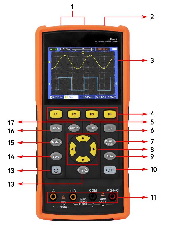
- CH1, CH2 measured signal input connector.
- Signal generator output connector (S type only).
- Display area.
- Press F1~F4 keys, multi-function keys, in each menu mode, press the corresponding key to select the corresponding menu item.
- Press the HOR key, you can change the horizontal time base setting by pressing the key, and observe the resulting state information changes, and you can also find that the horizontal time base display corresponding to the status bar has changed accordingly; by pressing the key, you can adjust the signal in the waveform The horizontal displacement of the window.
- Press the return key to return to the previous menu. When the menu is at the first level, press the return key again to close the menu.
- Measurement menu key (oscilloscope) or range key (multimeter).
- Zoom or move keys
- Autoset button (oscilloscope) or autorange button (multimeter).
- Stop/run button (oscilloscope) or hold button (multimeter) or output/close signal button (signal generator - S type only).
- Multimeter input.
- Trigger the menu key (oscilloscope) or the relative value key (multimeter).
- Power switch button.
- Enter the Save Settings button.
- Enter the system setting button.
- Button to switch the working status of oscilloscope and multimeter.
- CH1/CH2 channel switching button.
Oscilloscope
We used the ESP32 to output the audio signal, and plugged in a 200x amplifier circuit to the speaker. Attach the alligator clip to the horn to view the waveform
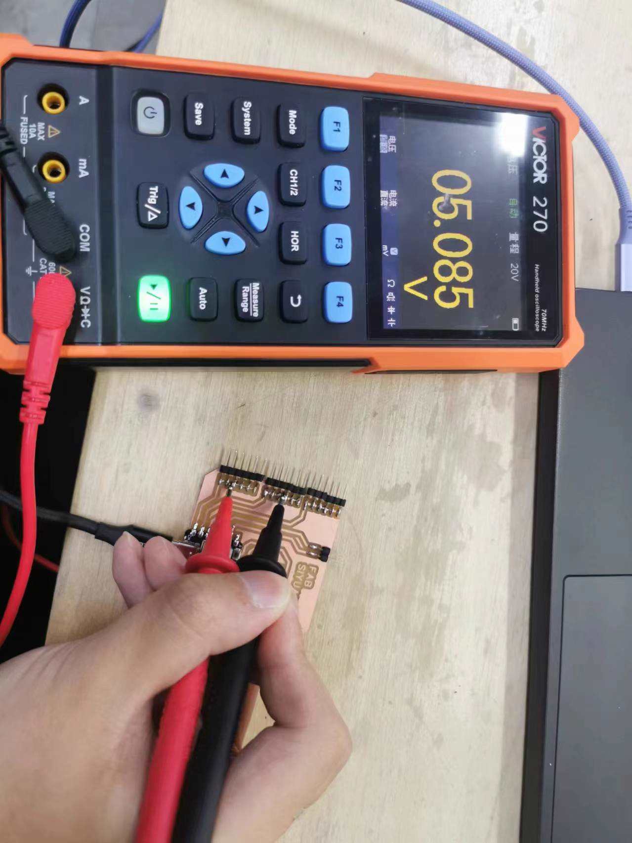
Multimeter
Press the “Mode” to switch to the multimeter function. Connect positive to VCC pin, negative to GND. Press F1~F4 to select the corresponding function.
What did I learn?
In this group project, I learned how to use a multifunctional tester integrated with both a multimeter and an oscilloscope. First, I output an audio signal through the ESP32 and connected a 200x amplifier circuit to a speaker, using the oscilloscope to view the waveform of the audio signal. Then, I learned how to switch device modes using buttons and measure voltage with the multimeter function, selecting different measurement modes using the F1 to F4 buttons. This project helped me become more familiar with performing various tests using both the oscilloscope and multimeter features of the same device.
Individual assignment
Easy EDA
Because my final project requires both WiFi and 4G communication, I used XIAO ESP32C3 as this week’s assignment. The EDA software used is EasyEDA.
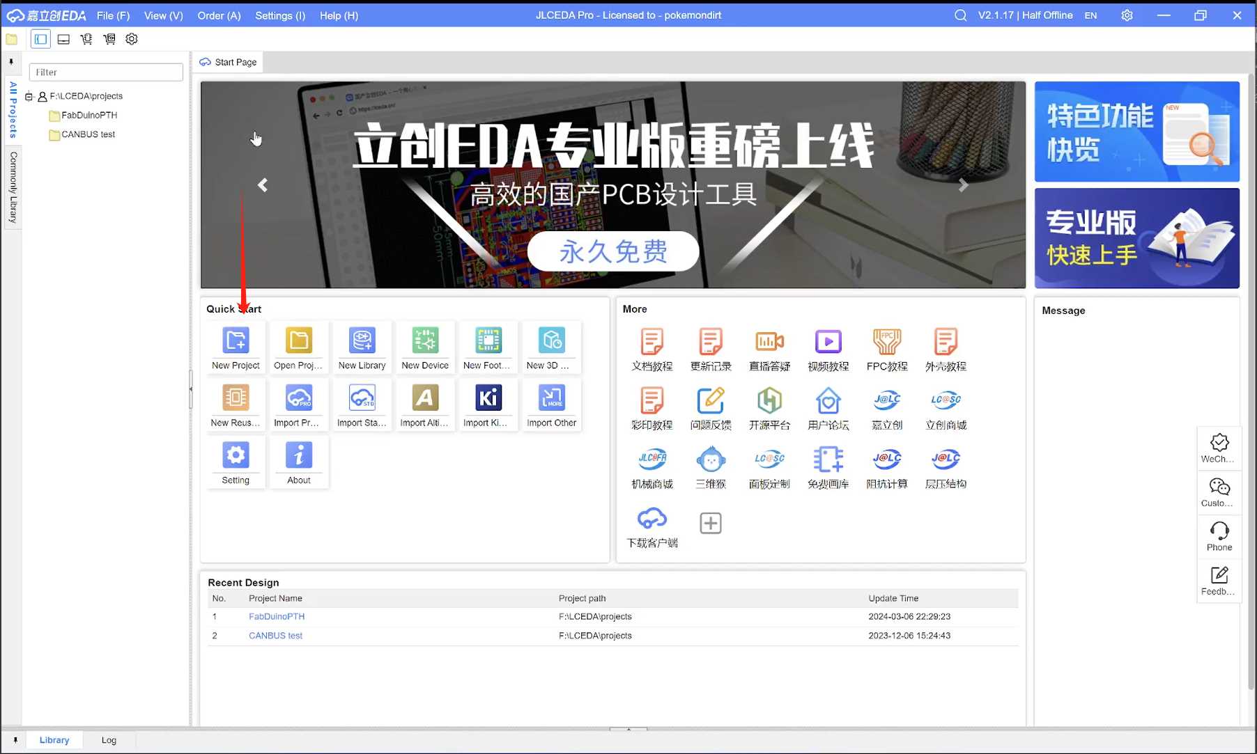
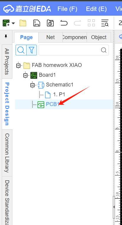
EasyEDA has a web version, so I chose to operate directly on the web page. First, I created a new project.
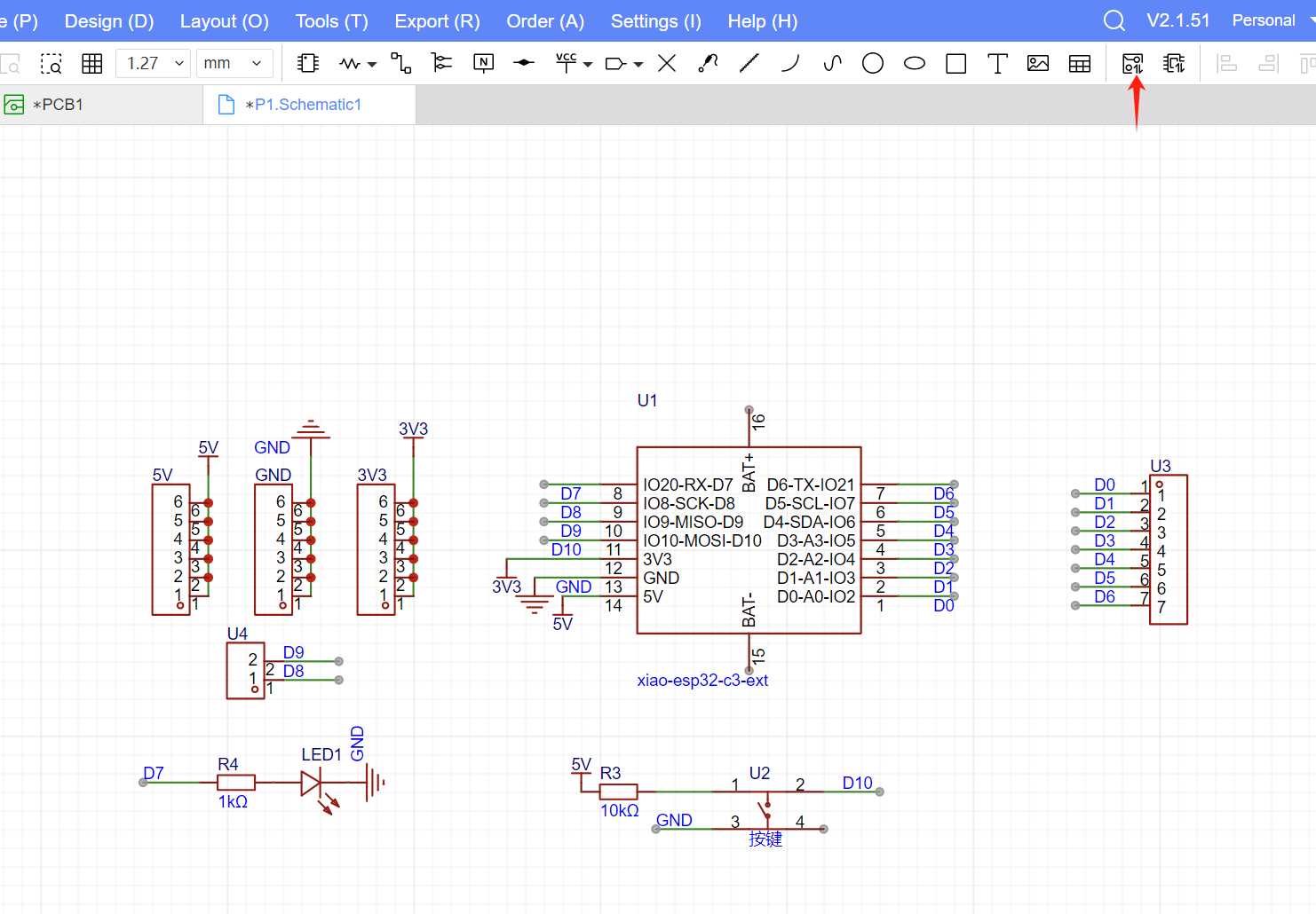
I used the built-in component library in EasyEDA to draw the schematic.
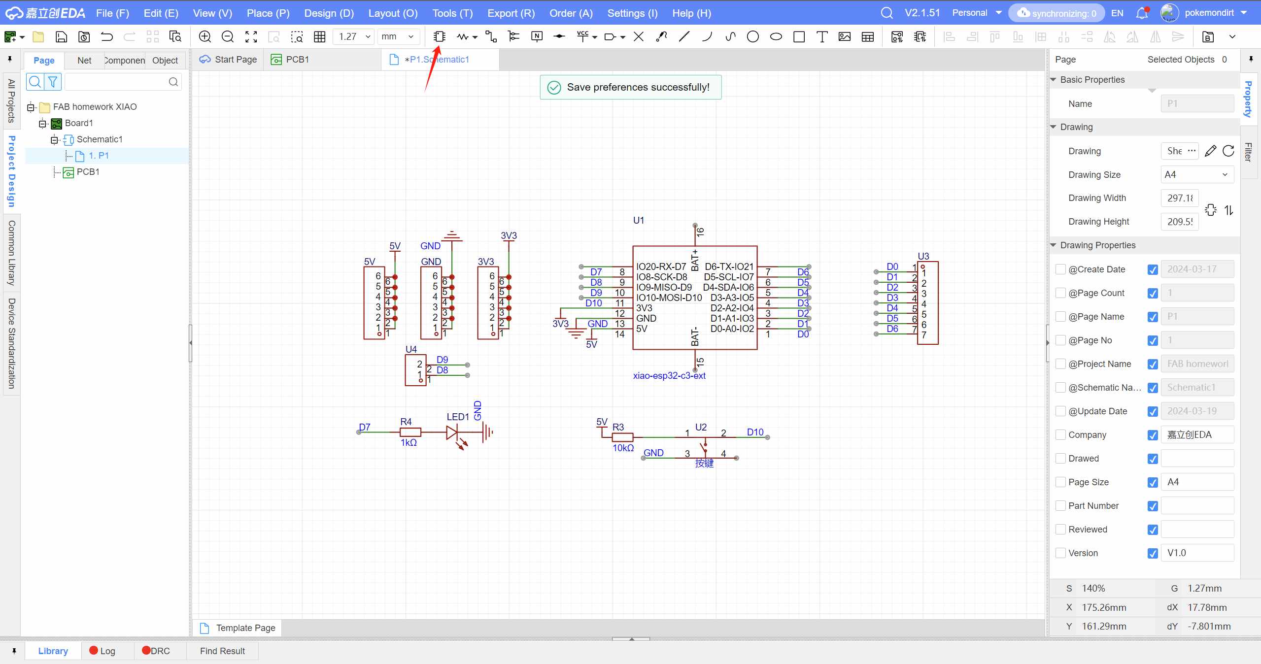
After finishing the drawing, click “update.”
Select the PCB view on the left side.
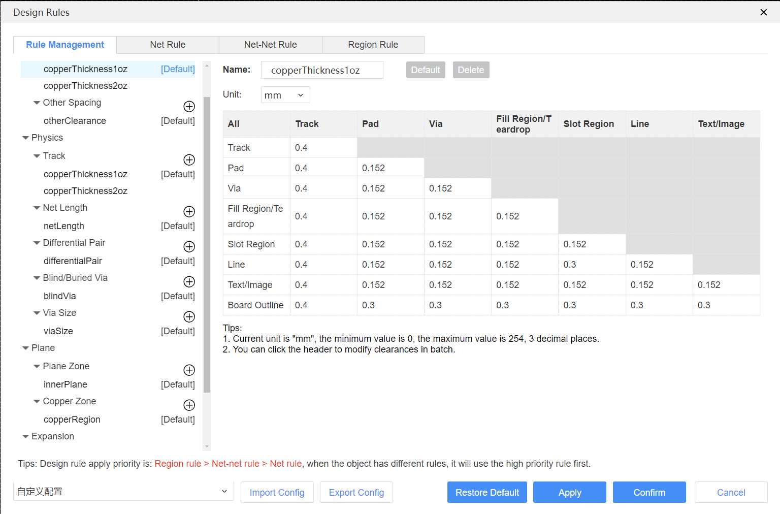
Before starting the actual routing, you need to set up routing rules.
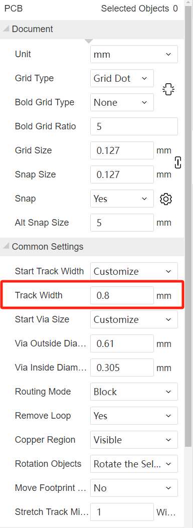
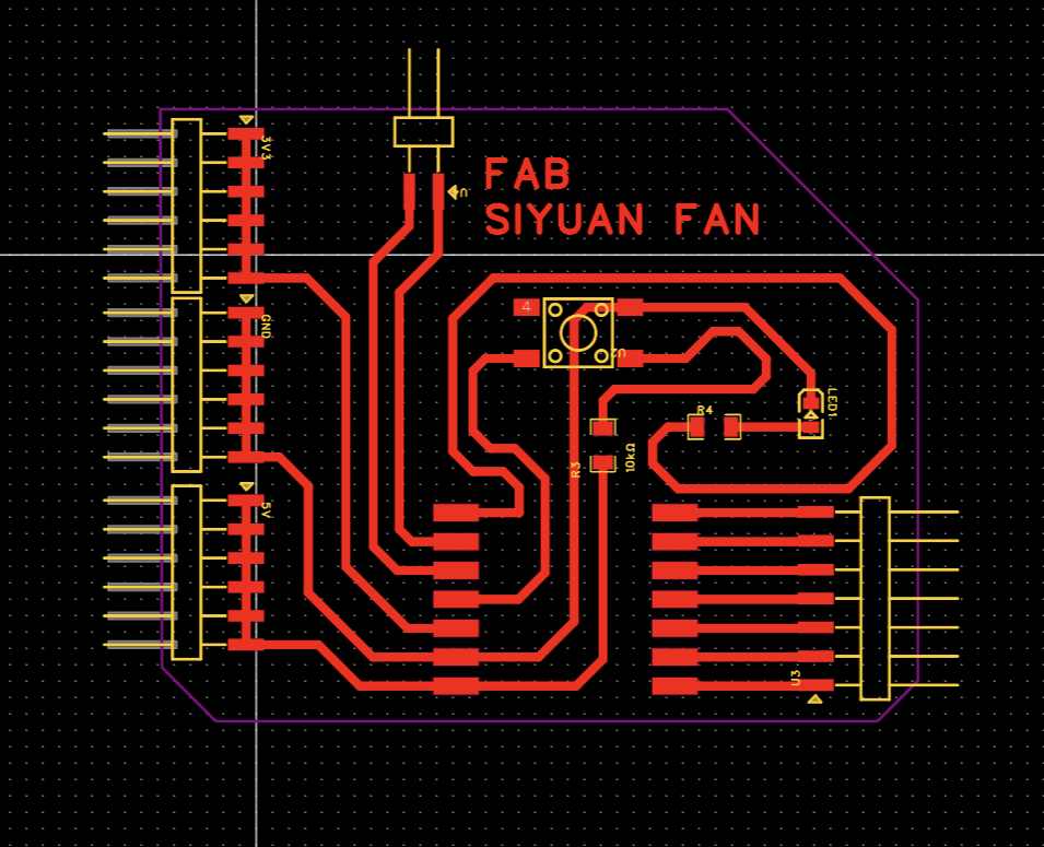
I set my trace width to 0.8mm.
This is the circuit board layout.
I used Mods CE to program the toolpath.Export the PNG and parameter settings. Please see the link below. mods CE Then I cut it.
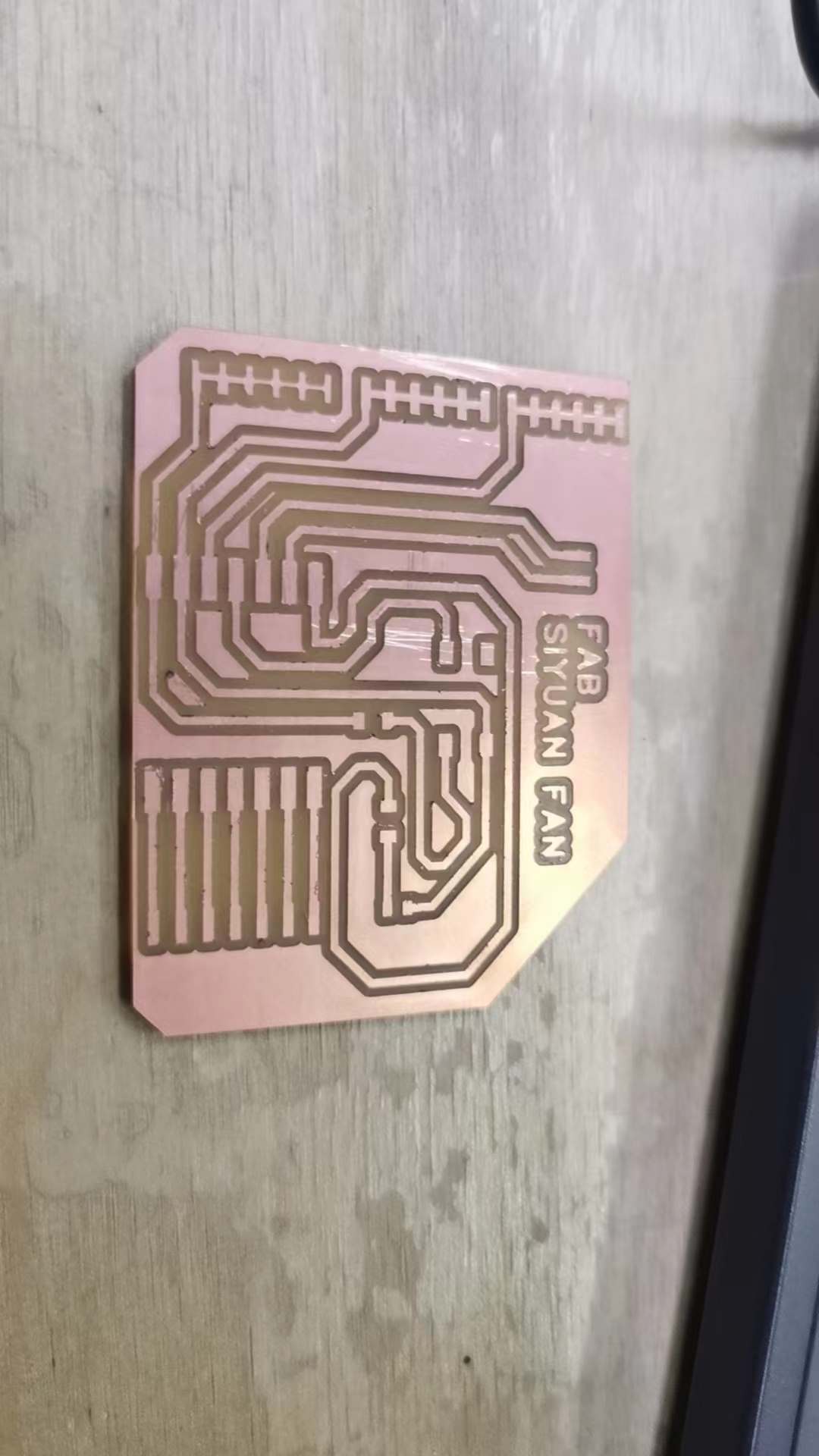
Done!
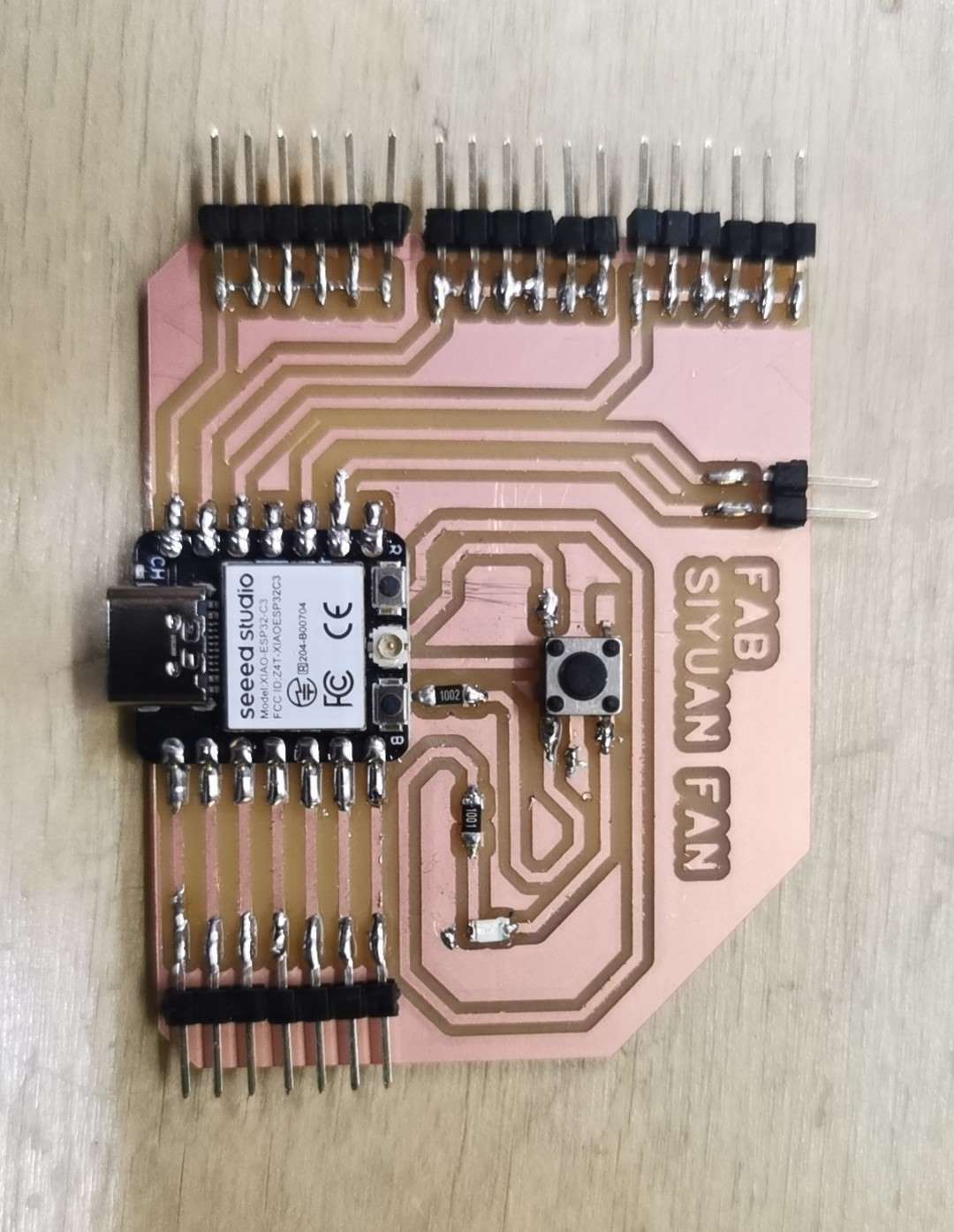
I connected pin 10 to the button and pin 7 for output. By programming, I can control the LED light.
The encountered problem.
During the soldering process, I found that the LED light was constantly on. Later, I discovered that my solder was bridged together. After separating them, it returned to normal.
sorce file