Output Devices
This week, I started working on the output section of my final project. For this part, I aim to implement an LED matrix, so I designed a new board for it.
1.1 Assignments of the Week
- Group assignment:
Measure the power consumption of an output device.
- Individual assignment:
Add an output device to a microcontroller board you've designed and program it to do something.
1.2 Group Work
time, we conducted tests using the GPS305D and a motor (3V-6V).
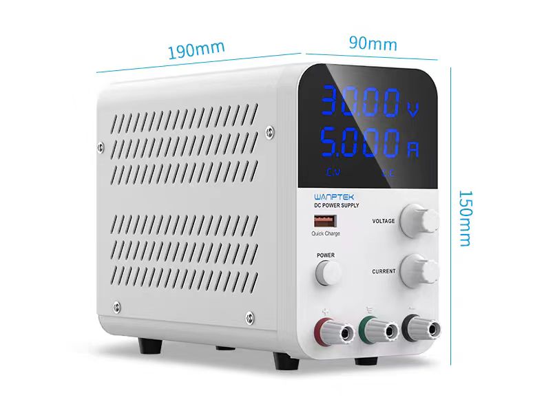
The GPS305D parameters are as follows:
Output voltage: 0--30V
Output current: 0--5A
Output power: 150W
Voltage regulation mode CV: continuously adjustable from 0 to the rated voltage
Current regulation mode CC: continuously adjustable from 0 to the rated current
We set the voltage to the commonly used 5V and then adjusted the current. After connecting the motor, we didn't have to worry about polarity since the motor doesn't have a specific positive or negative terminal. The final test results showed that under normal usage conditions, the voltage was 5V and the current ranged from 0.13A to as low as 0.05A.
The testing process is detailed below:
1.3 Individual Work
Since I had to make two attempts before succeeding, I won't go into detail about each step of my work; instead, I'll provide a brief summary.
The first mistake was quite amateurish. Initially, I naively attempted to connect multiple LEDs with just one resistor on the PCB board. It sounds impractical, but I wanted to give it a try, even though it was a nonsensical experiment. As expected, the LEDs failed to function properly.

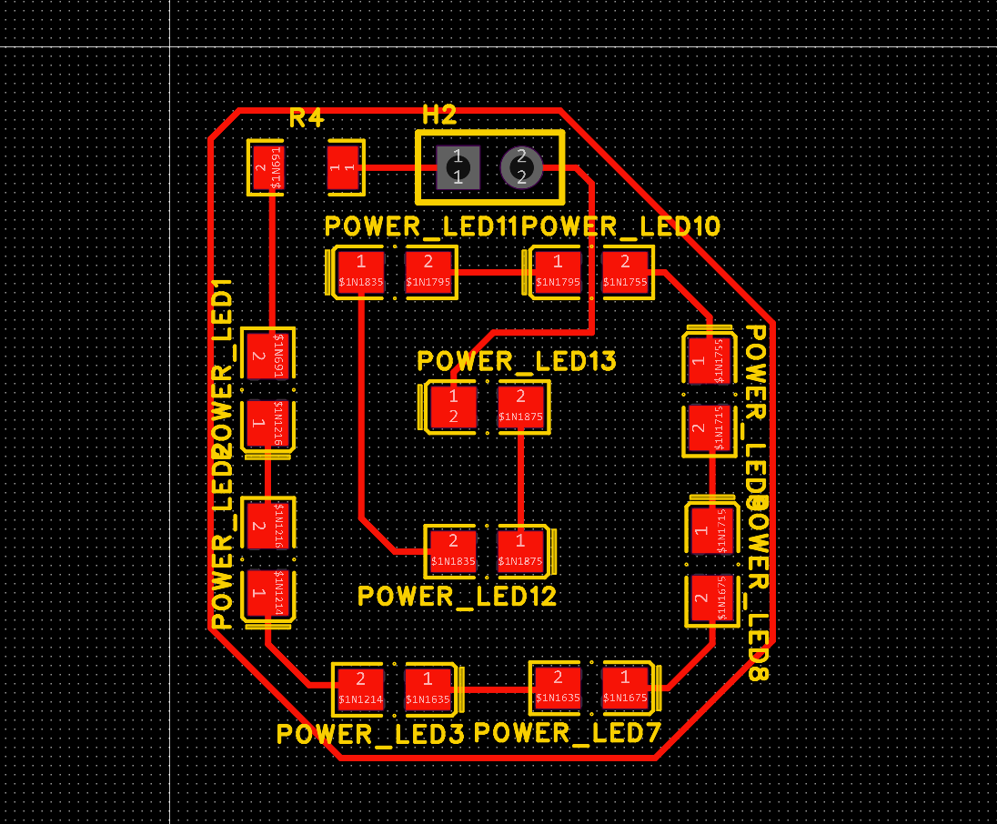
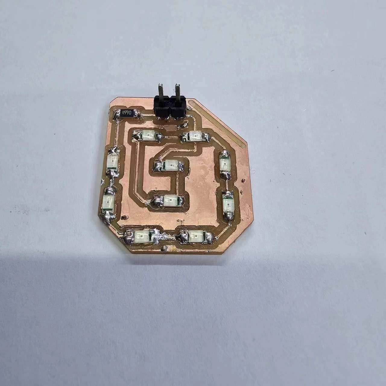
So, I did some research to fill in the gaps in my basic knowledge. In a series circuit, the voltage is the same for each LED (3V), but the current is the same throughout. In a parallel circuit, the voltage remains constant, but the current increases according to the number of parallel branches. Therefore, I combined multiple LEDs in series and then connected them in parallel. To ensure that the current doesn’t exceed the LED’s design specifications, I used a 499-ohm resistor to protect the circuit.This way, the voltage remains the same, but the total current reduce accordingly.
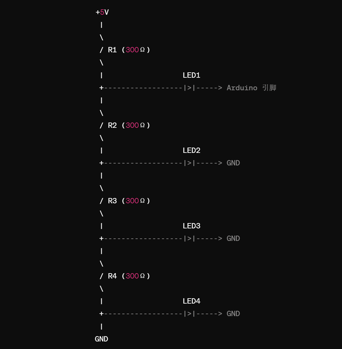
So how to illuminate 10 LEDs? I think a more complex circuit is needed. For example, dividing the LEDs into several series-parallel combinations, or using an appropriately sized current-limiting resistor to restrict the current, ensuring that the LEDs operate within a safe range.
So I embarked on my second design attempt, and this time it was a success!
My LED matrix consists of 10 small lights, which I divided into four pins for design purposes. The number of LED lights connected to pins 1-4 are 3, 3, 2, and 2 respectively. Each group of LED anodes is connected to the same pin (analog pin on the Seeed XIAO XP2040), while the LED cathodes are all connected to ground (GND). Each group has a 499 ohm resistor to limit and protect the LEDs.
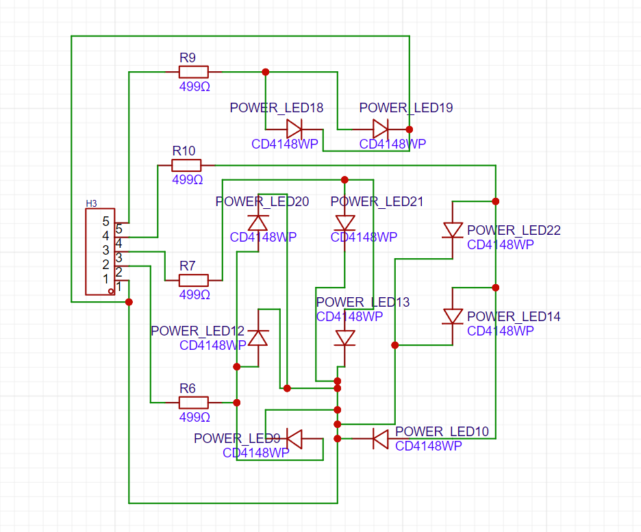
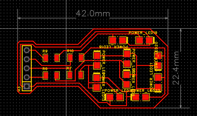
Then I started the EDA design, where I drew ten bulbs and four resistors along with five connection points in the schematic. Next, in the PCB layout, I designed it to resemble the shape of a light bulb. Lighting up the small lights would mimic the glow of a light bulb, with a "filament" dancing inside the bulb.
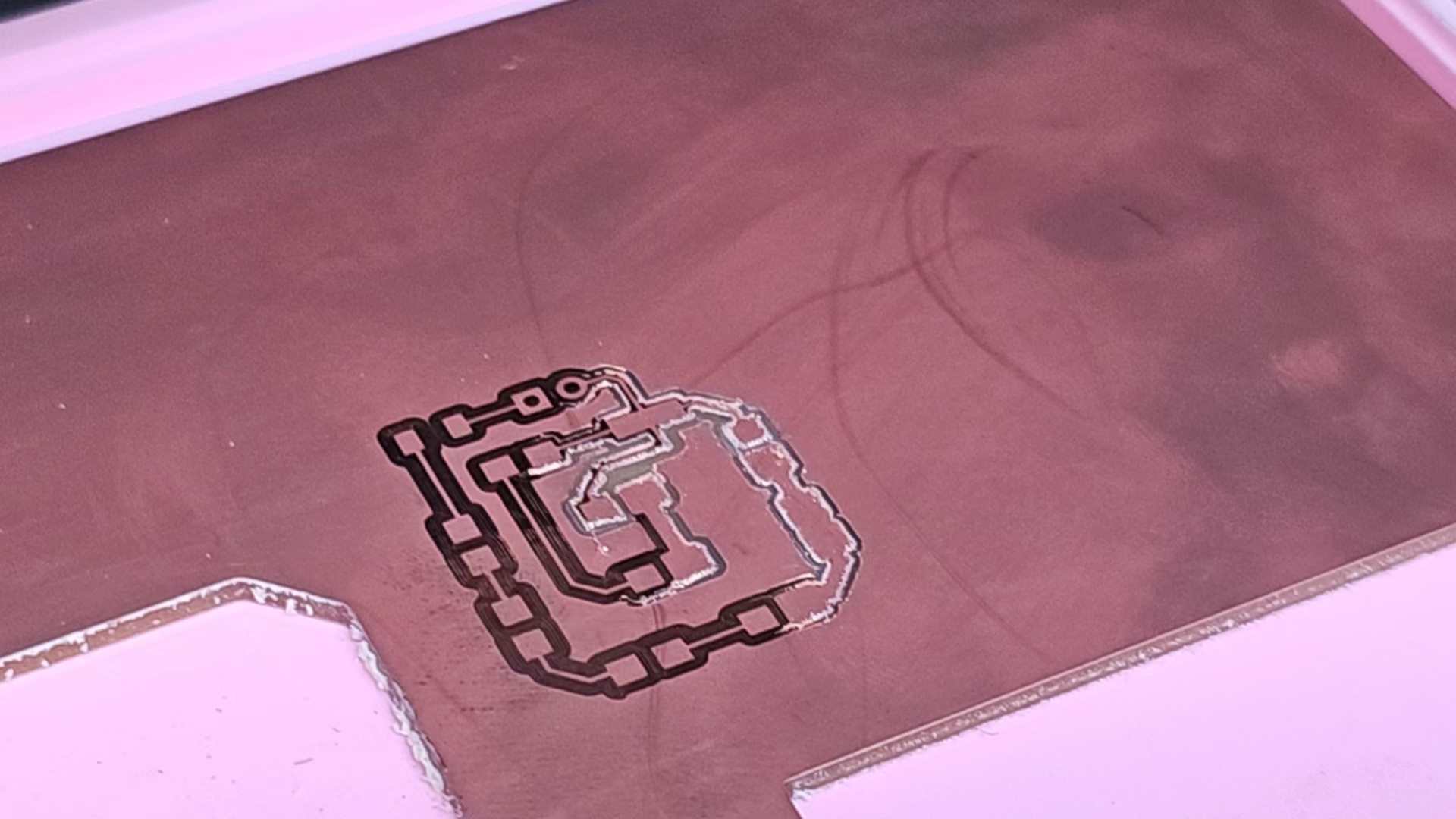
As I did last week, I split the PCB into three layers in Photoshop, then I traced the routes for all three layers in Mods. After exporting, I proceeded to milling with Roland. Milling turned out to be the final straw that overwhelmed me.
The first straw: Here, I have to say that I need to exercise more, because after two modifications, the chuck of the tool is very tight, and it is very strenuous to constantly remove and replace the milling cutter. I kept thinking about the force method that Nancy taught me, and finally succeeded, but my hands were also squeezed and hurt... I wish that one day the studio will have an automatic chuck, and of course I also need to exercise more! !

The second small problem: When milling for the first time (using a faulty circuit board), the back half of the milling process was not cut through. I checked that all the parameters in Mods were set correctly and confirmed that the Z axis was fine. However, the copper layer was still not completely cut through. I patiently let it run a few more times and observed.
Maybe there are two reasons: ① The glue density behind the copper clad board is different or the gap is too large, causing this area to collapse a little; ② The copper clad board itself has incorrect precision (an unknown Taiwanese brand...)
Then I increased the cutting depth by 0.03 mm and re-uploaded it, and it finally succeeded!
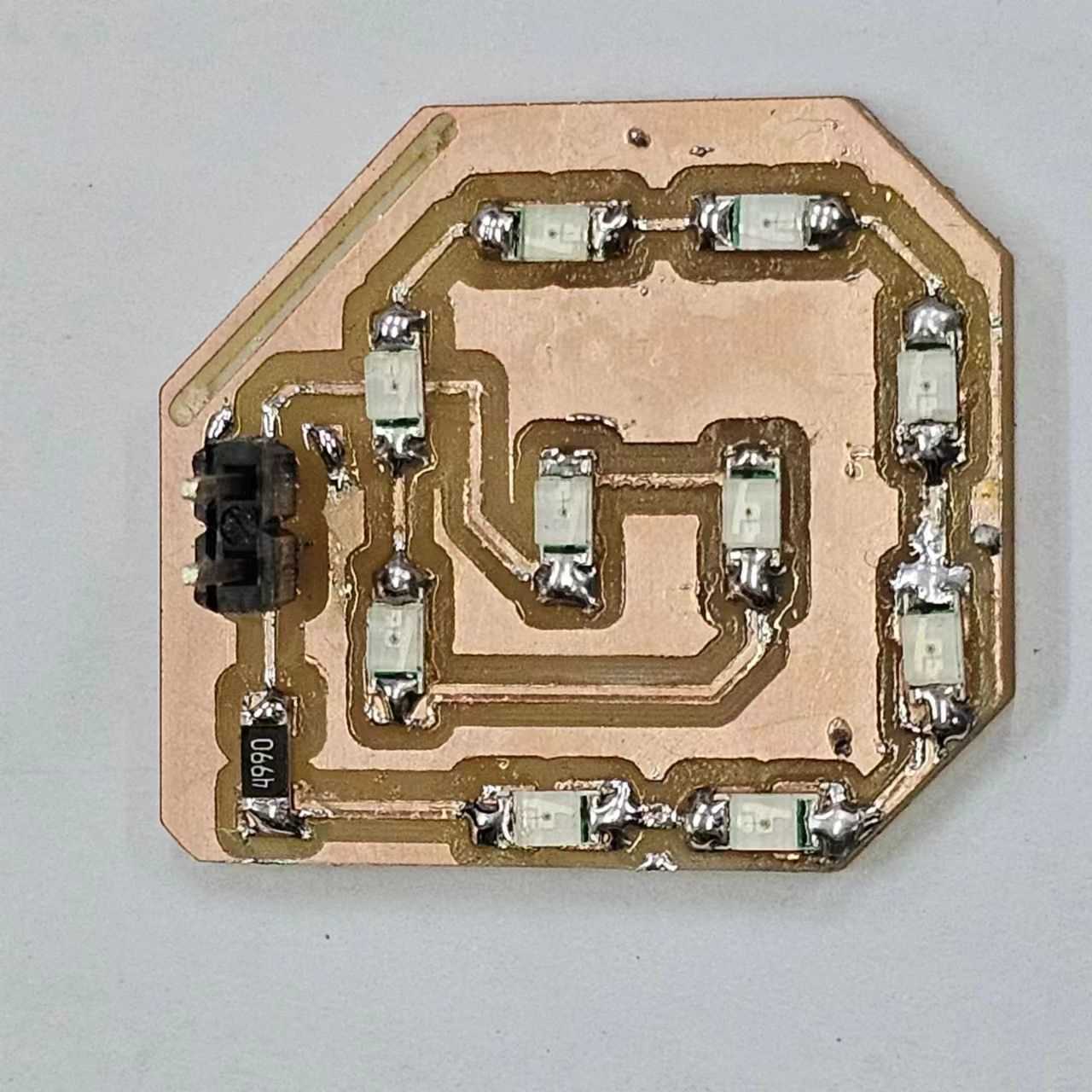
Then came the soldering part. To avoid waste, I removed everything from the first faulty board and soldered it onto the second board. It looks pretty good!
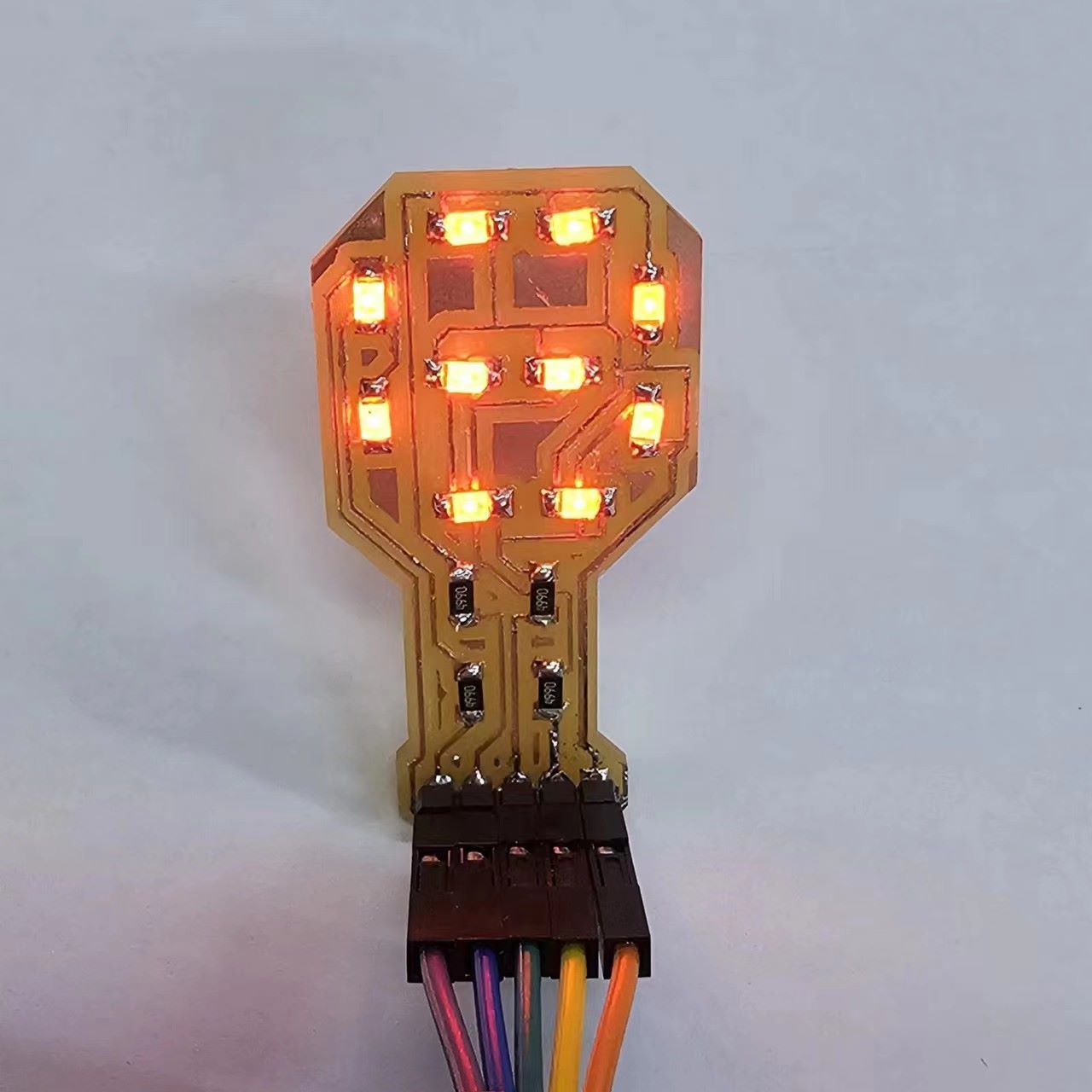
Programming! I wrote two simple codes, which I'll share at the end. The first one simply controls the LED's high and low states. I put it inside a folded paper lantern. When you look inside from the small opening, it feels like entering a breathing space.
The second one follows the circuit I designed, lighting up the LEDs in sequence. It didn't achieve the effect I wanted of one LED lighting up after another. I'll explore further later.
Overall, it looks fine. However, after attaching it to the board, the pin on the 26th pin seemed a bit loose, causing intermittent poor contact. It was resolved after I replaced the wire.