Final Project
This is a weather-themed pointer designed to add a bit of surprise and joy to daily life with an engaging weather display. Although weather is an "invisible influencer" we can't control, this device brings it to life in a fun way. I visualize the weather by connecting to Wi-Fi and obtaining local weather data. When the weather changes, a weather indicator will climb up like a ladybug, making each day more interesting. It will make us subconsciously wonder: what will tomorrow's weather be like?
Summary Slide:

Video:
[Hero shot]
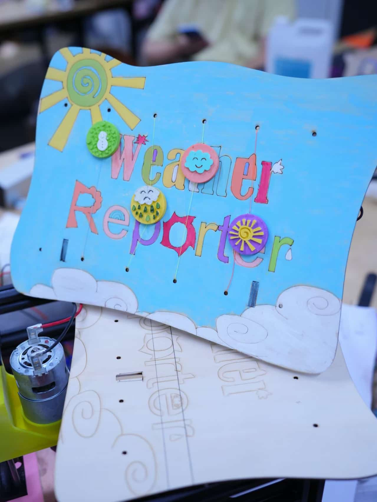
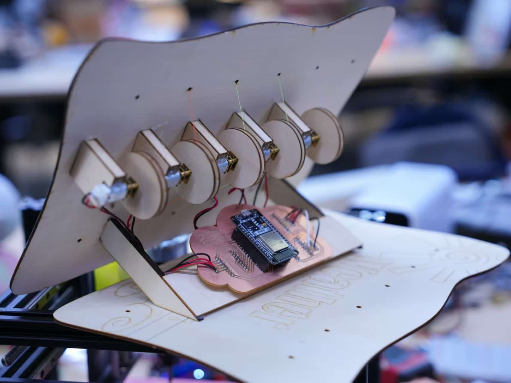
My concept is to design the device in the shape of a photo frame, with a stand on the back to support it, making it suitable for placement on a cabinet or desk. This aligns with natural viewing habits, allowing people to easily observe the weather movements from a top-down perspective. This setup not only makes it convenient to view but also adds a decorative element.
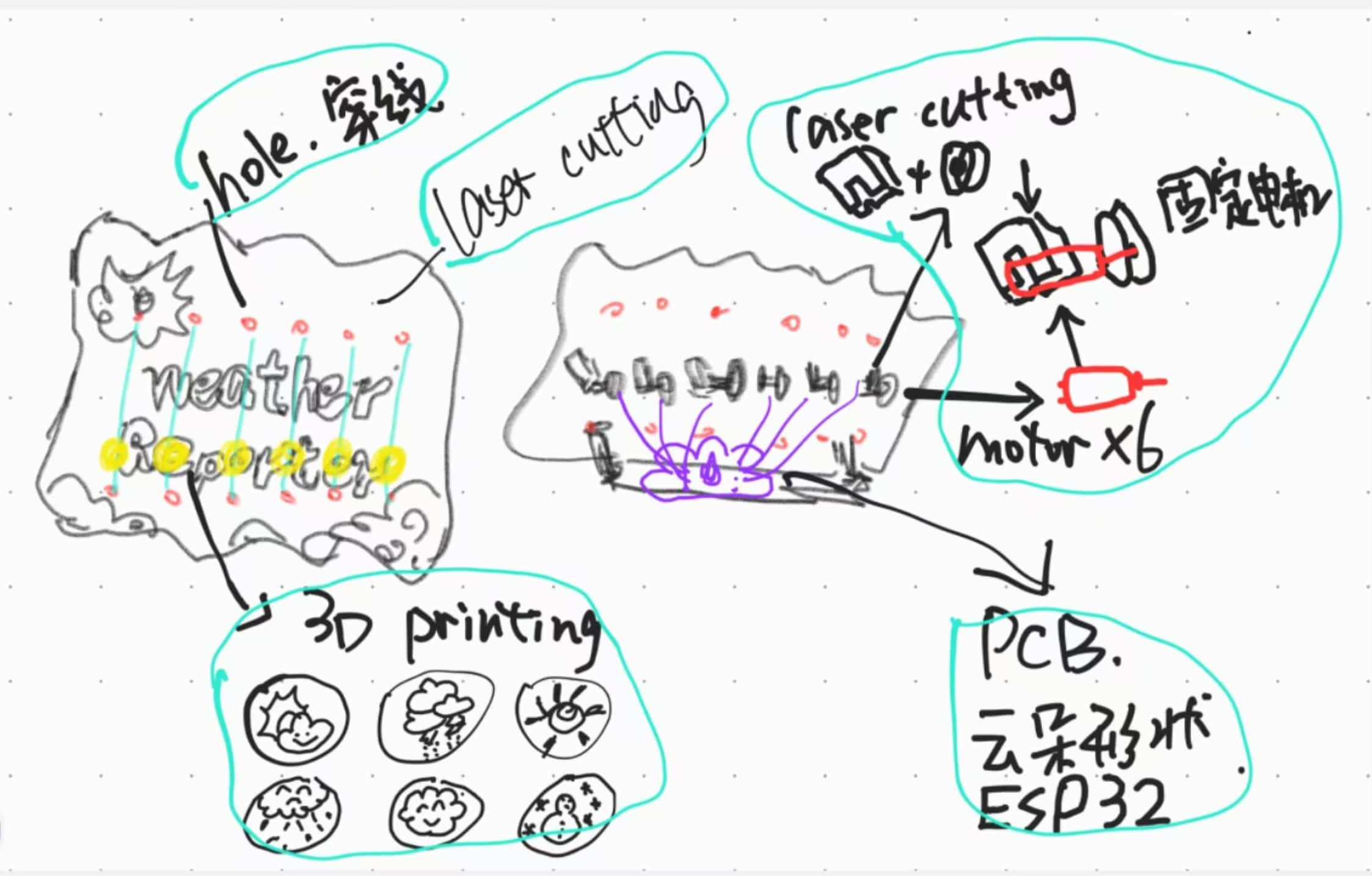
For specific details: the back panel and motor drive bracket will be laser cut. The drive bracket is designed to securely hold the motor, ensuring that the weather icons can smoothly move up and down to simulate the dynamic changes in weather. These weather icons will be 3D printed to enhance their three-dimensional feel, making each icon vivid and engaging.
For the electronics, a cloud-shaped PCB board will be designed using EDA software. The stand will not only support the entire device but will also fix the PCB board in place, creating a simple and sturdy overall structure.
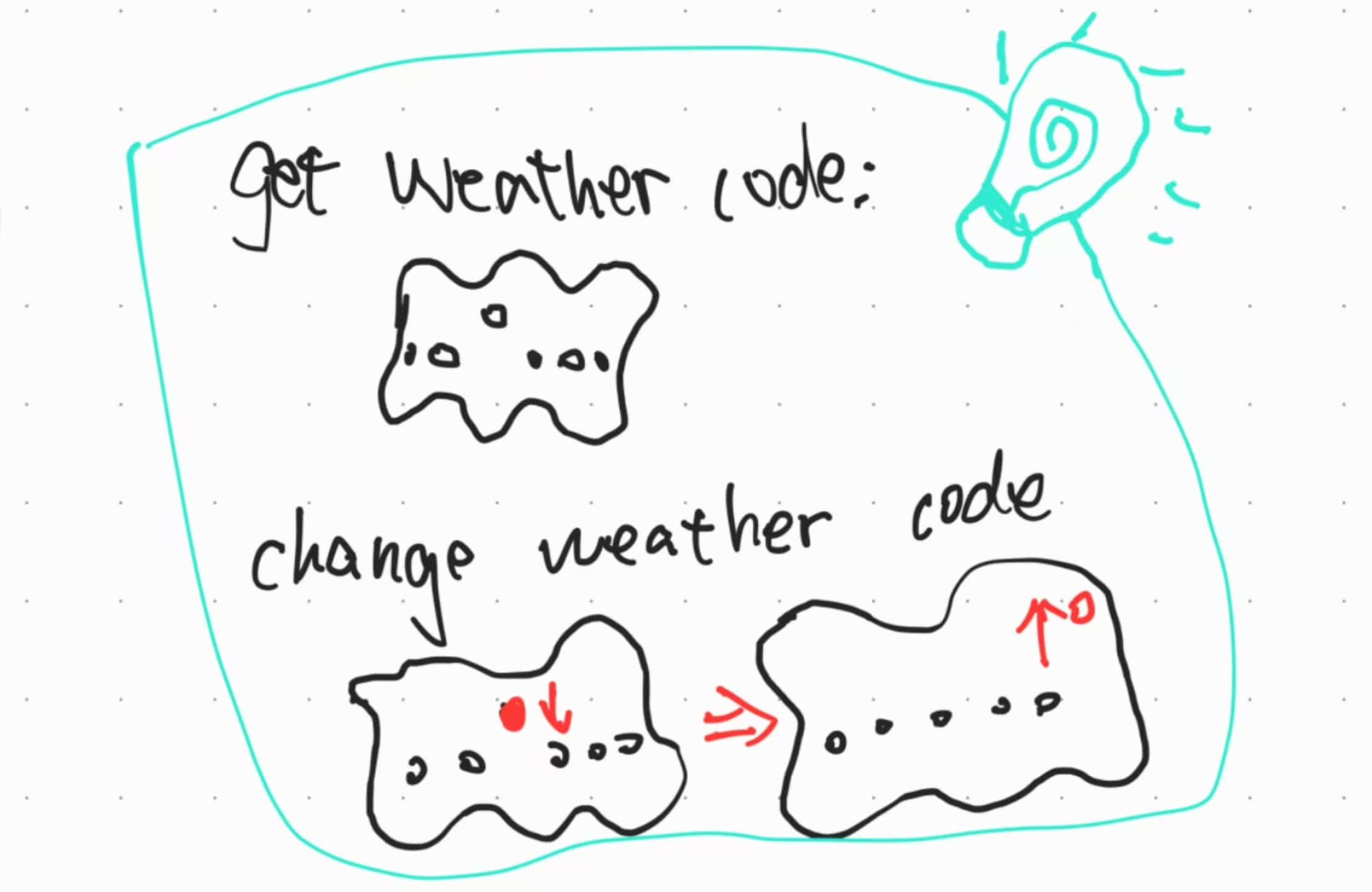
Upon powering on, the system will initialize, resetting all weather icons to zero position, neatly aligned at the bottom. Each time a new weather code is received, the system will move the corresponding weather icon upward to the center of the "frame" for easy top-down viewing. When the weather changes, the currently displayed icon will gently descend back to its starting position, while the new icon smoothly rises to settle in the display area.
3D Modeling and Printing
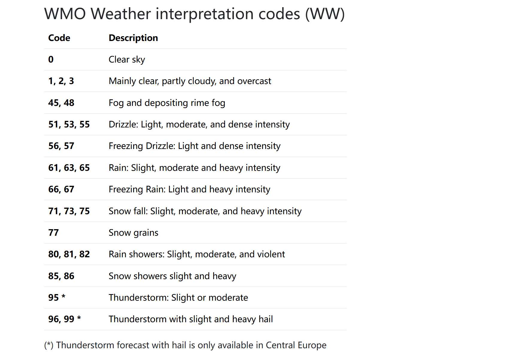
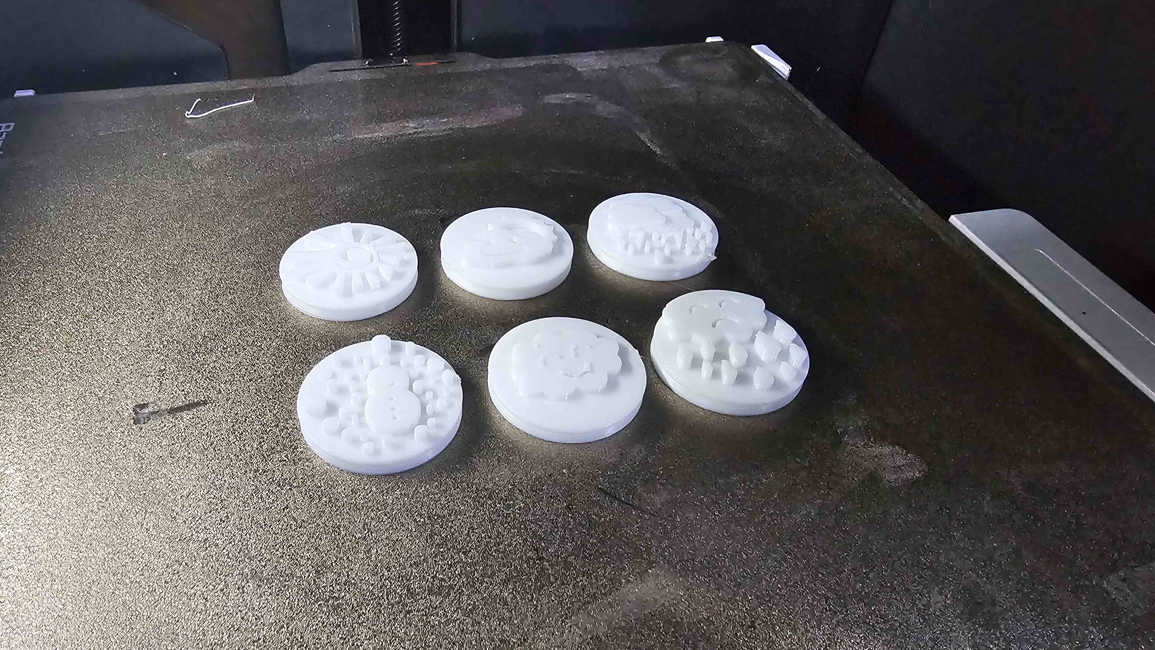
I checked the weather variable codes on OpenWeather and classified all the codes into 6 groups, each represented by a corresponding weather icon. For example, clear sky and the clear code, 0 and 1, both belong to clear weather, so they are grouped into the first group and represented by a sun icon
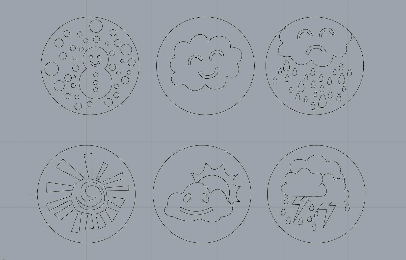
For the design, I used Rhino’s curves and control points to assist in the modeling, which turned out to be great.
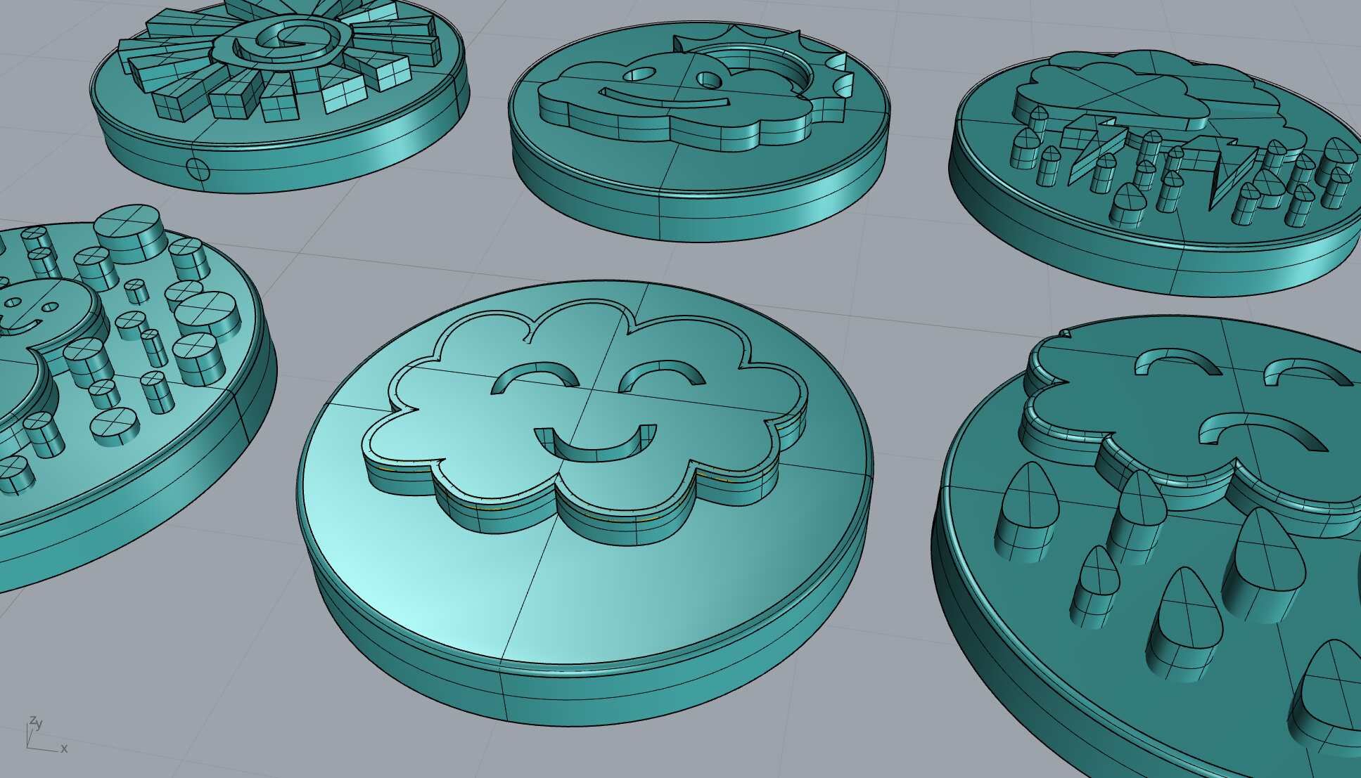
I then extruded the curves to create solid models and rounded the edges for a more visually friendly appearance.
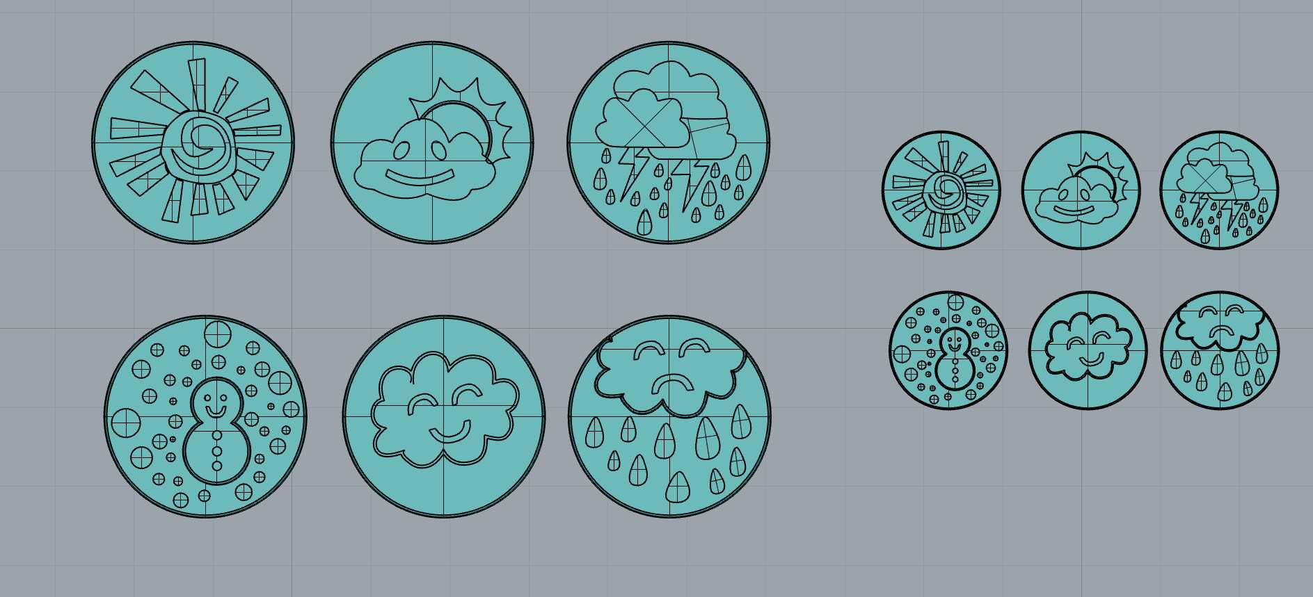
Two versions were made, 2525mm and 1515mm. After printing, I compared the results and needed to consider the motor position and PCB size.
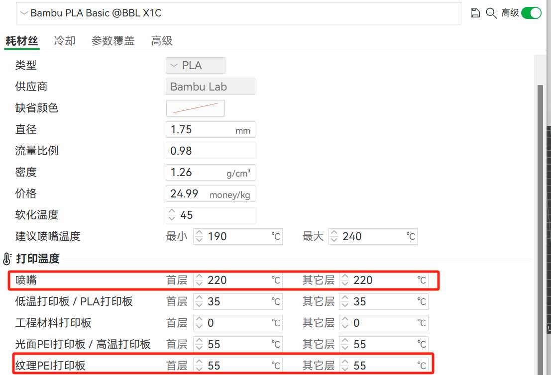
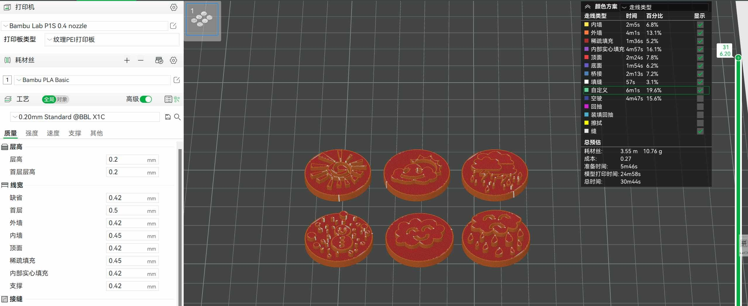
In Bambu Studio, I sliced the models. I used the Bambu P1S with white PLA filament. Based on the weekly testing results, the print temperature was set to 230°C, with the heated bed temperature at X. The printing time for the 2525mm version was 30m44s, and for the 1515mm version, it was 14m47s.
Uploading and waiting to print...
Success!
2D Design and Laser Cutting
Using motors and the two sets of printed weather icons, the 25*25mm version provides a better visual effect. I used LaserMaker to create the 2D vector drawings.
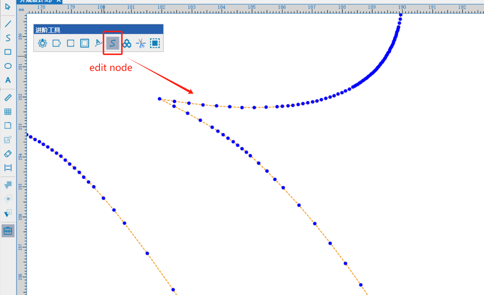
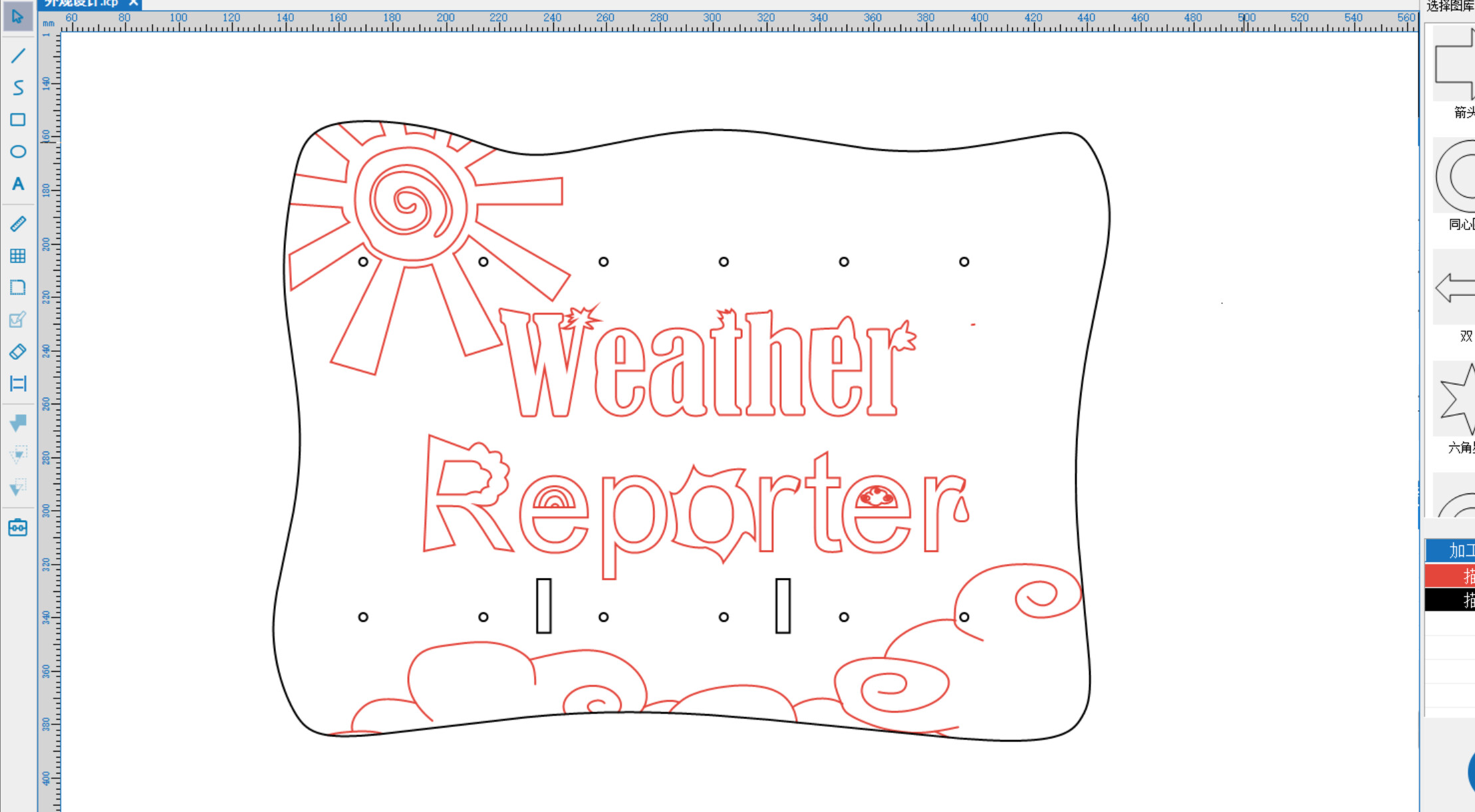
Back Plate Design: The back plate measures 313*231mm, with cutouts for the drive mechanism to pass through. The text section is designed using editable nodes for a fun and creative touch.
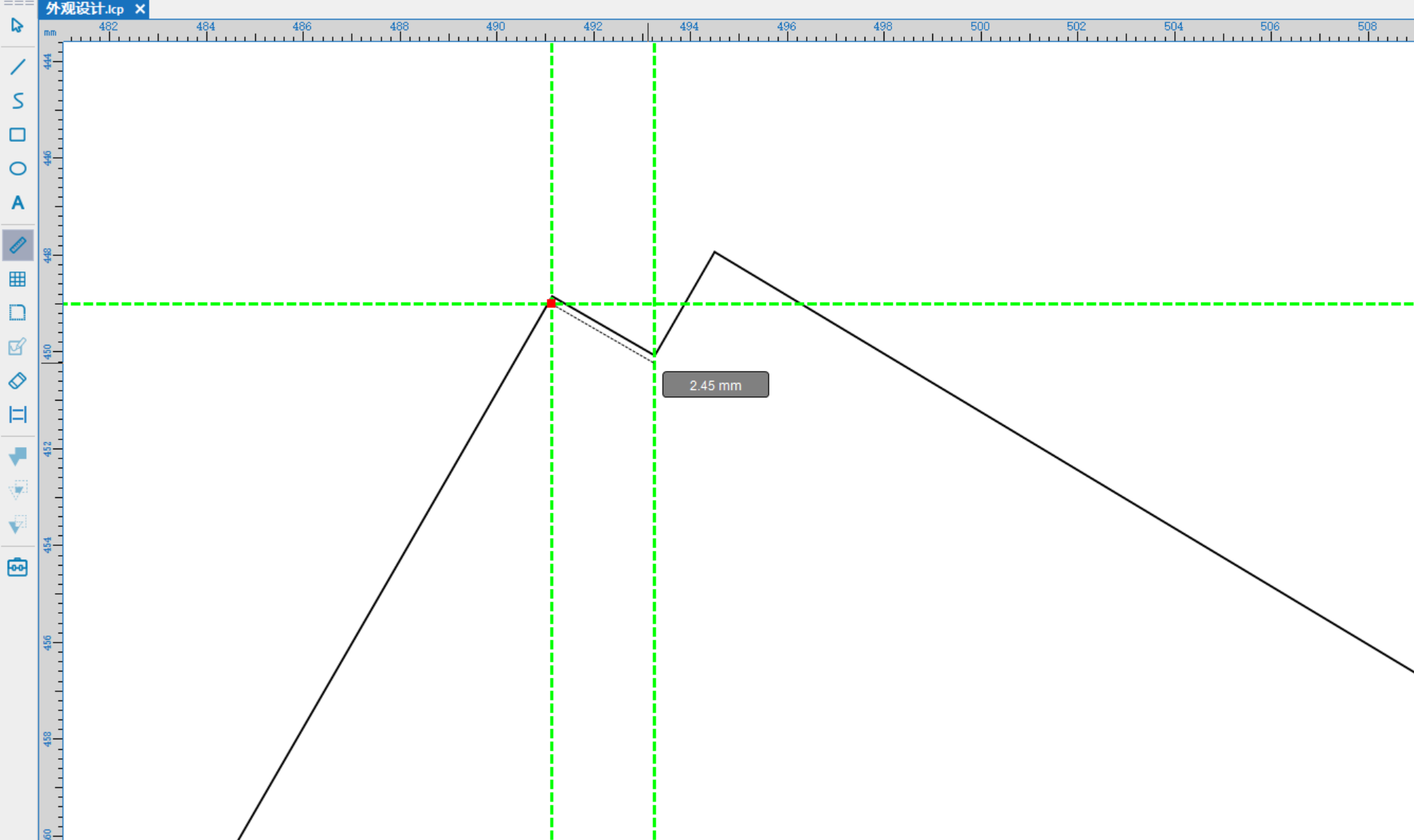
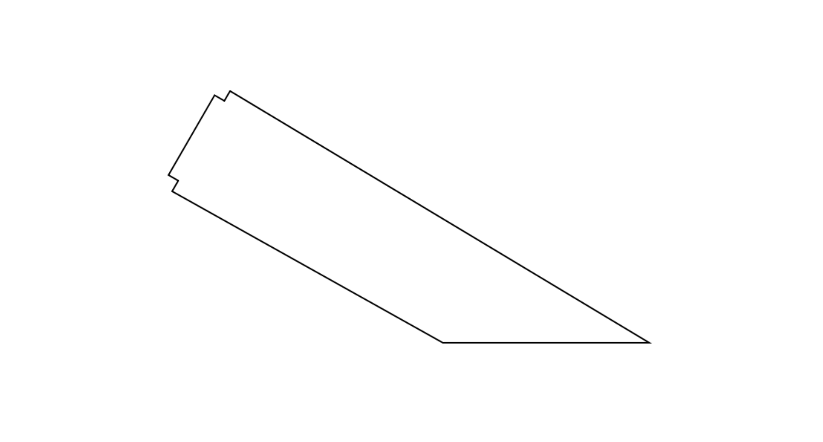
Bracket Design: Considering the angle from which people will view it from above, I designed a slightly tilted support angle. Fixed holes were added, and based on the Week 3 joint test, I ensured that the bracket would securely connect to the back plate.
Drive Bracket Design: I designed the motor mounting position and the guide groove for the transmission. When the motor starts, the guide groove rotates, causing the icons to move up and down.

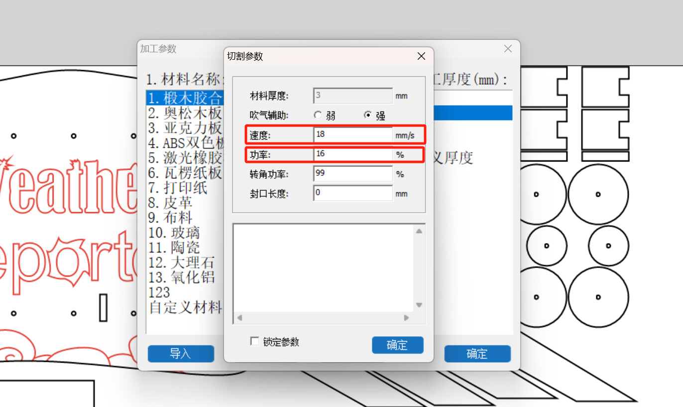
Laser Cutting: I selected 3mm linden wood, adjusted the stroke and cutting layers, with a power setting of 18% and a speed of 16mm/s.
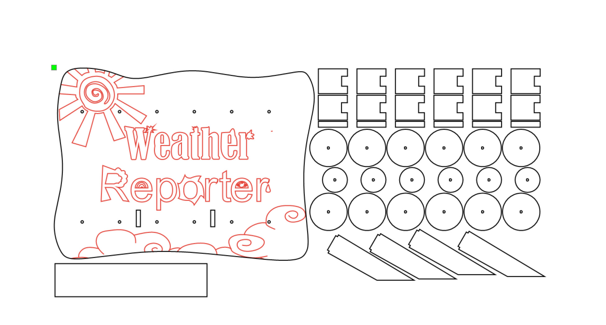
Starting the cutting!
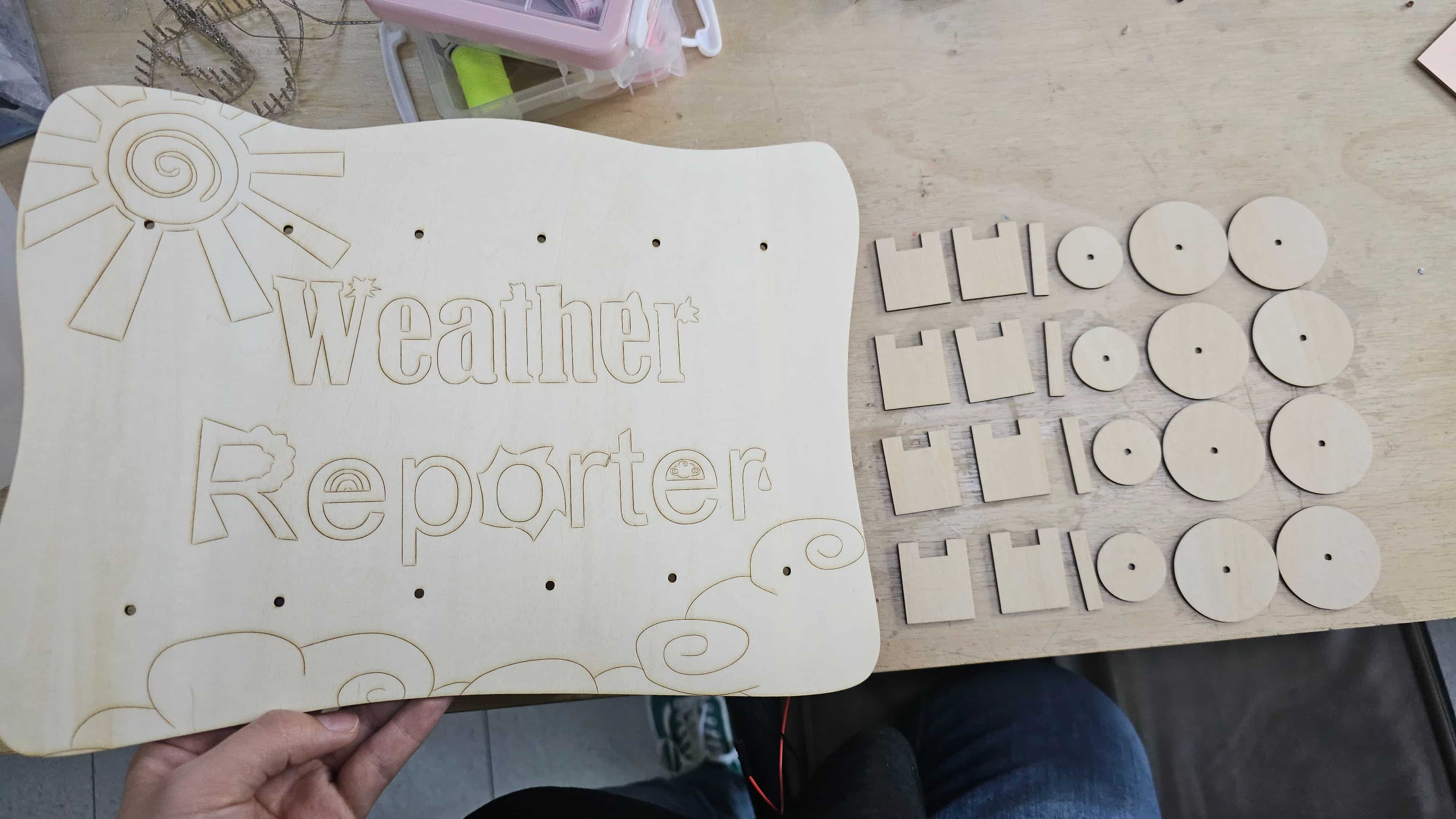
I tested the assembly to provide a stable angle and a proper area for the weather icons to move smoothly.
PCB Design 、Milling and Soldering
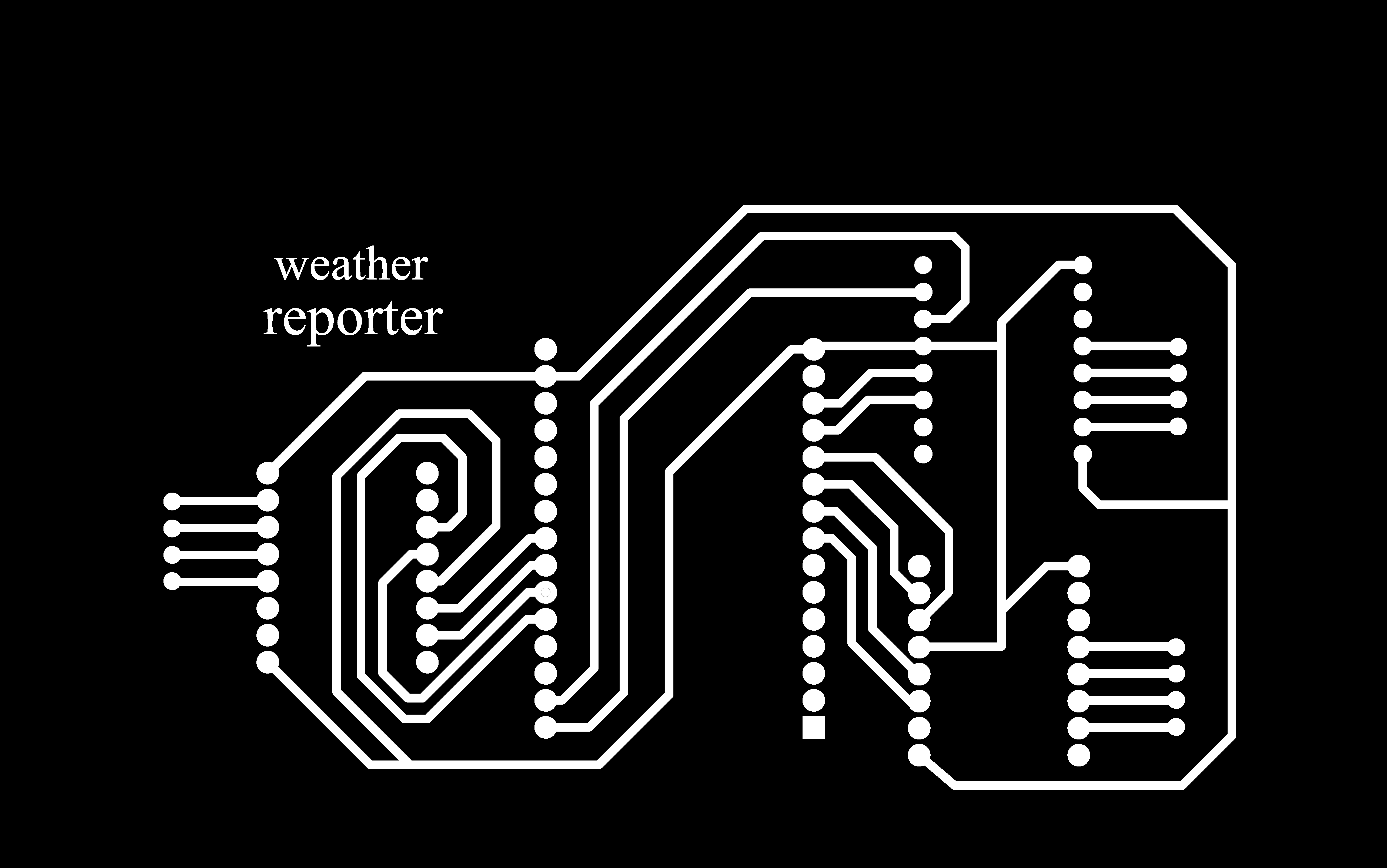
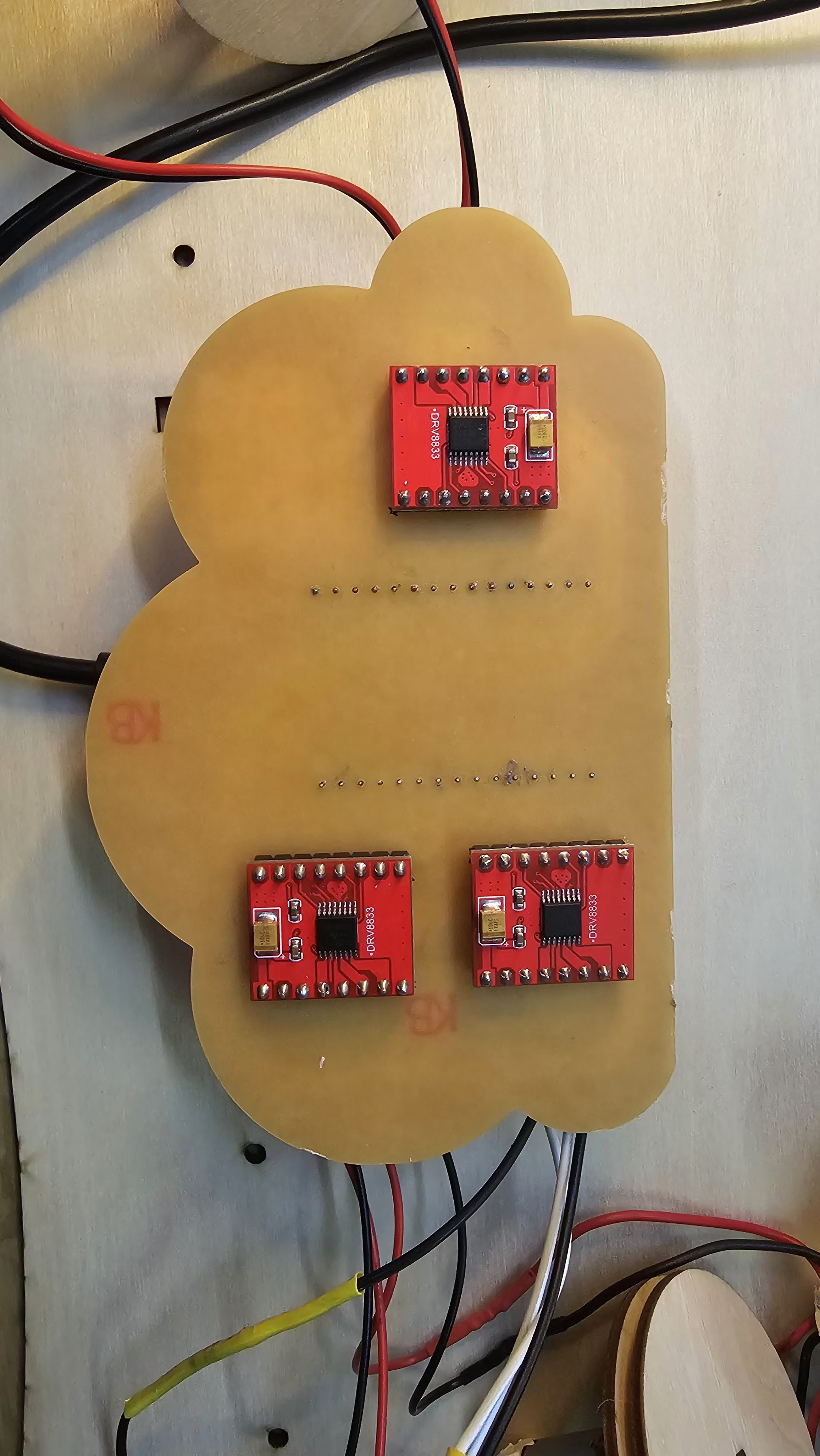
I designed the PCB in EDA, and here are the schematic and PCB layouts. I'm really grateful for the learning in Week 08, as it made this design process much easier. Since my PCB consists of an ESP32 and three DRV8833 Motor Driver Boards, soldering directly with the existing pins was extremely difficult. Plus, after soldering, there would be a lot of solder around the pins, and I didn’t want it to look messy. So, I decided to solder the Motor Driver Boards in reverse (thanks to my experienced partner for the advice!).
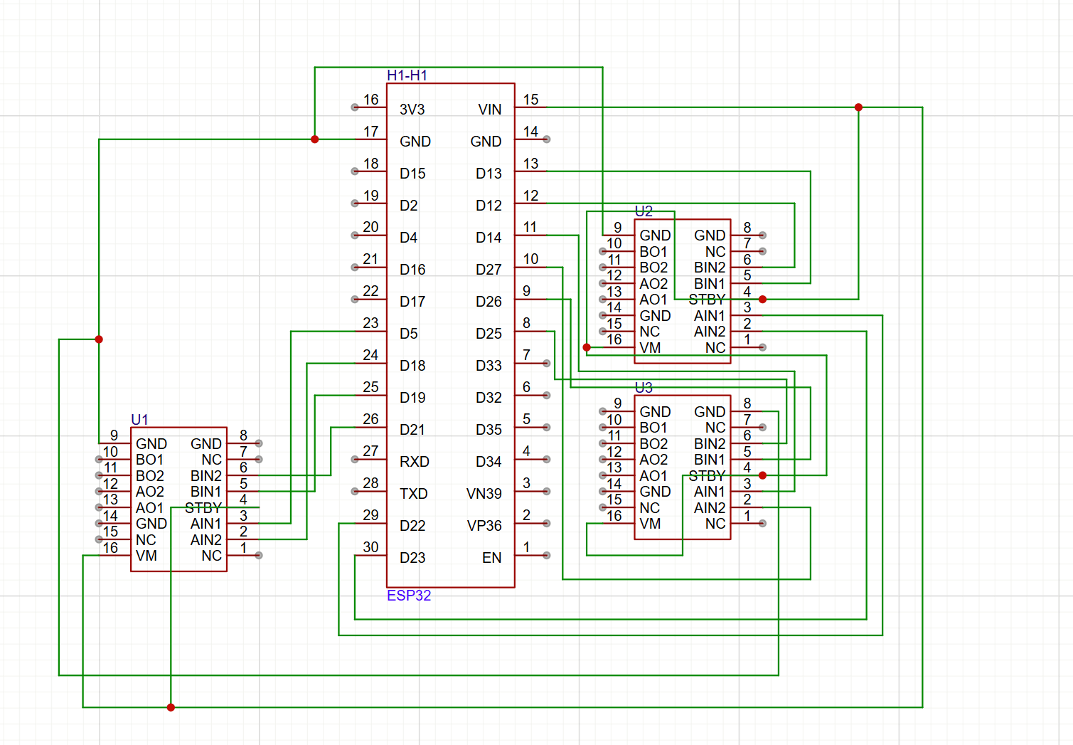
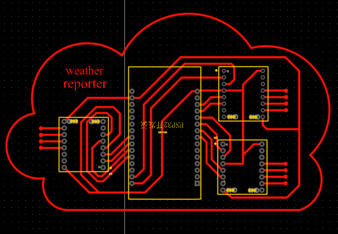
Exporting PDF
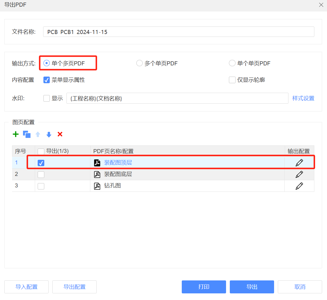
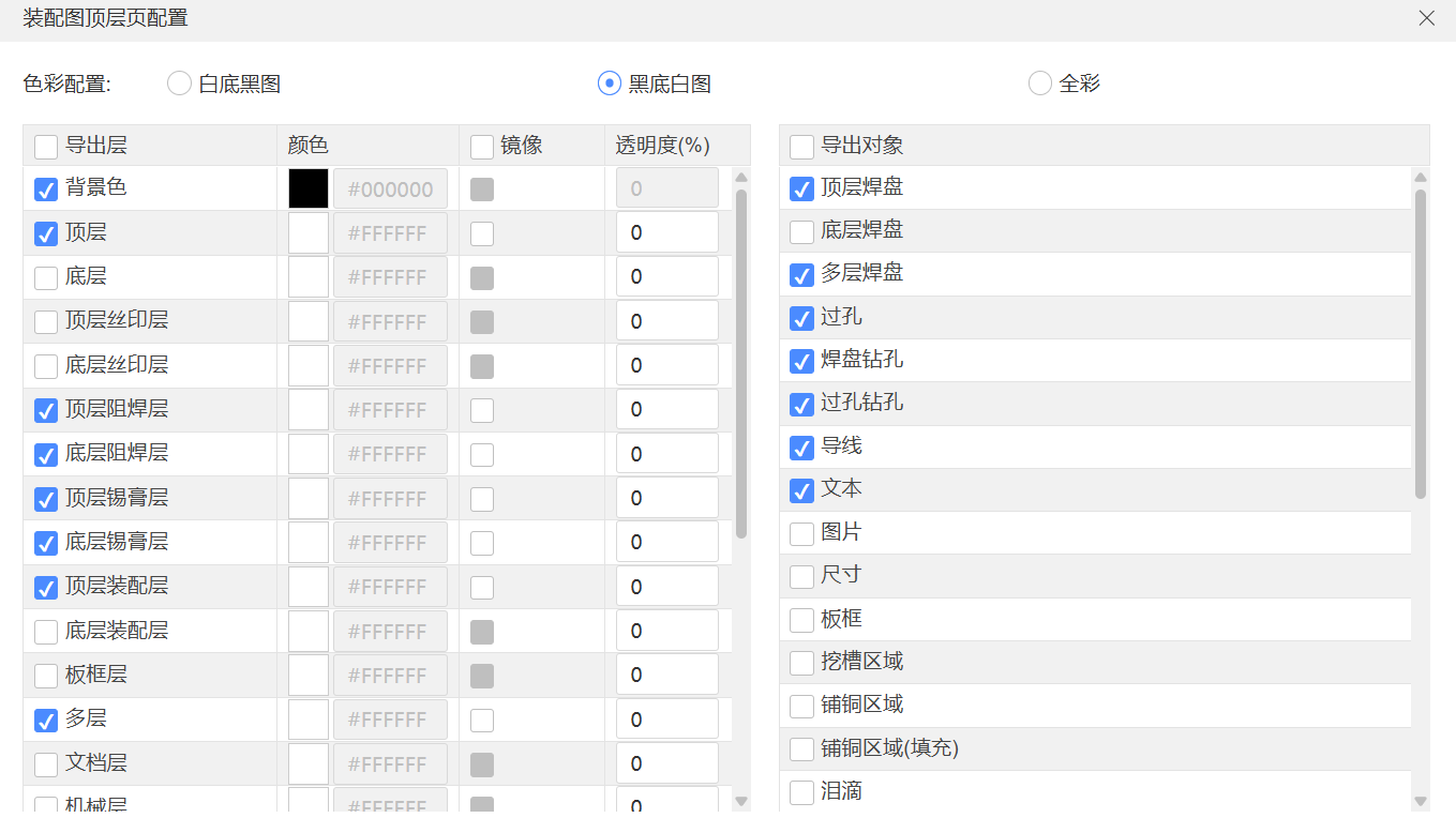
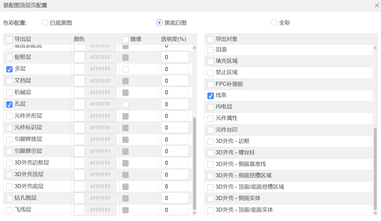
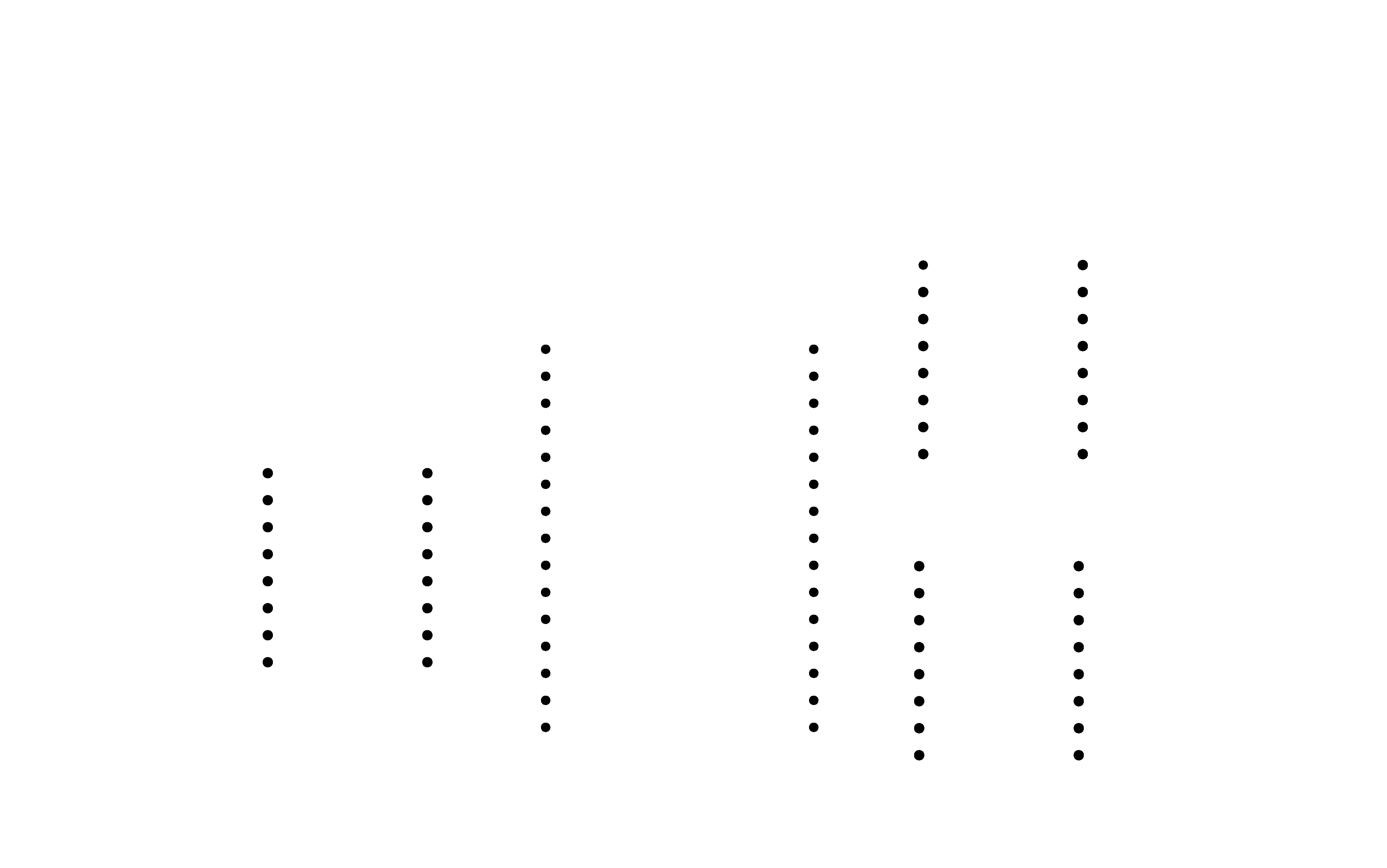
In Photoshop, I used the paint bucket tool to process the design: the white background represents the areas to be kept, and the black background represents the areas to be milled.
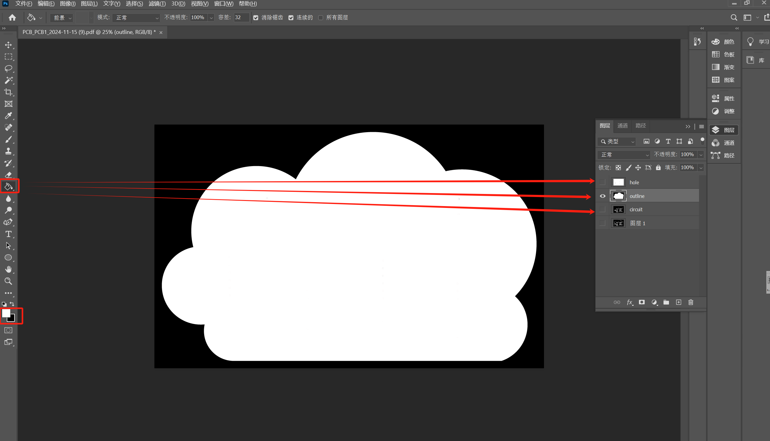
I exported the circuit, vias, and outline layers in PNG format.

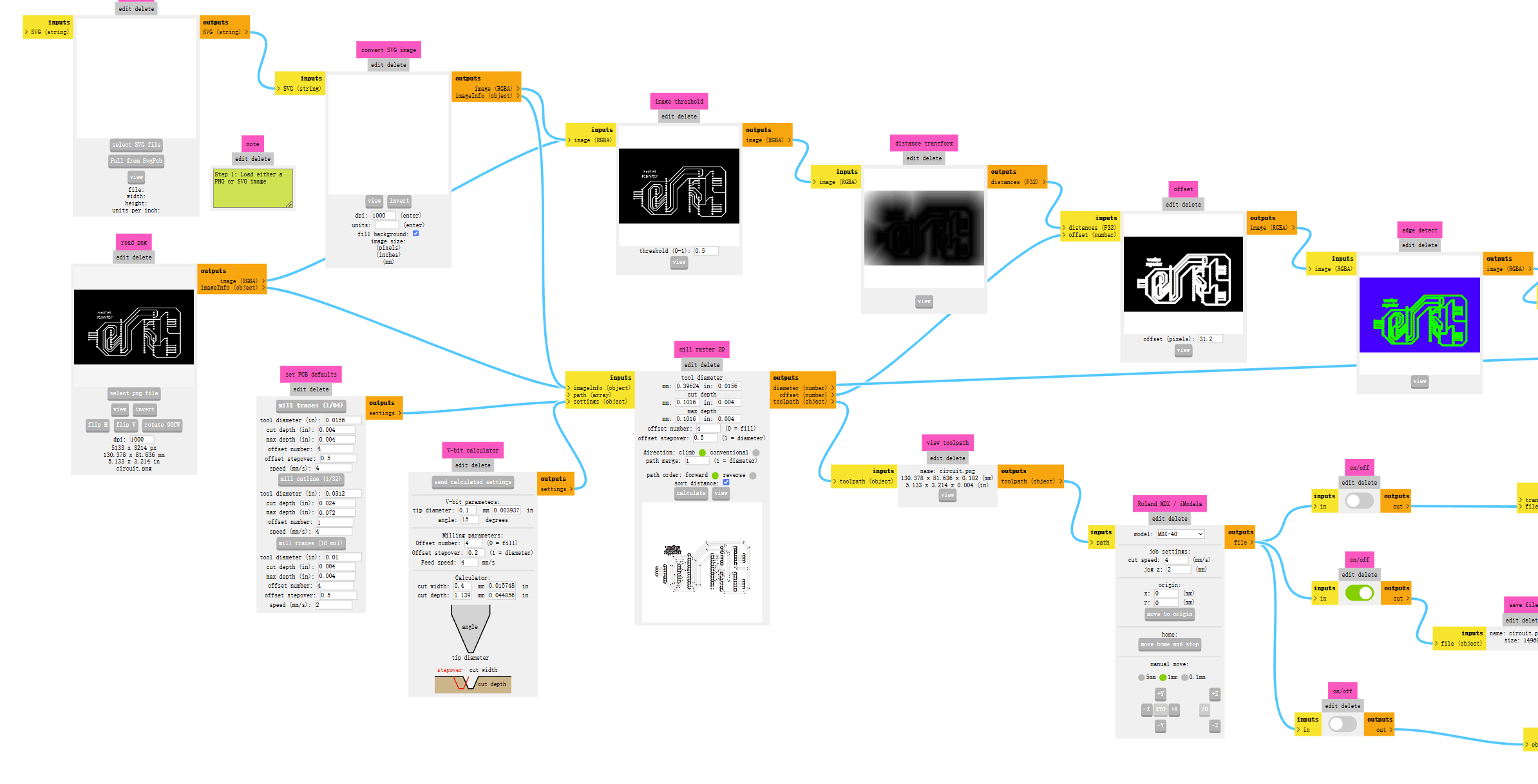
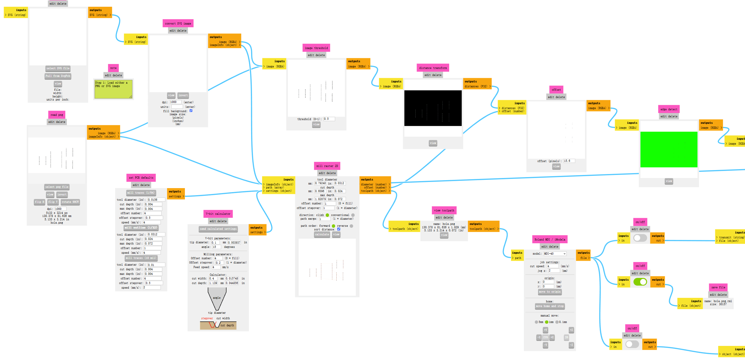
Mods Path Generation:
Mill traces:
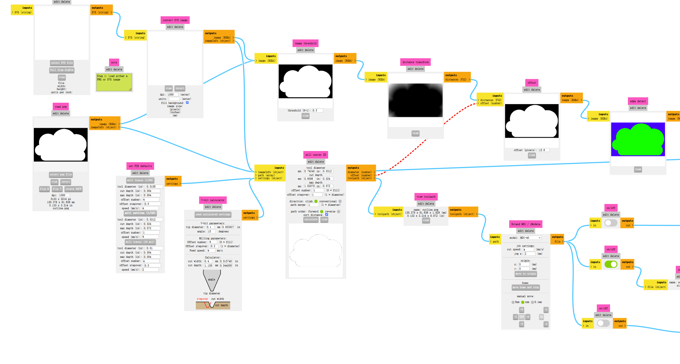
Mill outline:
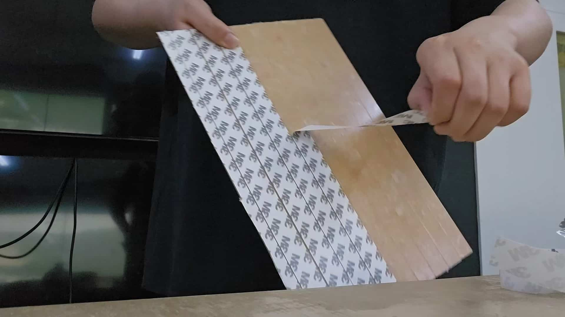
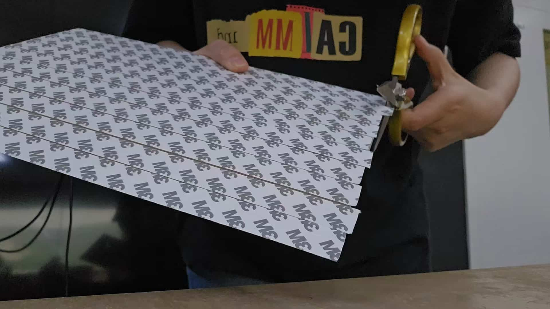
I placed a new copper-clad board, applied tape on the back, and cut off any excess tape. I positioned the board at an angle and pressed it flat, trying to squeeze out as much air as possible.
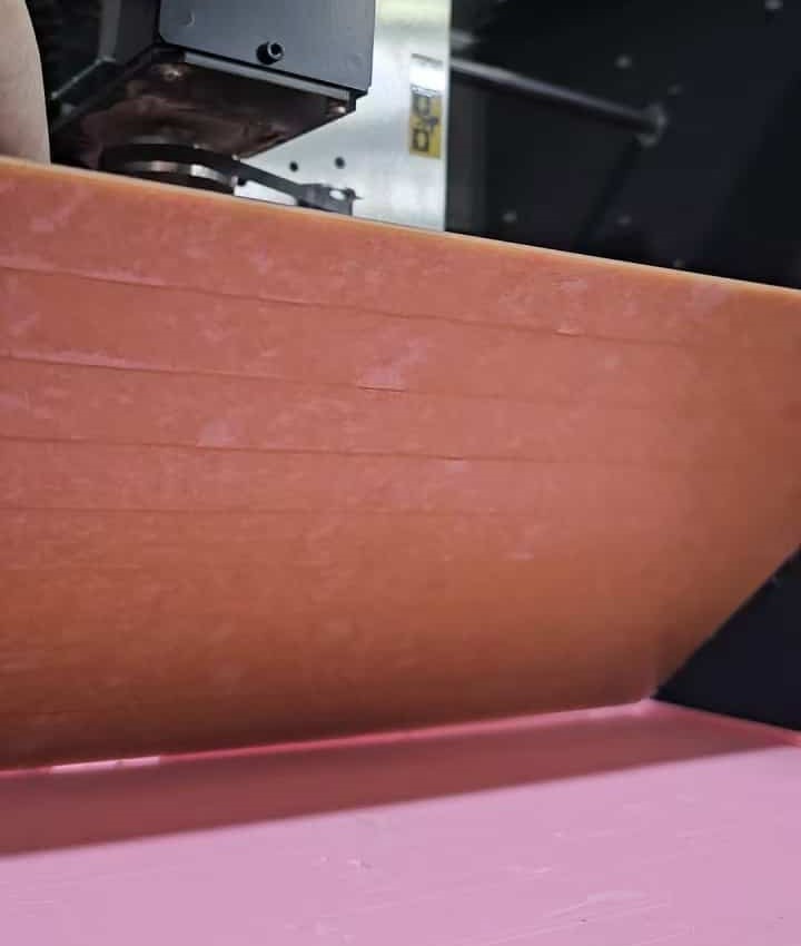
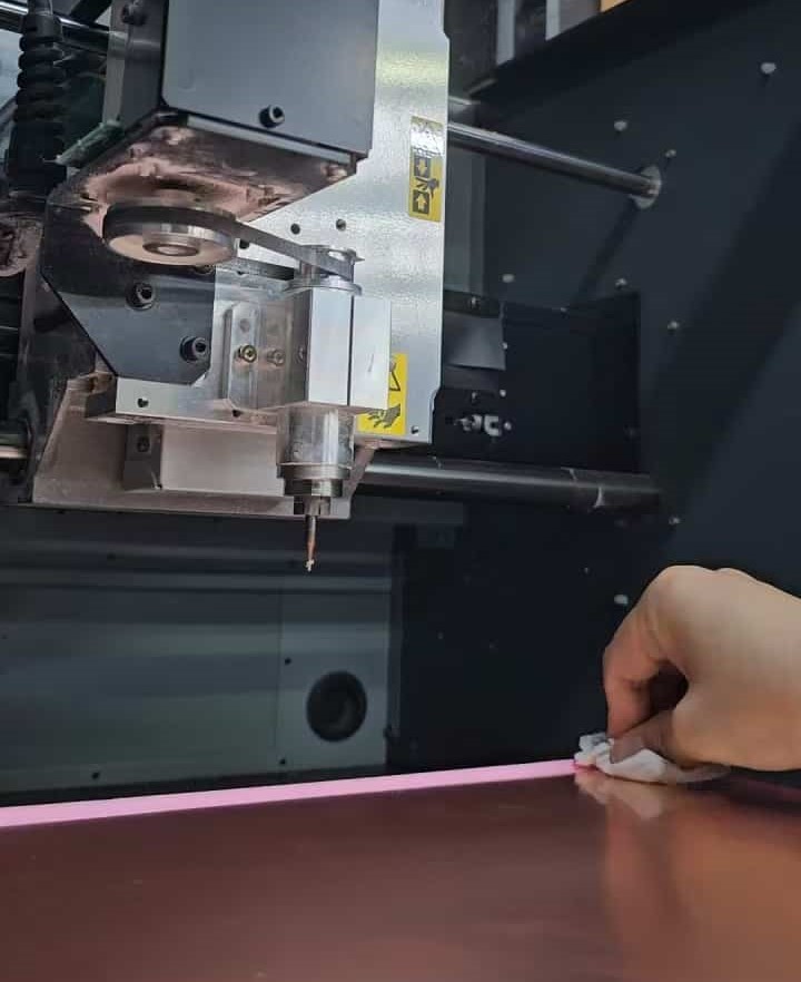
In VPanel, I adjusted the RPM to 10,000 and set the zero point for the Z-axis. To make the weather reporter look better, I installed a new milling cutter to perform the milling process.
Using tweezers, I gently pried up the edges of the board and then removed it carefully to avoid damaging it from a single direction. I cleaned the double-sided tape from the back, and the result was really nice!
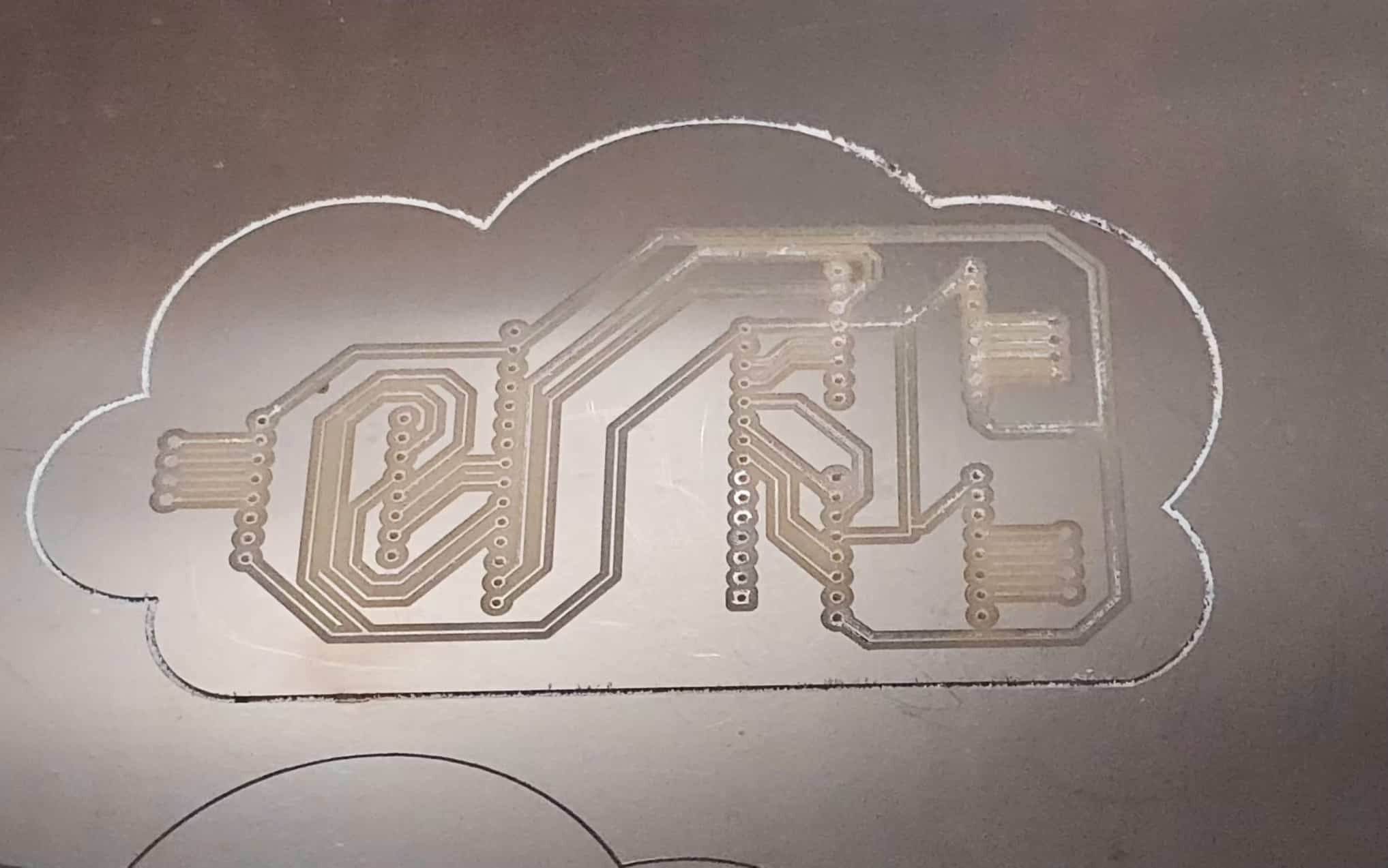
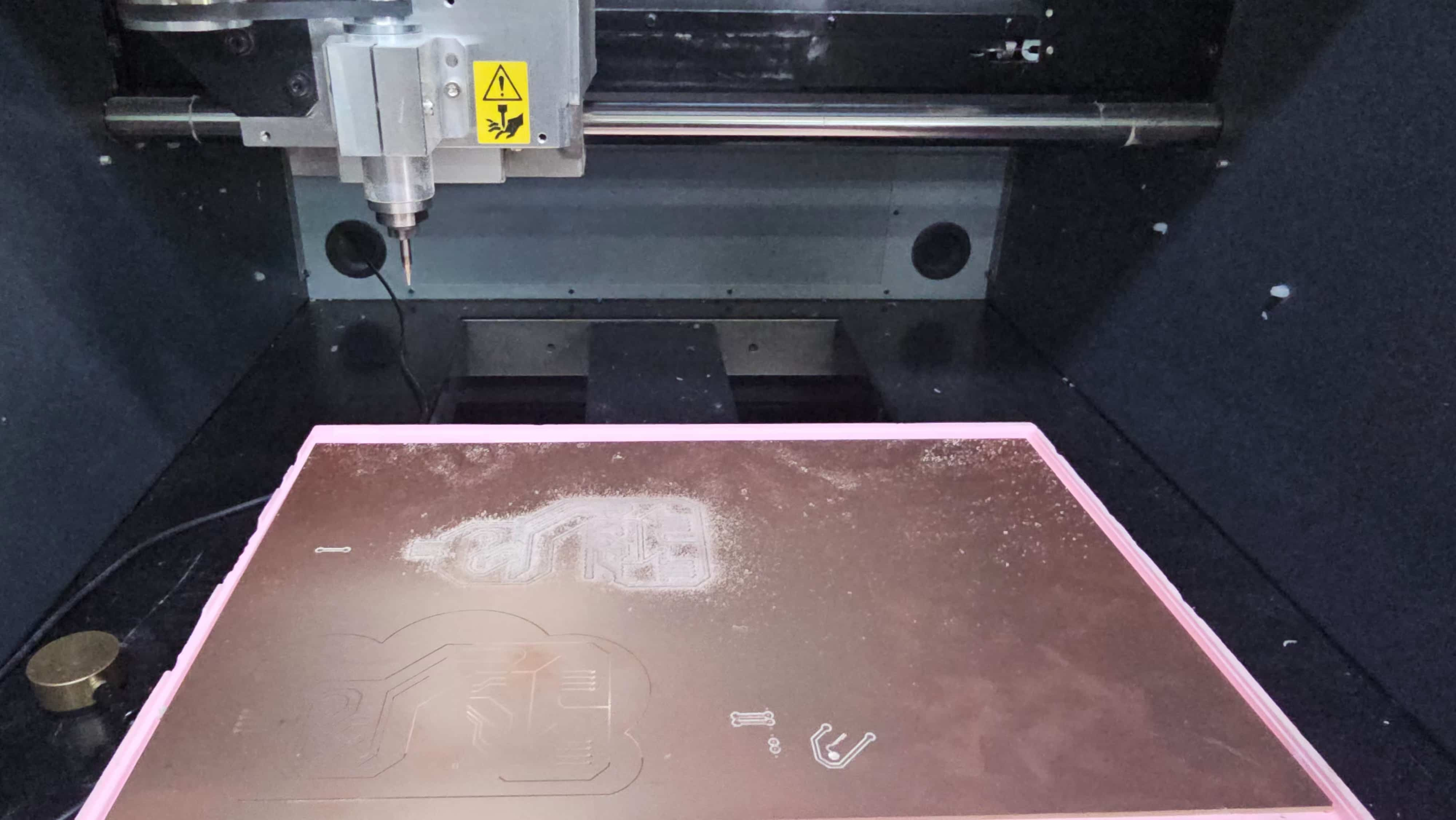
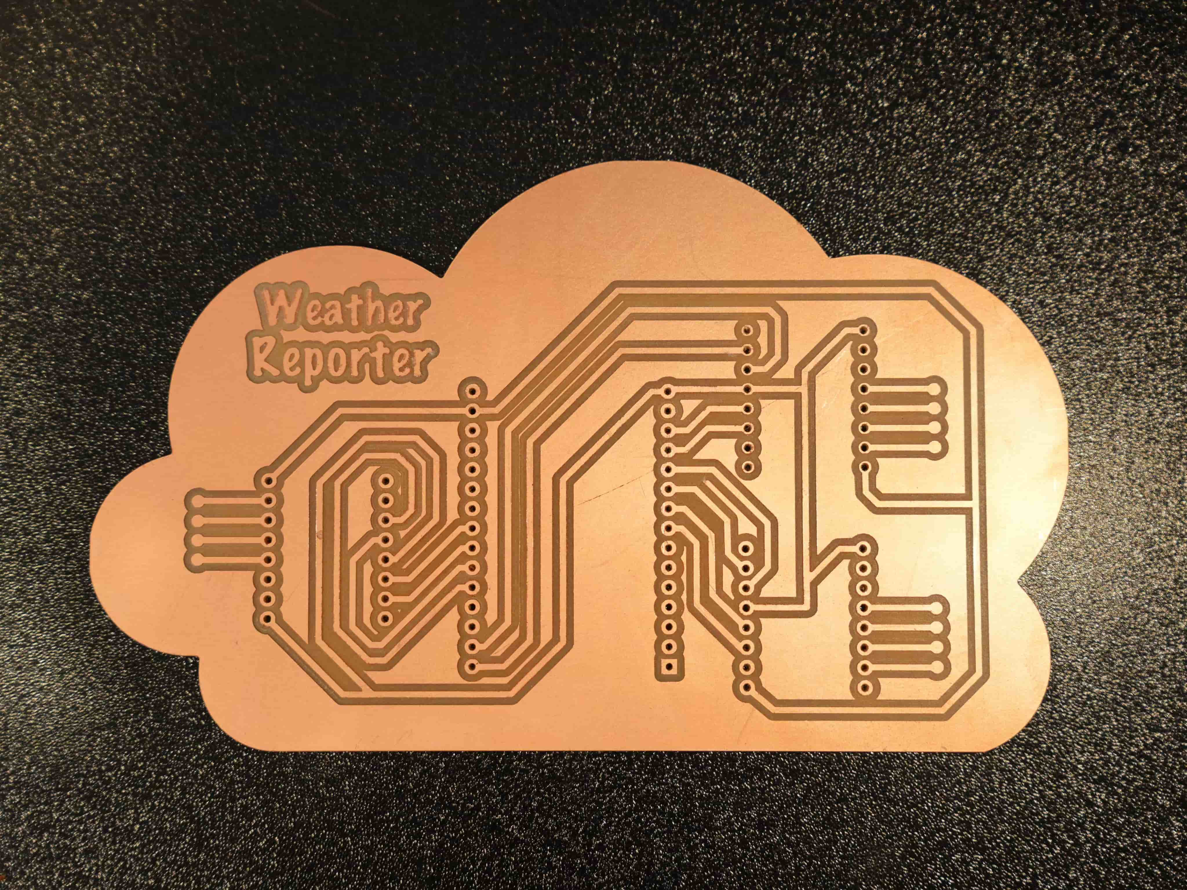
Prepare the following materials
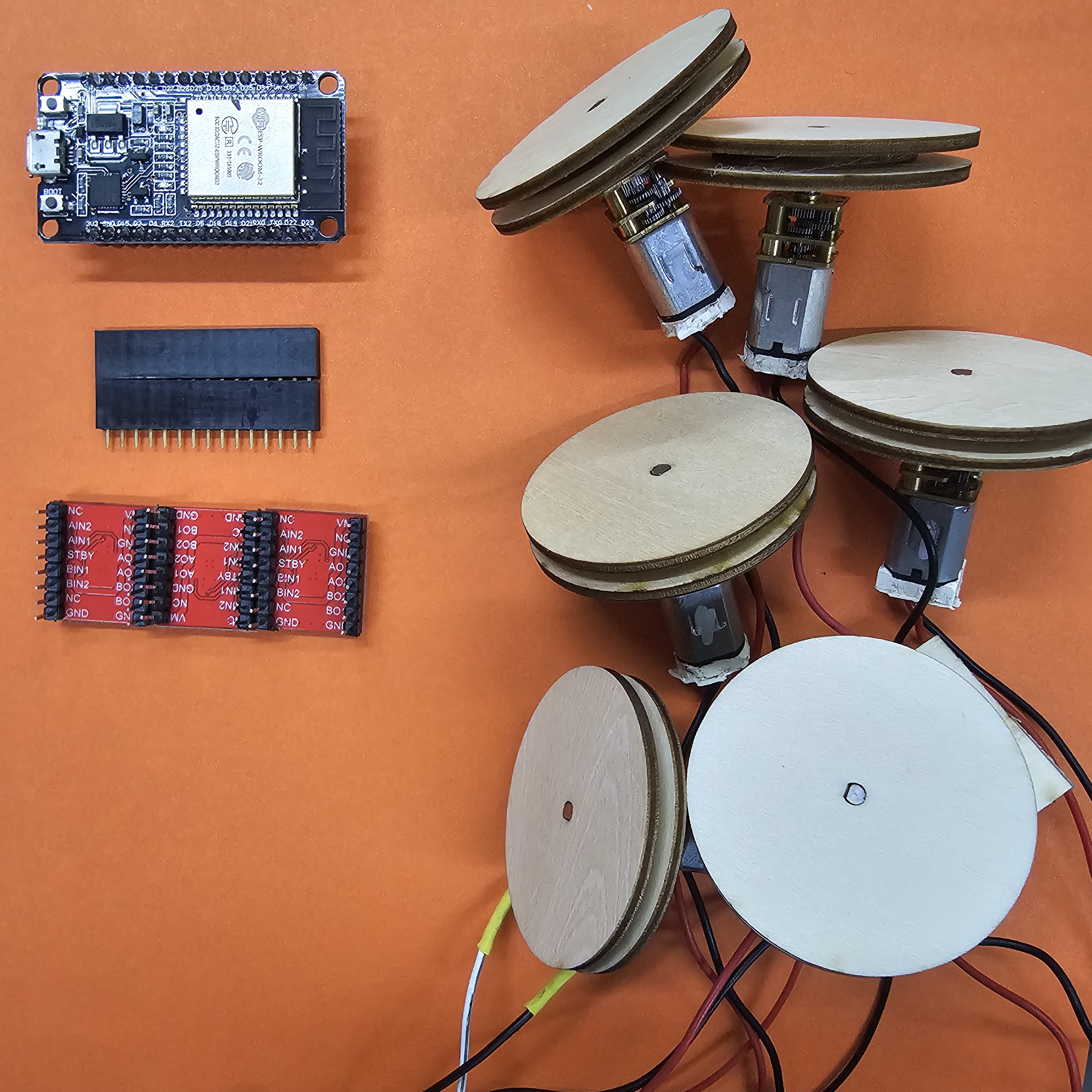
| Materials | quantity | cost(RMB) |
|---|---|---|
| ESP32*1 | 1 | 20.99 |
| DRV8833 Motor Driver Board*3 | 3 | 17.94 |
| GA12-N20 Gear Motors*6 | 6 | 47.94 |
| Single Row Female Header Pins*2 | 2 | 0.5 |
| Silicone Wires*1 | 1 | 3 |
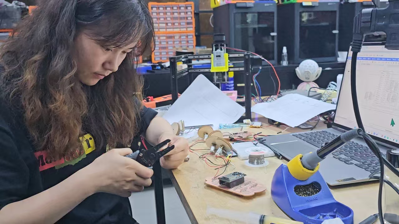
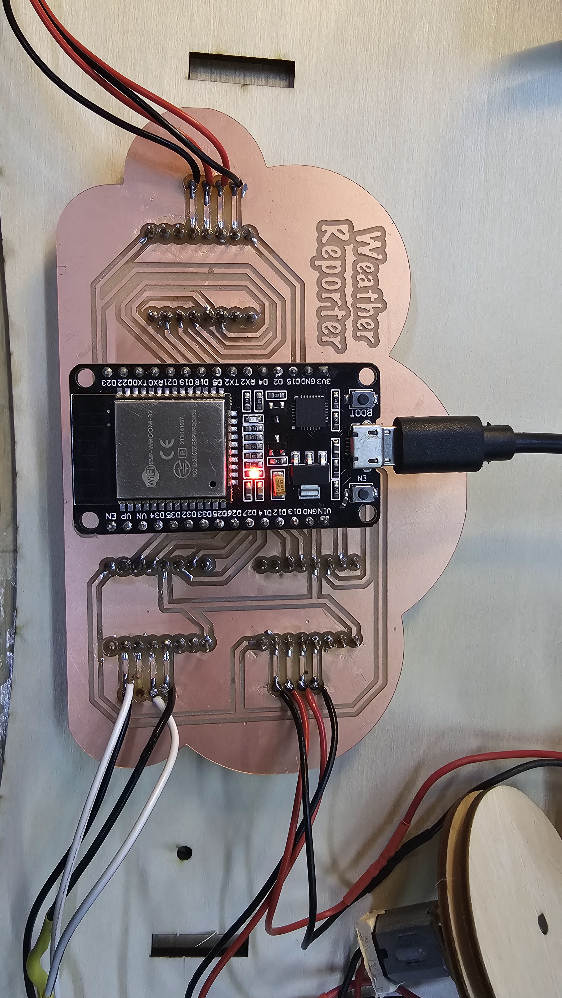
Use wire strippers to remove the outer silicone layer from the wires. Apply a little flux paste to the soldering points to help the solder wire connect better to the pads. When soldering the Motor Driver Board, make sure to check the orientation — if reversed, it won't work!
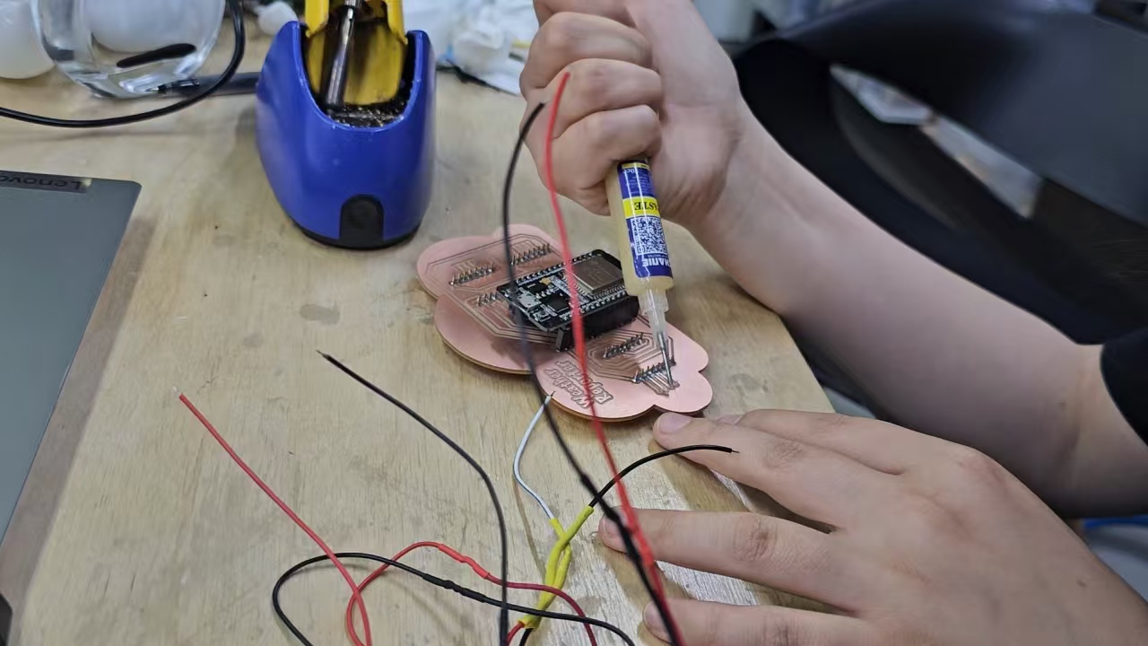
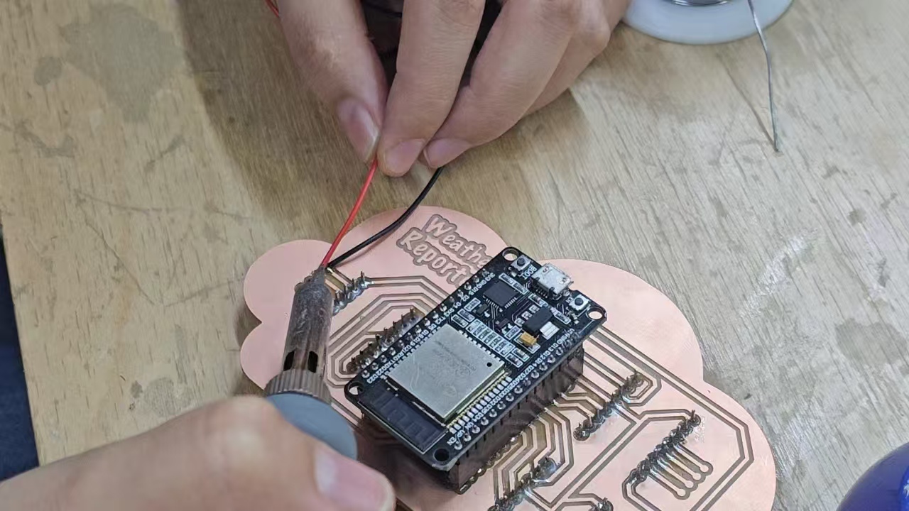
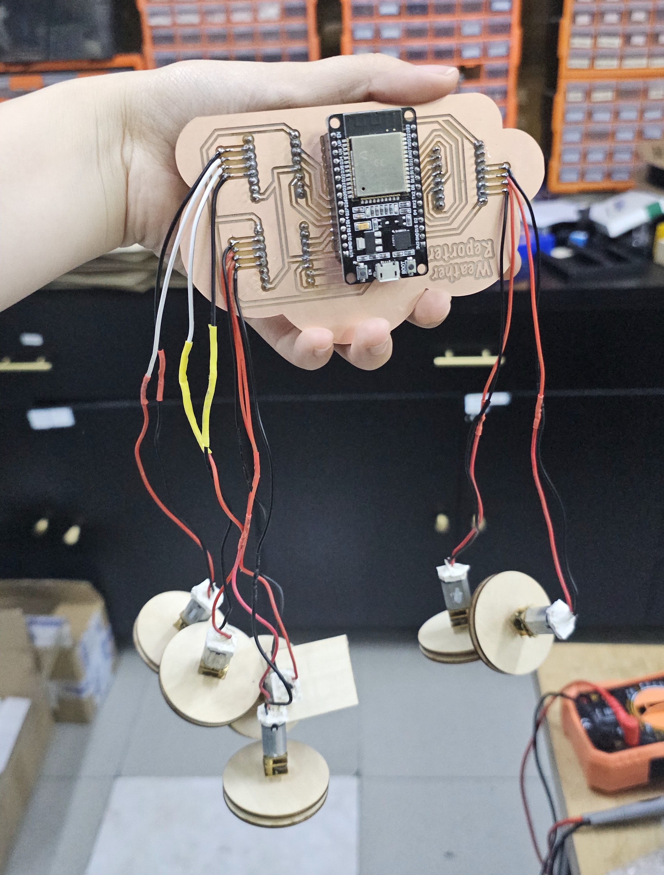
Here’s a look at the soldering results:
Programming
This project mainly uses Wi-Fi to retrieve weather information and controls the activation and deactivation of a set of motors based on the weather conditions. Below is a detailed explanation of each part of the code:
Motor Control Functions: The motor control section uses GPIO pins for six motors and controls their activation via PWM signals.
First, use a breadboard for testing to avoid wasting time if the code doesn’t work later.
The rest of the assembly tests the motors, which then move the corresponding weather icon upward based on the weather code.
Merge all the code
Bill of Materials
| Materials | quantity | cost(RMB) |
|---|---|---|
| 40x60mm Basswood | 1 | 23 |
| 3D Printing Filament | 1 | 10 |
| FR1 Copper Clad PCB*1 | 1 | 3.8 |
| ESP32*1 | 1 | 20.99 |
| DRV8833 Motor Driver Board*3 | 3 | 17.94 |
| GA12-N20 Gear Motors*6 | 6 | 47.94 |
| Single Row Female Header Pins*2 | 2 | 0.5 |
| Silicone Wires*1 | 1 | 3 |