Mechanical Design, Machine Design
[Hero shot]
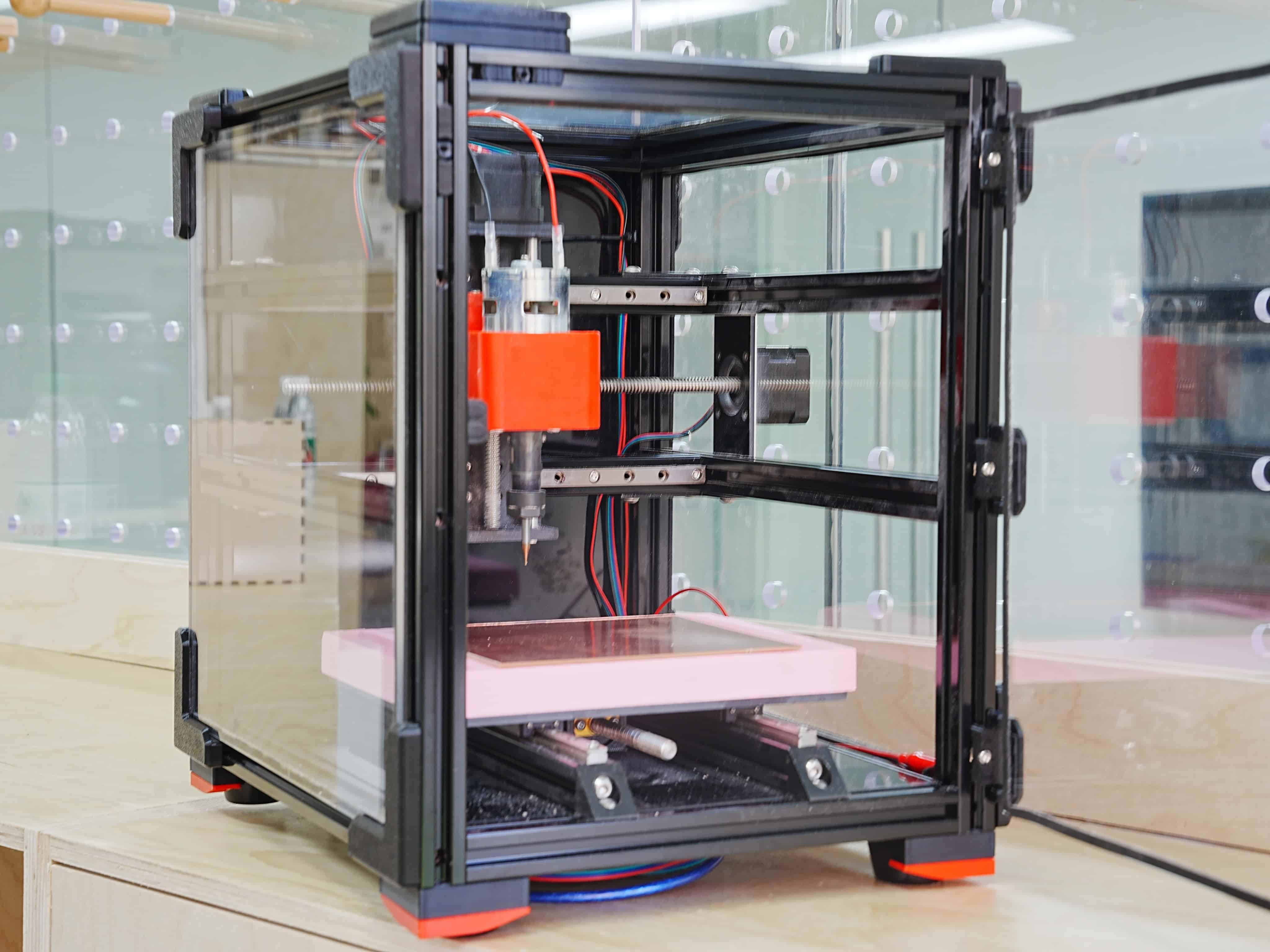
1.1 Assignments of the Week
Mechanical Design (part 1 of 2)- Group assignment:
Design a machine that includes mechanism + actuation + automation + application
Build the mechanical parts and operate it manually
Document the group project
- Individual assignment:
Document your individual contribution
- Group assignment:
Actuate and automate your machine
Document the group project
- Individual assignment:
Document your individual contribution
Here's our production process and final demonstration:
1.2 Design and Planning:
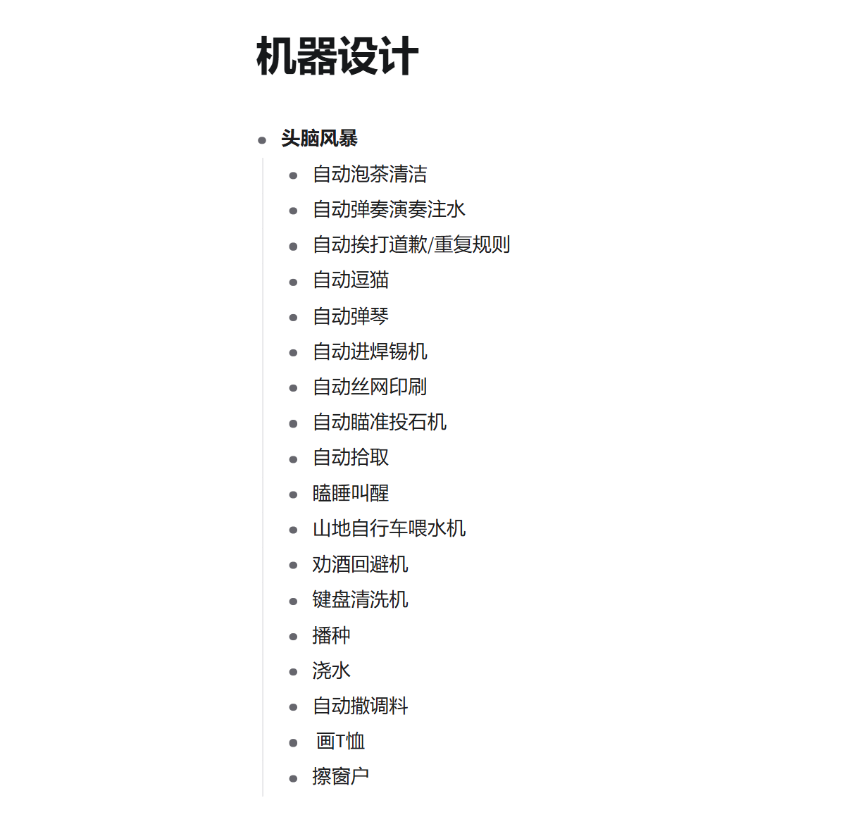
We brainstormed a lot of ideas, including an automatic T-shirt printing robot, screen printing, and more. Eventually, we decided on a 3-axis CNC machine because our lab currently needs a small CNC for educational purposes. It needs to be compact, simple, and portable, making it suitable for teaching middle and high school students. So, we decided to build this 3-axis CNC.
The CNC machine is mainly intended for engraving on circuit boards and wood, with a 150x150 mm engraving platform.
Division of Responsibilities:1.3 Materials Preparation
1.4 Mechanical Design
Frame Structure - Primarily constructed with aluminum profiles and 3D-printed parts.
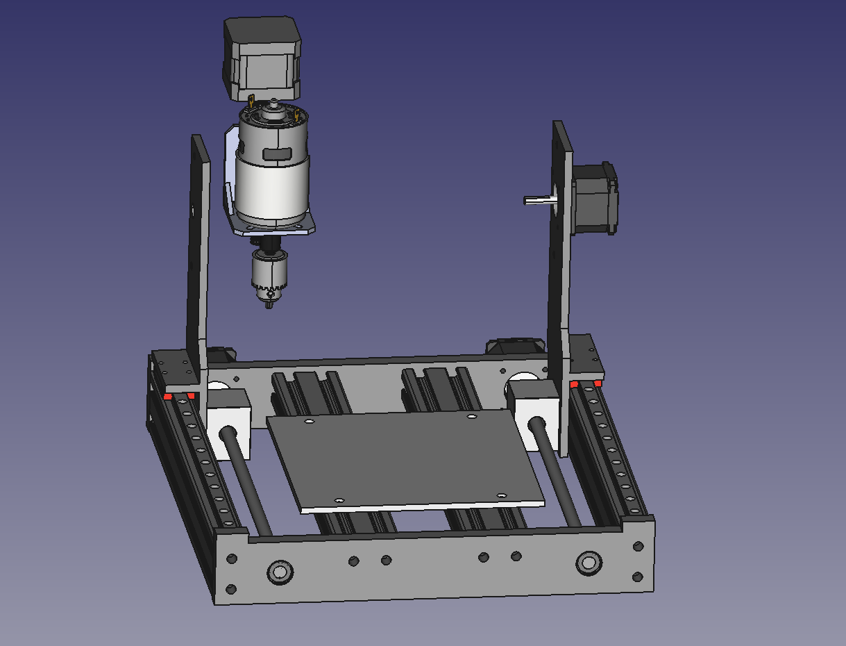
Since we aim to make a compact machine, a moving Y-axis setup would increase the distance required, so we adapted a gantry-style movement instead.
The base is framed with aluminum profiles on all four sides, enclosed by 3D-printed parts that allow space for the lead screws, aluminum profile platform, bearings, etc. To maximize the internal workspace, we positioned the motor externally. The spindle section uses pre-made injection-molded parts, connected to the gantry by custom 3D-printed components.
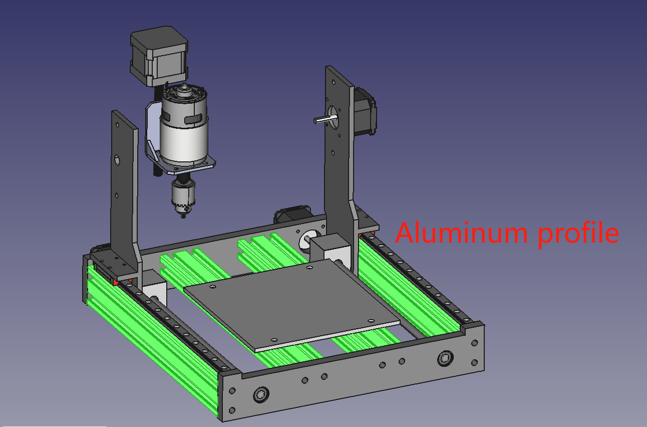
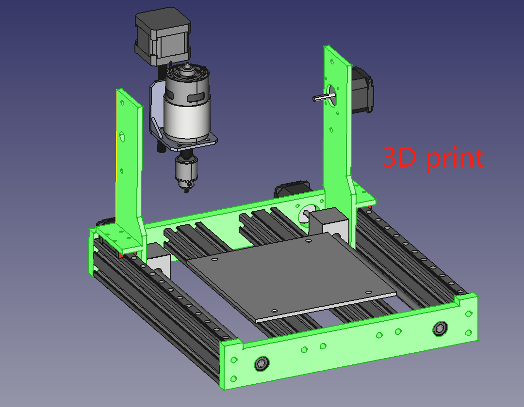
For further details, please refer to Siyuan Fan's documentation.
1.5 Electronic Control
We use the Makerbase MKS LS ESP32 PRO control board.
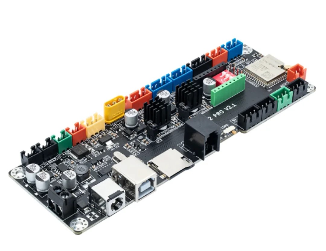
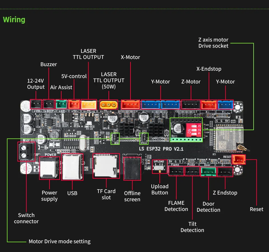
Advantages
Disadvantages
Connect stepper drivers and motors, configure parameters, and set up software. For detailed steps, refer to Ziyi Zhu's link .
Conduct tests and debugging: Test each stepper motor's smooth movement, axial alignment, and rotational accuracy. Perform individual tests.
Testing a single motor:
Testing two motor:
Everything seems fine...
1.6 Assembly - My Part
This week, I was mainly responsible for the assembly.
The project was quite complex, so we planned ahead and purchased the materials in advance. However, we still encountered several issues, such as receiving the wrong lead screws and delayed arrival of the couplings.
I've already listed the material list above, and we started installing from the bottom.
The installation of the bottom frame went smoothly until we reached the lead screws. We had originally bought three, but the seller only sent two, and one of them was too short. With time running out, we decided to repurpose a lead screw from an idle CNC machine in the lab, but we found that the lead screws had different pitches. In the end, we had no choice but to use the incorrect short lead screw for the lower motor.
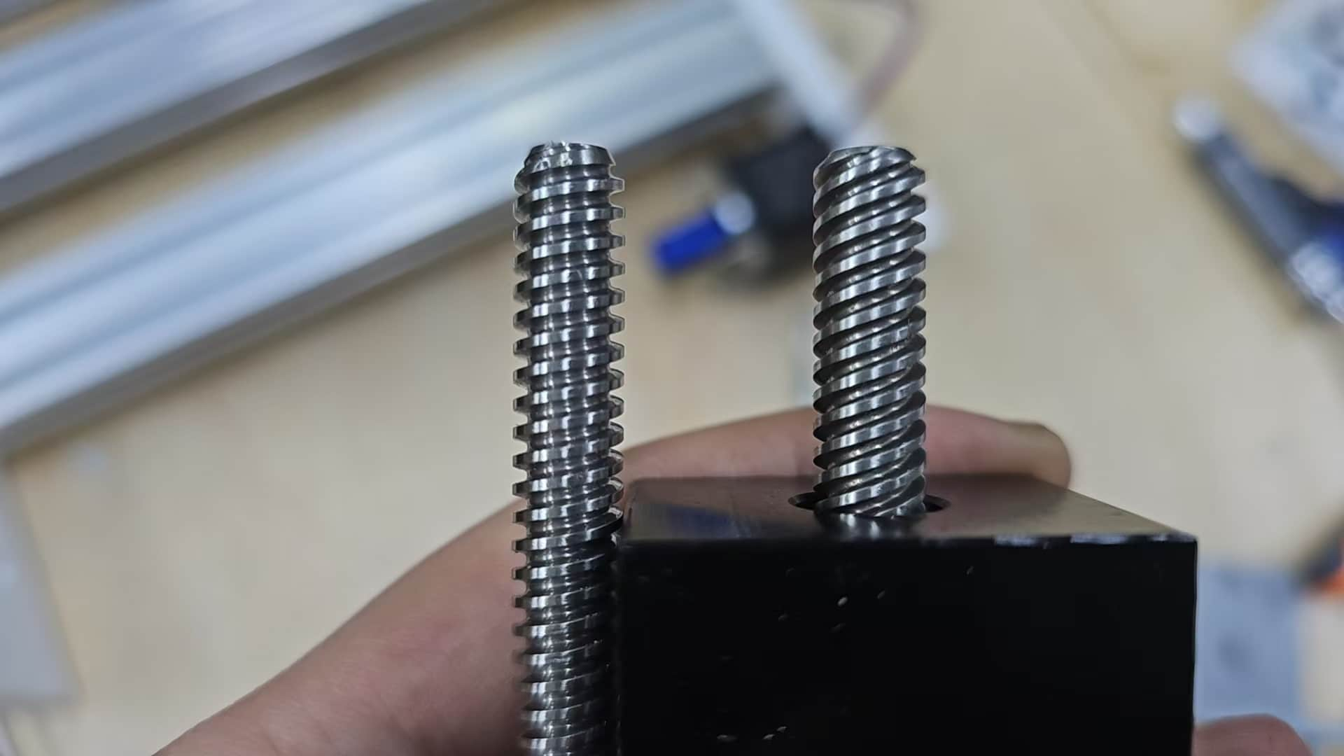
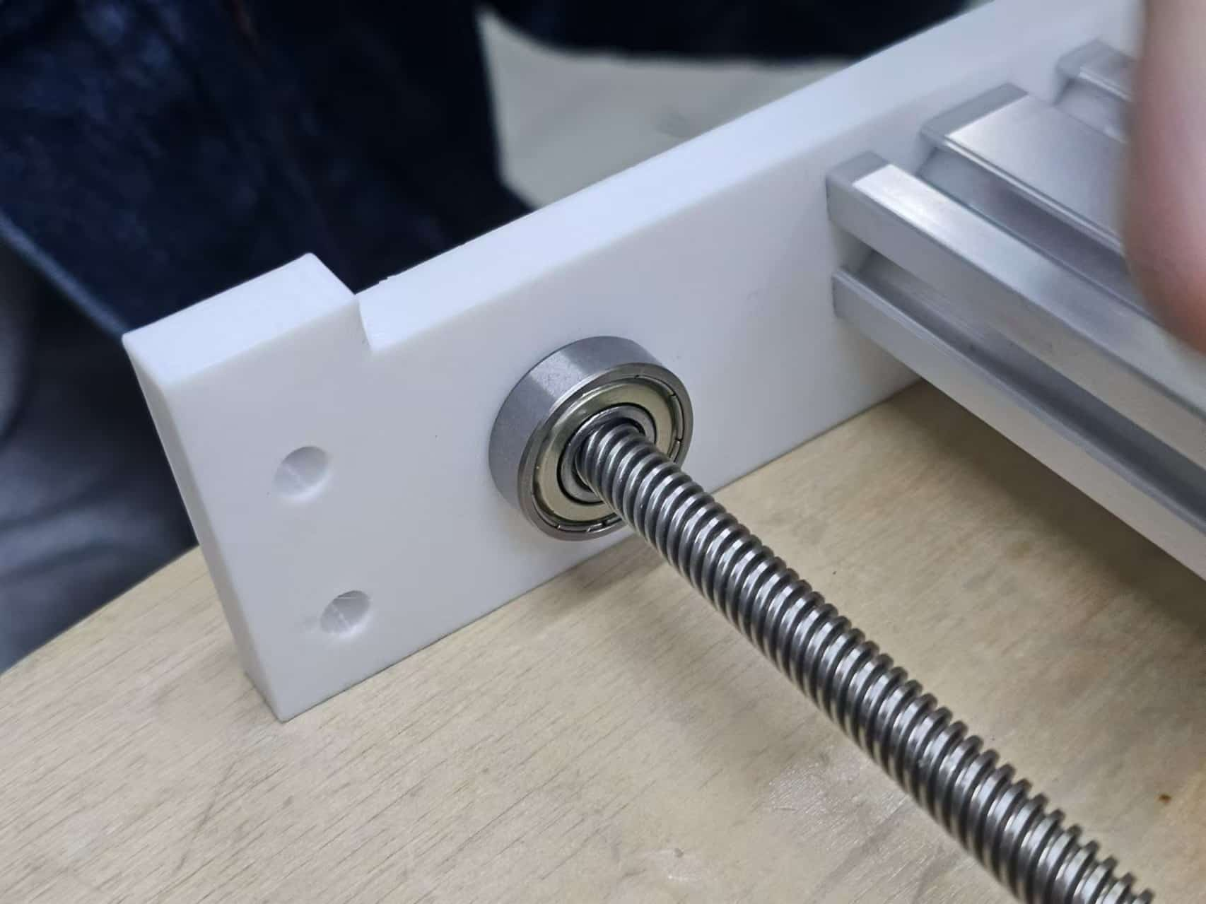
It was a bit too short, so we tried using a bearing to secure it in the middle and shortened the lead screw a little to fit the coupling. Then we fixed the bearing with hot glue - it seemed to work! However, after testing, the lead screw wobbled a lot.
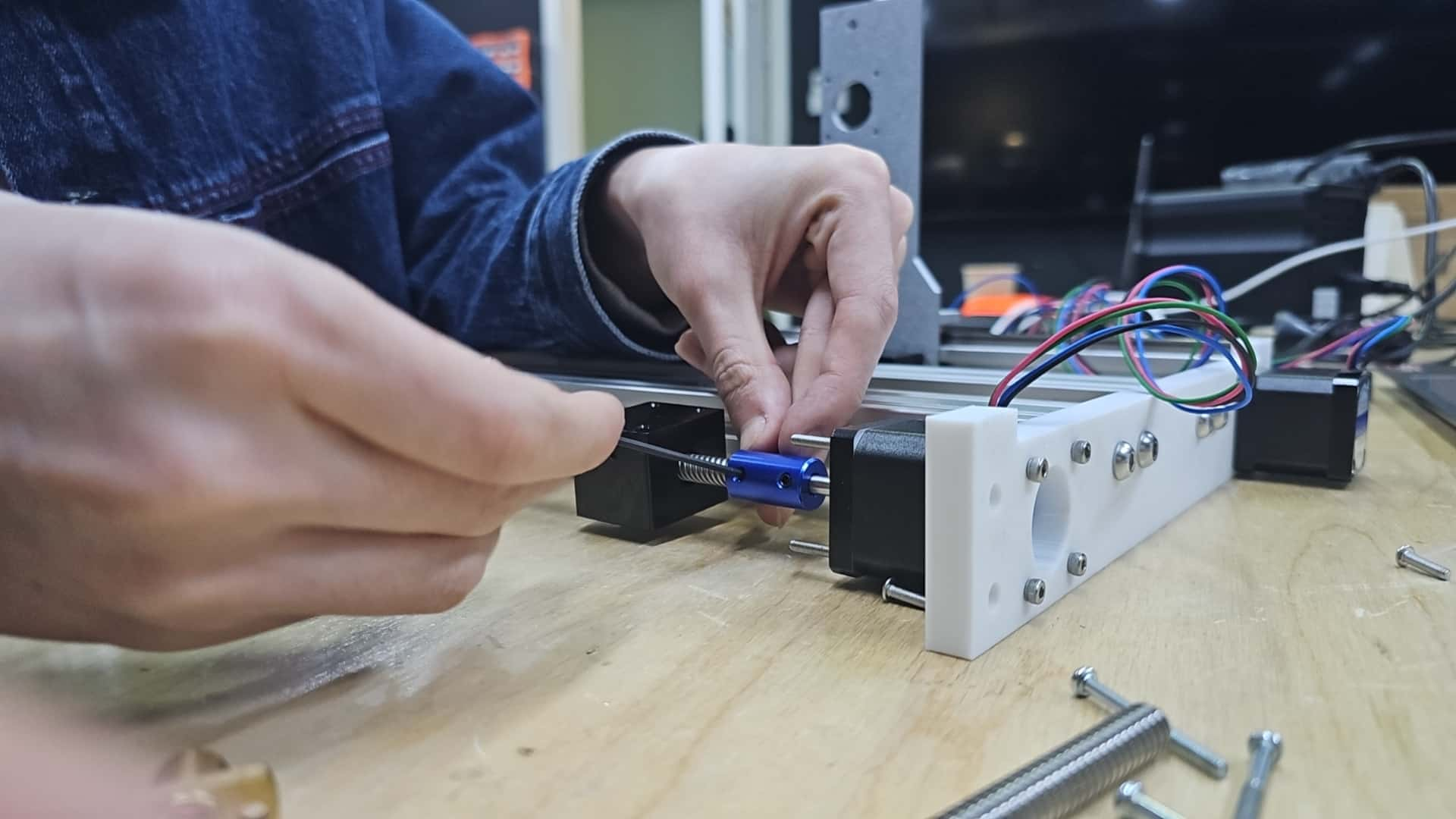
After thinking for a while, We remembered that the lab had some double-pass hexagonal copper pillars. So, I found four M3*30 copper pillars, which helped alleviate the issue of the lead screw being too short.
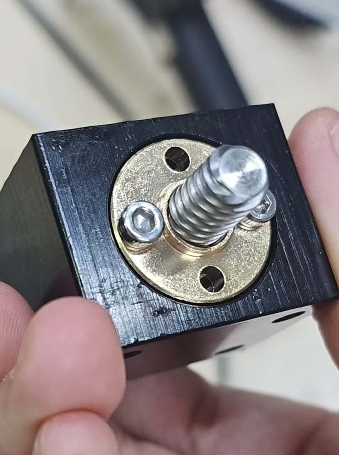
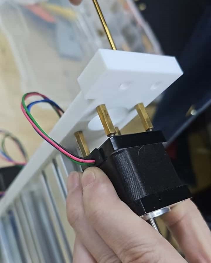
With the main problem resolved, we continued installing the rest of the components, and the assembly was finally completed!
For more assembly process, please watch the video at the beginning
Hero Shot:
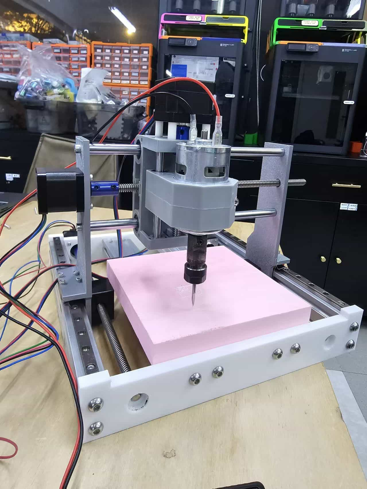
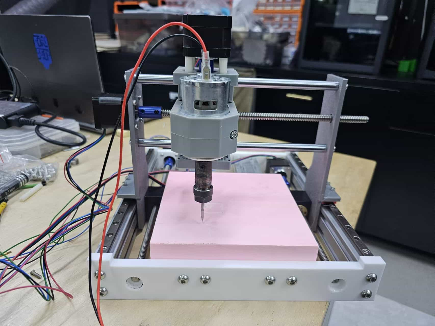
- Structure and Stability: Ensure every connection point in the frame is securely fastened and aligned to minimize vibration. Choose durable materials and stable support structures to prevent misalignment or deformation during machining.
- Motor Installation: Securely fasten the motor to avoid loosening. Ensure the motor is aligned with the transmission mechanism to prevent additional stress during operation.
- Cable Management: Organize cables for the motor, limit switches, and other components to avoid wear or tangling during operation. Use cable ties or clips to keep cables tidy and reduce interference and friction.
- Lubrication and Cleaning: Apply a suitable amount of lubricant to the lead screws and guide rails to ensure smooth movement. Regularly clean the workspace to help extend the CNC’s lifespan and improve machining results.
Here are some assembly tips:
1.7 Milling Test
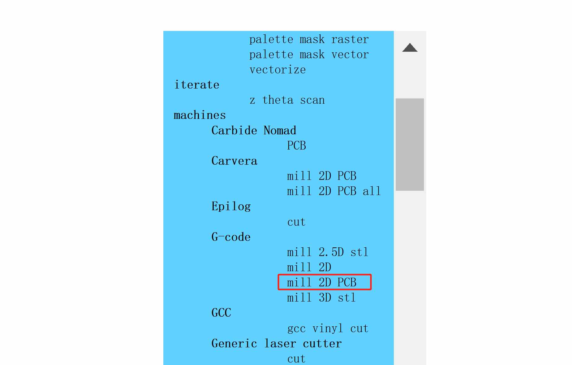
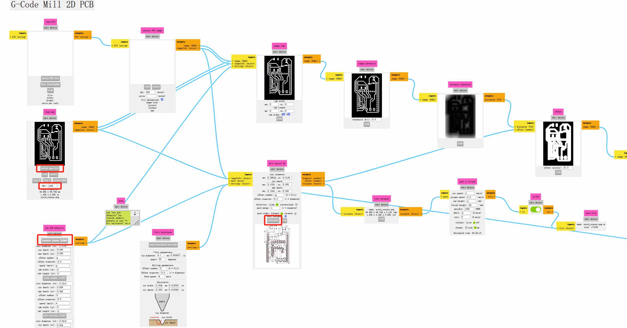
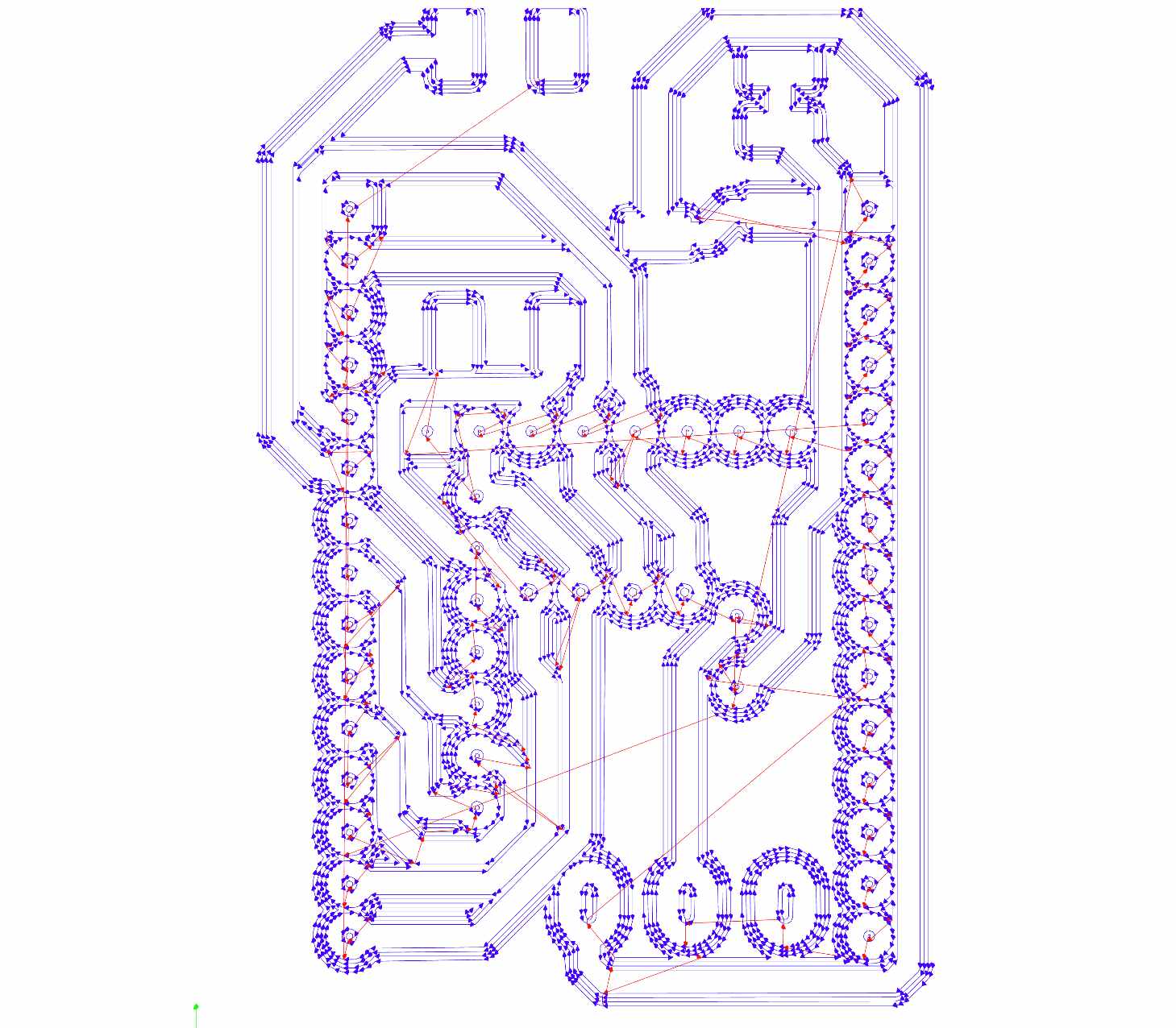
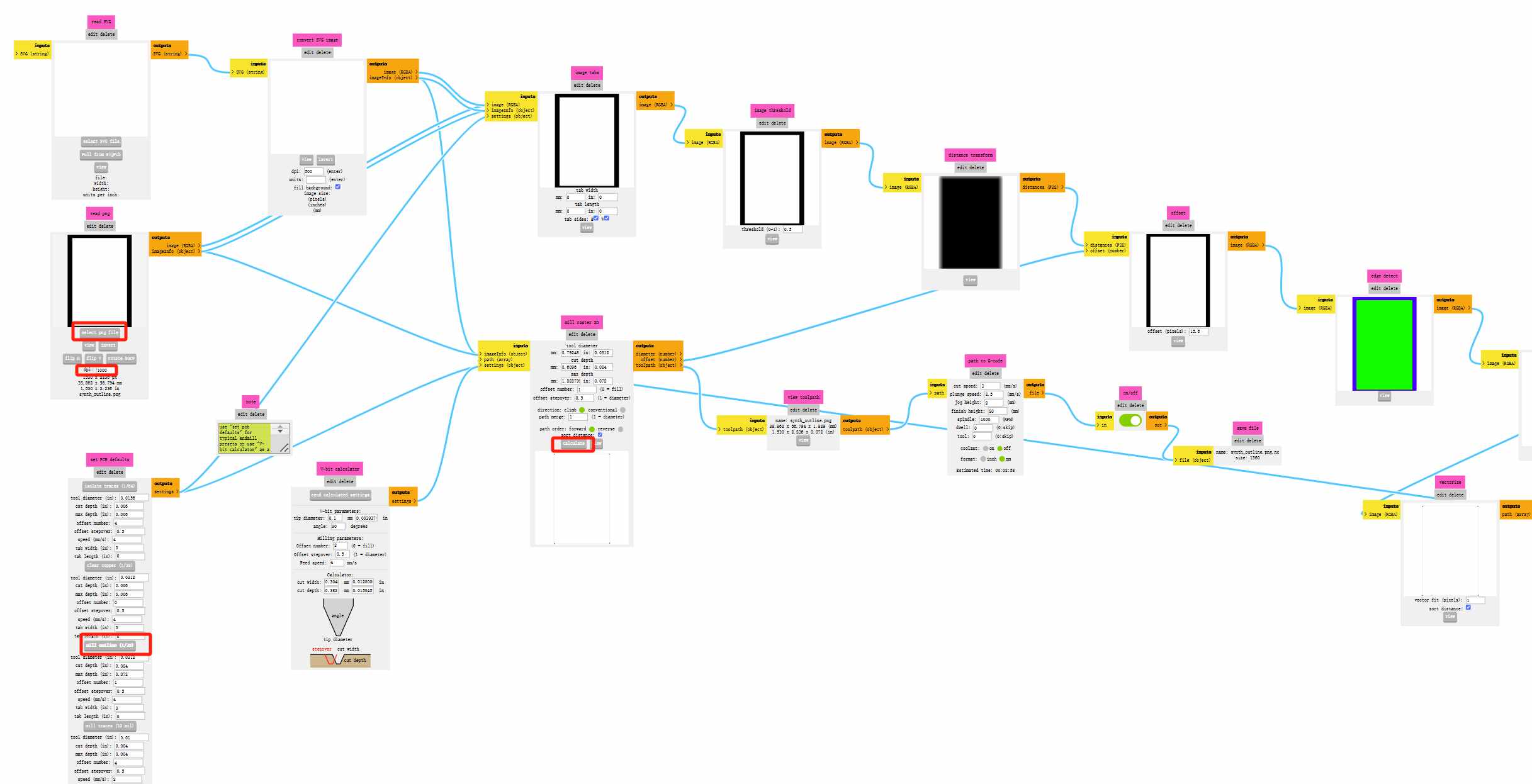
We used Mods to generate the toolpaths, which is a bit different from the Roland workflow. Select mill 2D PCB, import the PNG file, and as before, set the resolution to 1000. For internal circuits, select traces (1/64), and for external outlines and vias, select outline (1/32). Click calculate! to export the G-code.
( This part was added later because the original model was lost. I used another PCB to explain the process of generating toolpaths and controlling the machine.)
traces:
outline:
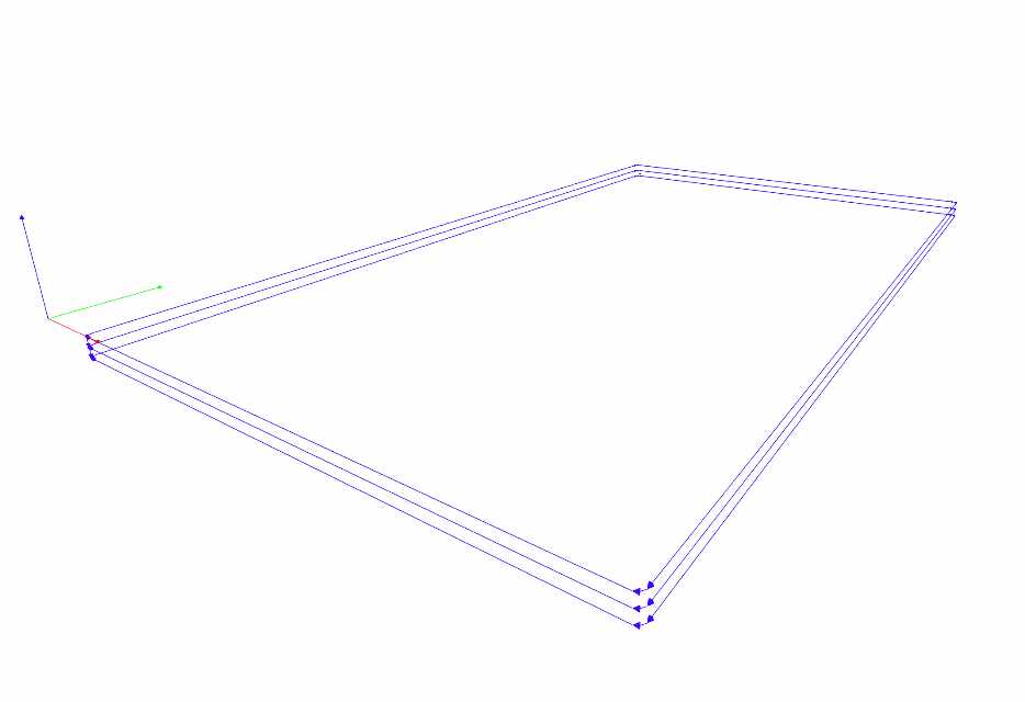
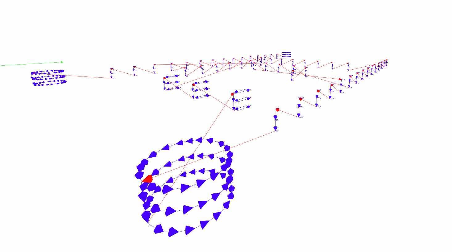
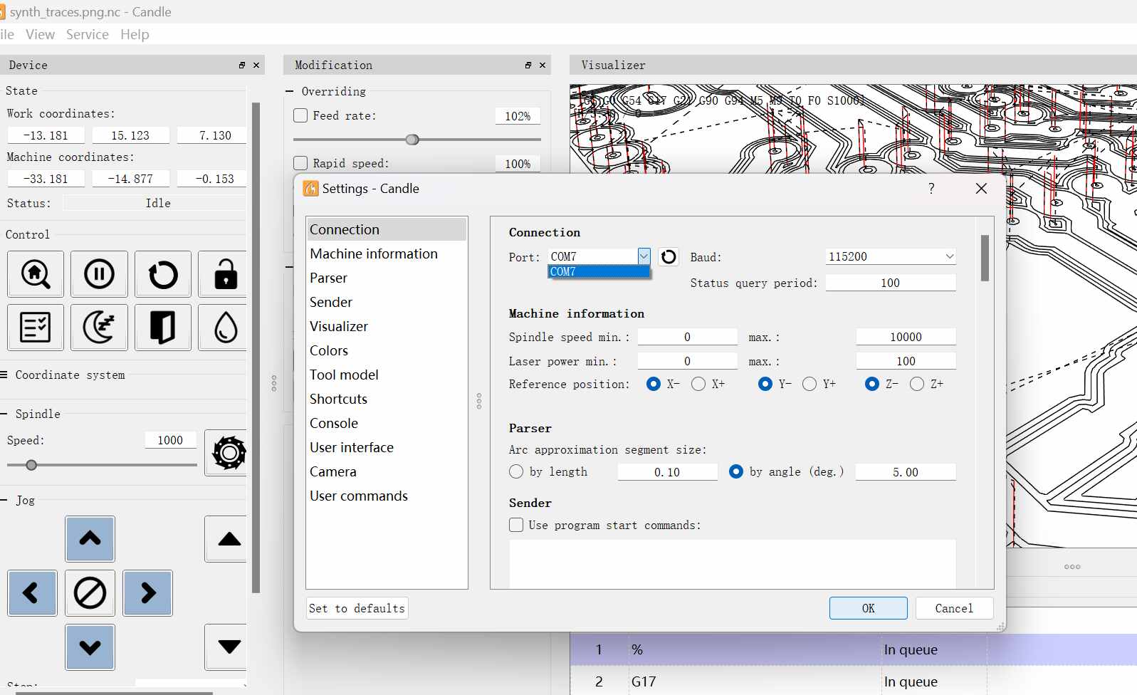
Open the generated file in Candle. Connect the computer to the machine, then in Candle, click Service and select Settings to ensure the correct serial port is selected.
Use the arrow keys to move the drill bit and position the XYZ to the origin. Click Reset to start cutting. If any issues arise during the process, you can click Abort to stop. Once the cutting begins, there’s a synchronized animation showing the milling progress, which is very intuitive!
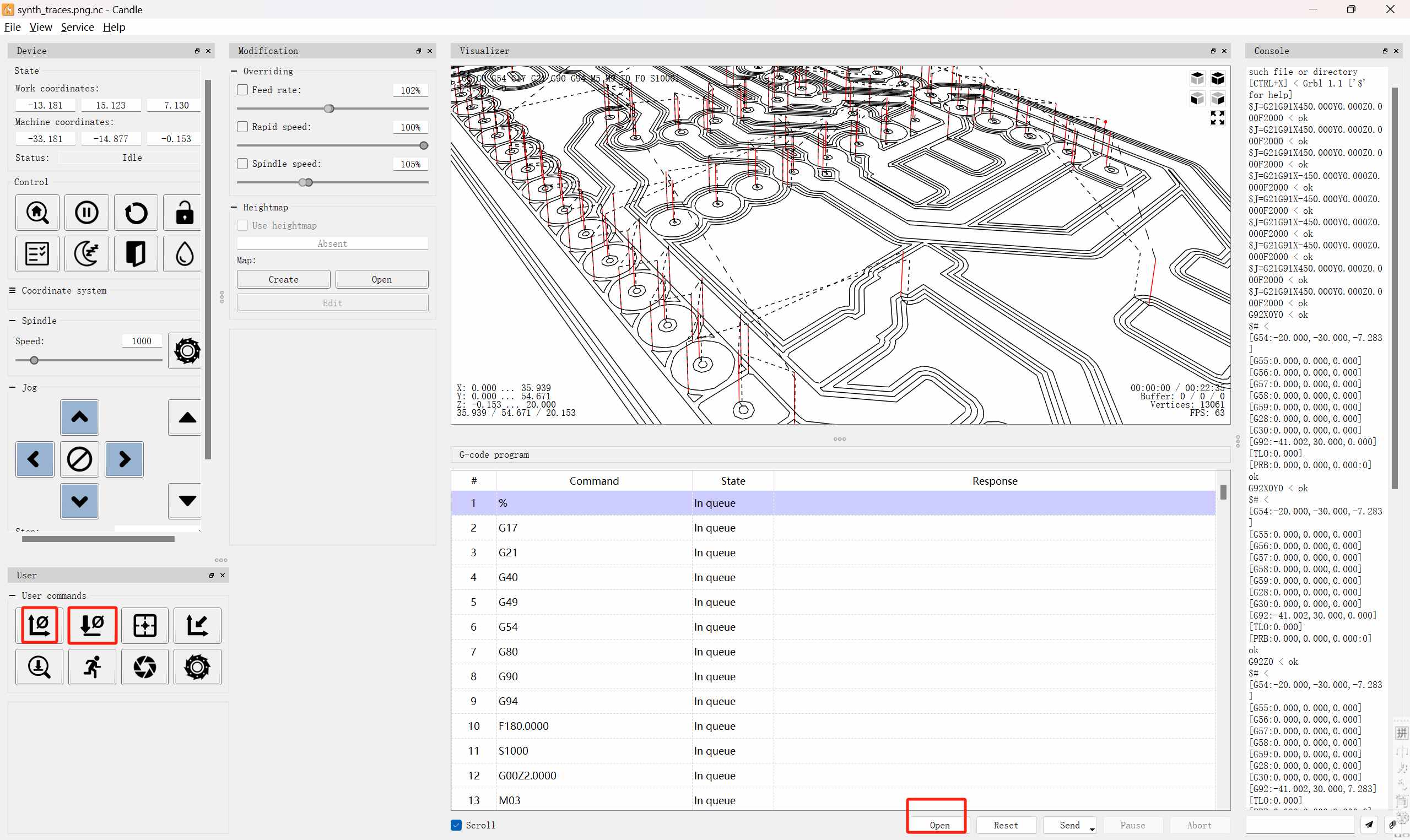
The machine milling process includes real-time tracking in Candle, as well as the subsequent machining of Delrin (captured in the only two clips filmed after completing the machine).
It works very well, it's really exciting! (Here we used a piece of wood for testing, and the instructor said to use PCB testing later, but the first version has been dismantled... We will show the new machine test later... Please look forward to it)
But there are still some areas for improvement
Four months later — 【QIAO-JIANG】 was born.
We underwent a major redesign and started over.

| No. | Materials | numbers |
|---|---|---|
| 1 | 2020B-230 Both Ends Tapped M6-20 Aluminum Profile | 6 |
| 2 | 2020B310 - Drilled - Both Ends Tapped M6-20 Aluminum Profile | 4 |
| 3 | 2020B 310 Both Ends Tapped M6-20 Aluminum Profile | 6 |
| 4 | 2020B-330 - Drilled | 4 |
| 5 | Triangular Connecting Block | 4 |
| 6 | Linear Rail | 4 |
| 7 | Lead Screw | 3 |
| 8 | Stepper Motor | 3 |
| 9 | 10mm Optical Axis | 2 |
| 10 | M6✖30 Optical Axis | 8 |
| 11 | 200W ER11 Spindle Motor (Speed 10000) | 1 |
| 12 | Lead Screw Adapter | 2 |
| 13 | 3D Printed Parts | Several |
| 14 | TMC2209 Driver Chip | 3 |
| 15 | Round Rubber Pads | 4 |
| 16 | CNC Machined Bakelite | 2 |
| 17 | GRBL Control Board | 1 |
| 18 | Alligator Clips | 2 |
| 19 | White Transparent Acrylic | 4 |
| 20 | Black Transparent Acrylic | 2 |
| 21 | Screws | Several |
- Some new changes:
- Solved the noise and vibration issue — we replaced the 795 motor with a professional 200W motor for the spindle.
- The cutting marks are now complete and beautiful — the original tool holder wasn't aligned properly.
- Added automatic tool calibration.
- Magnetic enclosure with removable doors on all four sides for easy cleaning and tool replacement.
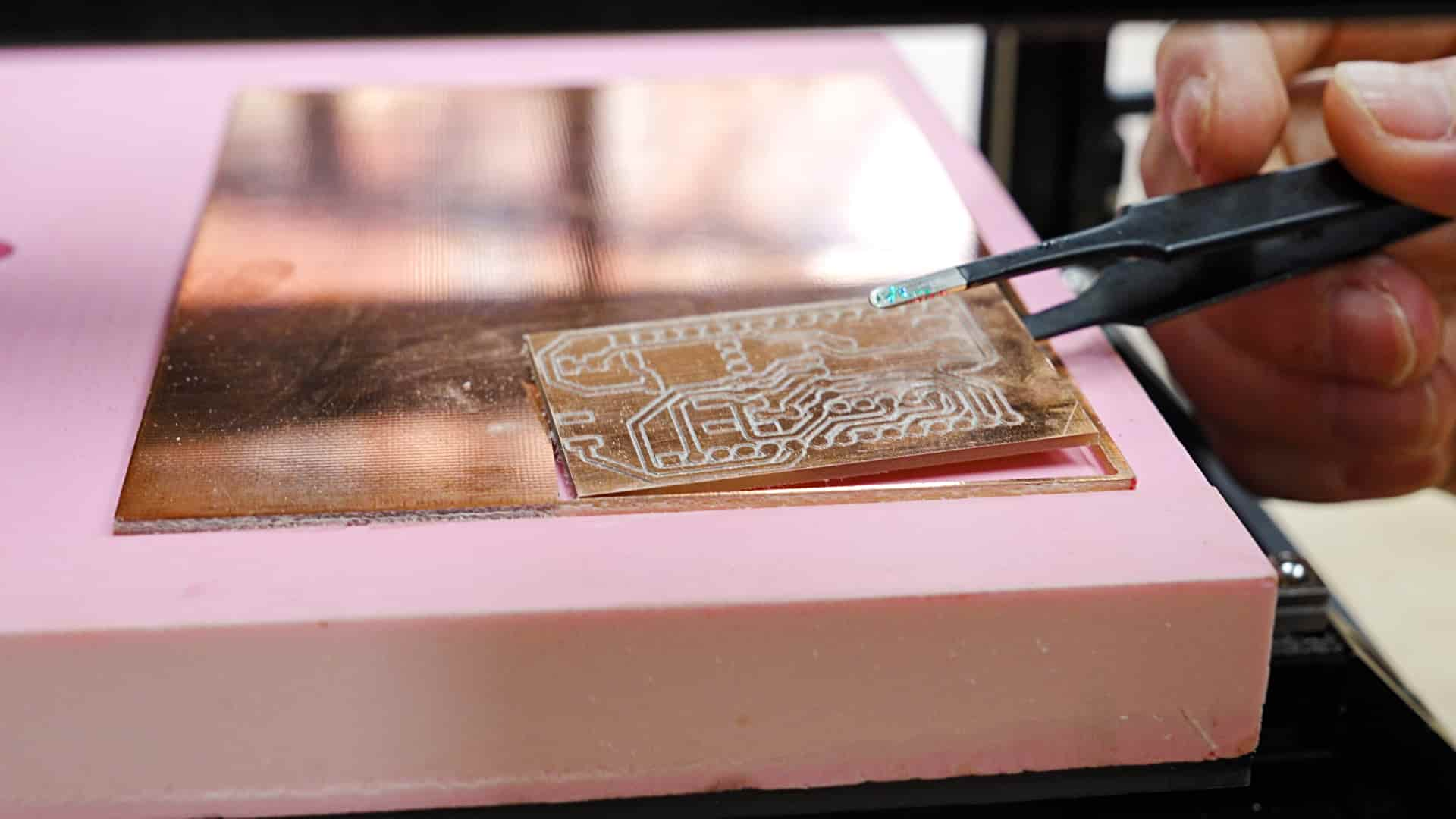
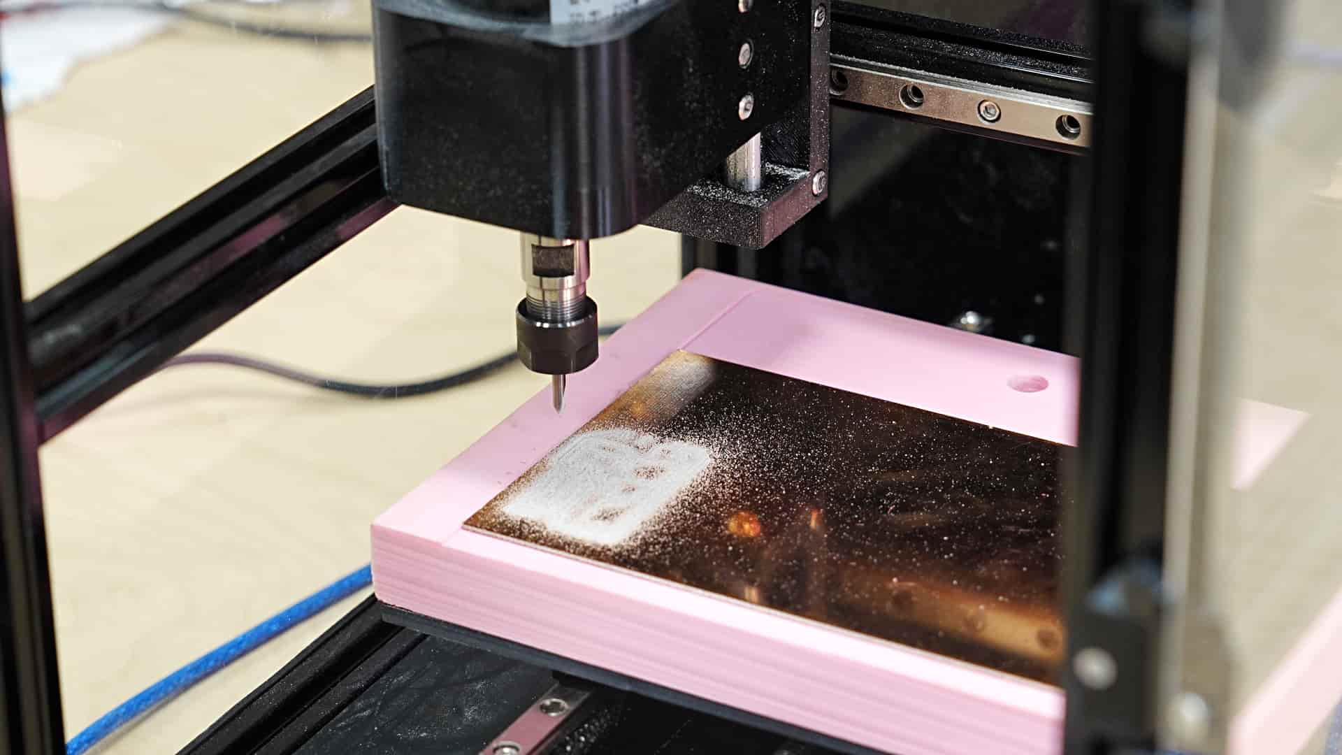
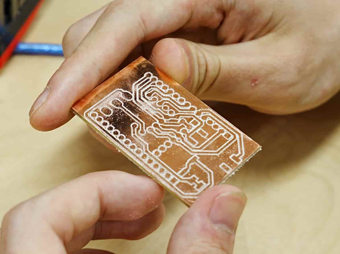
We tested it with a sound synthesizer PCB.As before, we used **Mods** to generate the toolpaths and **Candle** to control the machine.The cutting process is very stable
The PCB turned out beautifully! The precision of the cutting path is exceptional, and the overall finish is incredibly clean and sharp. After vacuuming, the surface is spotless, with every trace and detail perfectly visible. It's truly an outstanding piece of work!


This equipment is now sold commercially (18 units sold)