2. Computer-Aided Design
This week, I designed my final project using CAD.
Before utilizing CAD, I wanted to change my design a little. I’m changing the shape of the pot to be a cylinder so that I can design the pot to allow you to remove and attach each section easily by utilizing tabs and on each piece that becomes secure once you twist it on. Also, I changed the orders of the layers so that the elctrical compartment is in the middle so that the electrical components don’t need to move through the water compartmnet to get to the soil.

Fusion 360
Making General Outline
The software I chose to design my flower pot first was Fusion 360 because I already have experience using this software.
I wanted to create a general outline of the flower pot first so that I could visually see what the flower pot would look like.
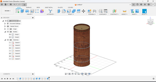
Creating the general outline was very simple. I first created a sketch of a circle with a radius of 6.5 in on the XY axis and extruded it 16 in. Then created a shell on the top face and made the inside thickness 5mm
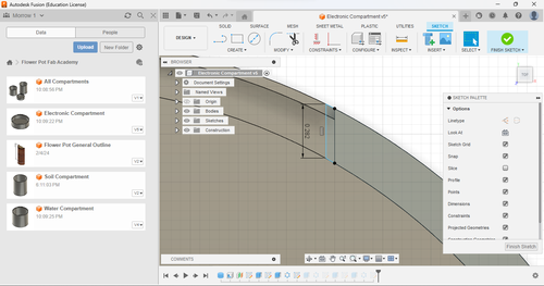
To add on, I wanted to created sketches that showed how long each part would be. I did this by creating a construction line up each distance that I had decided on in week 1 and created a circle at the end of each line. I then went up a little over 15 inches and created a circle on top of the the soil layer. I then extruded each of these 5 mm and made sure that the operation setting was join and in the soil layer’s case, a new body so that I can make the appearance differeant than the rest of the body.
Now I started to add an appearance to the design. I decided on cherry wood for the flower pot and as a stand in for my soil, I chose light brown fabric. Now I had finished my general outline.
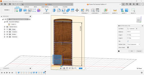
Cross Section
Making Electrical Compartment
The electrical compartment is by far the most complicated compartment of the three. For now, I wanted to focus on getting the ‘twist on’ and dimensions correct. The electronic component would include the spot that the tab fits into and the tab itself due to it being in the middle.
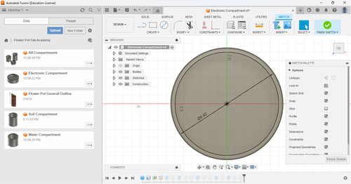
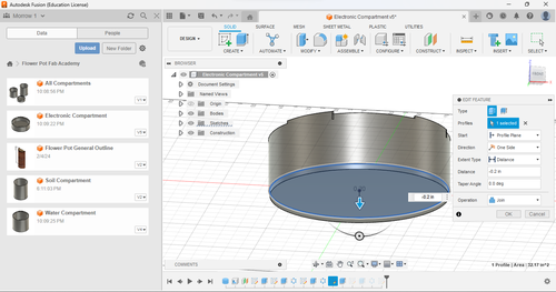
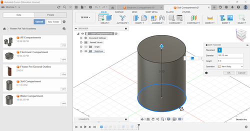
First I had to create the general shape of the compartment. I started by using the cylinder tool which made a cylinder when you specified a radius and height, for me I followed my design and made it a diameter of 6.5 inches and 2 inches for the height
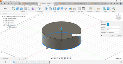
Next I shelled the cylinder using the shell tool by clicking the top of the cylinder for my opening and made the inside thickness .25 inches, this will give enough room for my twist design.

Now I wanted to create the ‘rail’ that the tab would sit on and could be twisted so that it will fit into what it was attaching to and stay in that position. To do this I created an offset plane 1.7 inches off the XY plane.
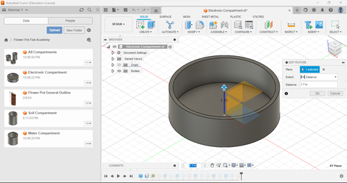
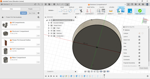
Now that the offset plane was created, I made a sketch off the plane and made a circle with a diameter of 6.4 inches so that when I do the cut extrude, it won’t cut all the way through.
I then extruded this .2 inches so that there would be a ‘roof’ to my rail and made sure that the operation was a cut. A cut operation makes it so that the extrude your doing cuts into the object it collides with during the extrude.

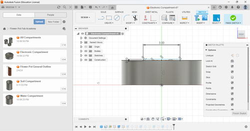
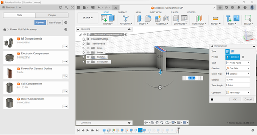
Then i wanted to make it so that the tab would go in on one side of the circle and once you twist it, it lockes in due to there being a ‘roof’ above it. So I created a sketch on the XZ plane and made a construction line that was 2 inches tall which is a line that is not registerd when exporting and is just used for designing purposes. I then made a rectangle that was centered at the end of the line which had a height of .2 inches and a length of 3 inches. The length was an abritrary number I picked out just for this draft and it determines the size of the opening for the rails and can be changed later.
I then extruded this to the edge of the cylinder and made sure the operation was cut.
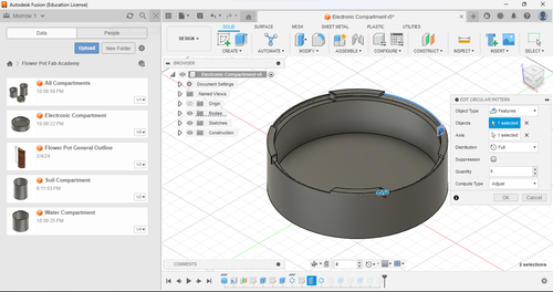
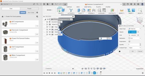
Once this was done, I created a circular pattern. I cirruclar pattern will copy a design you made around a circular ‘path.’ The amount and distance between each new ‘piece’ it creates along the path can be determined by the user. For my circular pattern, I selected the extrude in my timeline (which I will expand upon later) and chose a quantity of 4 and made the cirrcular pattern go along the entire path which I determined to be the edge of the cylinder. I also made sure the object type was ‘feature.’ This gave me the openings and roofs I wanted.
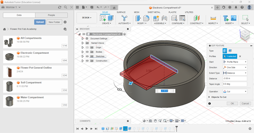
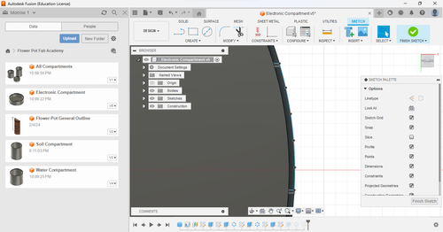
Now I wanted to make sure that you couldn’t twist the compartment too far so that it would pop out the other end of the roof. I made a sketch off the roof and used the fit-point spline tool to create a shape that fit the cylinder shape.
I then extruded this .3 inches so that it would reach the bottom of the rail. I made sure that it was it’s own body by selected the ‘New Body’ operation in the extrude menu, this would be important for the next step when I use the circular pattern tool again.
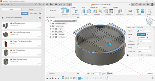
I wanted the stopper to be on every roof so I use the cirrcular pattern tool and made the object type feature, selected the extrude in my timeline, and made the path the edge of the cylinder.
Now I needed to make the tab that would fit into the rail. To start, I made a sketch off the bottom of the circle and made a cirlce with a diameter of 6.25 inches, making room for the roofs that come .25 inches in as stated earlier.
I then extruded this circle .3 inches down and made it a join operation.
I then created a sketch off the bottom of the circle and used the fit-point spline tool to make the edges of the tab that fit the circle shape.
I then extruded this sketch until it joined with the rest of the cylinder making it a join operation.

I then used the cirrcular pattern on the tab making it a quantity of 4, path being the edge of the circle, making the object type feature, and selecting the feature using the timeline.
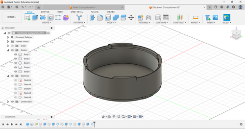
This is my completed electronics compartment
A problem that I realized while making the electronical component was that originally, the circle diameter on the bottom was too large. I realized this after I had created my entire electronic compartment. But, due to Fusion 360’s timeline feature, I can go back to when I specified the diameter of the circle and Fusion 360 updates all actions after that depending on what I changed in the timeline making the revision process incredibly easy.
Making Soil Compartment
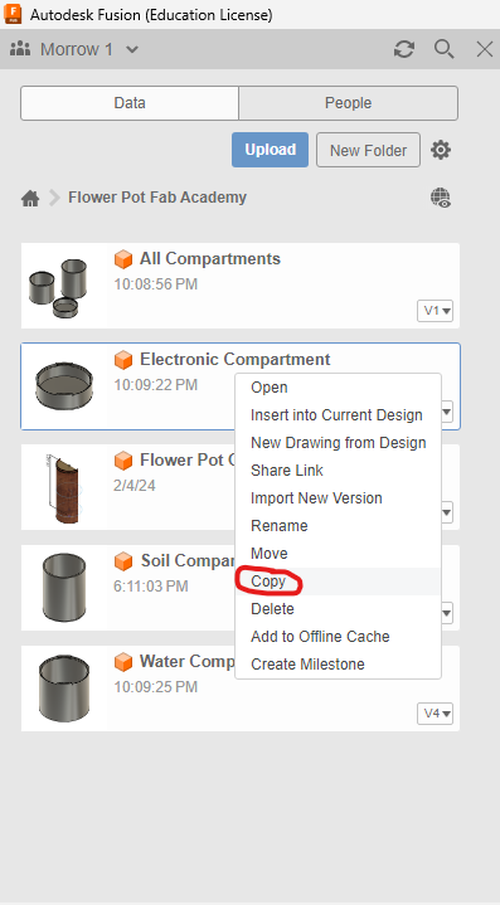
Making my soil compartment was very easy. Because my soil compartment is similar to my electrical compartment execpt for the exclusion of the top rails due it it being the top of the flower plant, I was able to copy the electrical compartment into another file and change a few things to make it different. I copied my electronical component by right clicking it on the data pannel and selecting copy.
All I had to do to create my soil compartment was deleted everything that related to the top rails in the timeline and increasing the height of my cylinder.
This is my compelted soil compartment.

Making Water Compartment
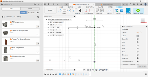
Making my water compartment was very easy as well. I copied my electrical component using the same method as my soil compartment and removed everything relating to the bottom tabs due to the water compartment being on the bottom of the flower pot and increased the cylinder height. I also had to increase the the length of the construction line that held my center point rectangle to the same length as the height of my cylinder (6 inches).

This is my finished water compartment.

Putting it All Together
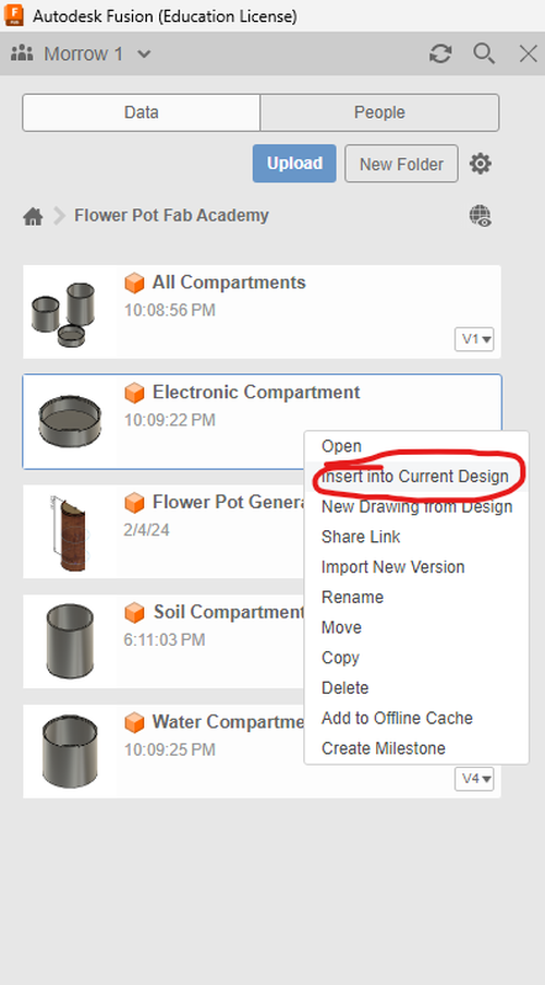
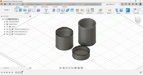
I created a new file on Fusion 360 and used the ‘Insert into Current Design’ feature by right clicking on a file in my data pannel and selecting the option to put all of these components into one file.
These are all of my compartments together
Review of Fusion 360
I find Fusion 360 very appealing to use. I like the fact that everything you make is saved to a cloud so you can access the files from any computer. I also like the interface and where everything is placed, it makes it very easy to access tools you need. The best feature of Fusion 360 is the timeline by far. Being able to go back and fix things you might have made a mistake on and it updating your entire design is a huge time-saver when you do make a large blunder such as my problem with the diameter of the bottom circle sketch. No complaints except for the fact that if I wasn’t a student I would have to pay for it.
OnShape
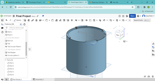
OnShape is an online CAD program that is extremly similar to Fusion 360. They both save files to cloud so you can access your files from any computer. The programs are so similar that the steps I used to create my things in Fusion 360 are the exact same for OnShape. So I decided just to create my water compartment, creating the water compartment was the exact same I would do if I made it from scratch on Fusion 360 instead of copying it. So I find there is no point to go through step-by-step if my workflow would be the exact same except for slightly different photos. That being said, here is my water compartment created in OnShape
Review of OnShape
Because I like how Fusion 360 works, I like how OnShape works aswell. The menus are simple and easy to navigate and I like how I can work from any device like Fusion 360. The only thing that I wished OnShape had was a parametric timeline like Fusion 360. Collin Kanofsky, a classmate of mine, showed me some of the other uses of OnShape that Fusion360 lacks such as assemblys which allow you to seperate differet parts of your design and design them seperately. Though, for my design, I didn’t see much use for the feature so it went unused when I was utilizing OnShape. Maybe if I change parts of my project or want to include things, the assembly feature would be helpful.
Unity
Unity is a game engine with it’s main purpose is making games. Inspired by Nicholas Niles user interface in his final project, I decided I wanted to understand the basics of designing 3D models in Unity so that I could incoorporate that knowledge in my final project’s user interface. I decided to just design a tree and not my water compartment like my other 3D CAD because I would primarily be using Unity as a user interface in my final project such as Nicholas Niles did in his final project
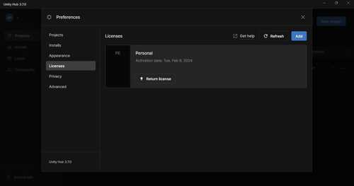
To start I downloaded Unity off of Unity’s website. I then created an account and set up a personal lisence by navigating to preferences, lisences, add and then person lisence inside Unity Hub. This automatically gave me a personal lisence.
I then started a new project from Unity Hub from the projects tab.
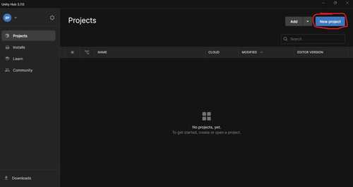
I then selected the 3D template, named it, and then clicked create project.

Once I loaded into my project, I realized how unprepared I was for Unity. The interface is pretty confusing for someone who hasn’t used a game engine before. Since I just wanted to create a 3D model for now. I found a tutorial by a channel called The RealTime Essentials on YouTube. This tutorial showed me how to install and use ProBuilder in Unity.
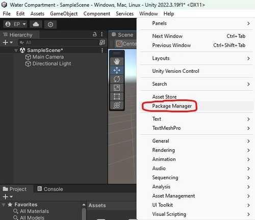
To start I enabled ProBuilder on my project. I did this by navigating to the Package Manager in the Windows tab on the top of the screen
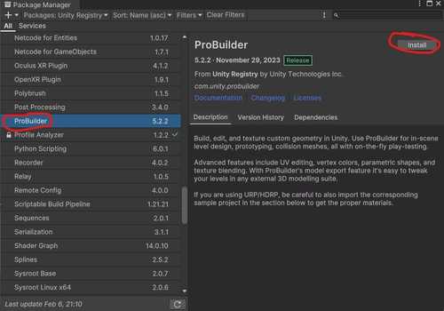
Then looking in the Unity Registry Packages I scrolled down until I found ProBuilder. I then clicked on it and then clicked install.
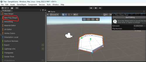
Once installed you will see a new tool tab on the top where you can select the ProBuilder tool.
The ProBuilder tool is a very easy tool to use. I was able to understand a good amount of it by messing around with some of the settings. With my experimentation and knowledge from the video, I realized while using the ProBuilder tool that creating just a tree with the ProBuilder tool would be very easy. So I decided to create a small ‘forest’ scene (using forest very lightly) using simple shapes.
To start I created a New Poly Shape tool and made a platform that would be the ‘floor’ of the forest by placing points that would create by base shape then once the shape became ‘closed’ I can define the height by moving my cursor up or down. I am able to change the position of each point on the base shape by draging the white squares on the shape. Because I will be using Unity for more of a modeling program, I will not be focusing much on the exact measurments of each shape.
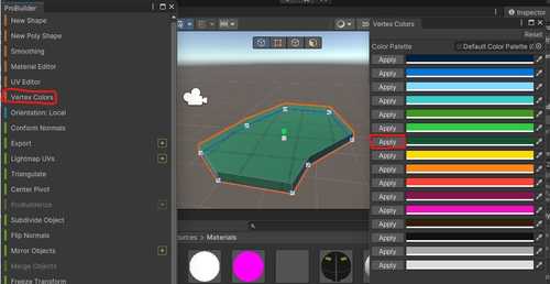
I then changed the color by using the Vertex Color tool, selecting the geometry I just made, and selecting apply on the color I want. I can provide a specific color by clicking on any of the colors in the Vertex Color tool menu and specifying it on a traditional RGB colorwheel.
I then made a cylinder and cone to create a tree by using the New Shape tool which has preset shapes you can make by dragging and clicking to create the geometry. I then used the Vector Color tool to color the cylinder brown for the trunk and the cone green for the leaves.
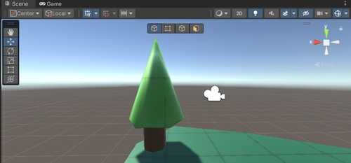
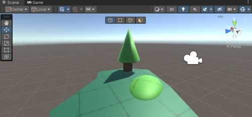
I then made a small bush out of a sphere and colored it a different shade of green than the ground.

Now my simple forest scene was complete.
Also, the file size created by Unity is incredibly large (Over 100 MB zipped). So, I will not be putting it into my download files.
Review of Unity
Unity is a much more complicated software than Fusion360 and OnShape. I found it confusing at first and what i have accomplished so far is just a proof that I can model a scene in Unity, even if it is not the best looking. One of Unity’s biggest strengths that I will be taking advantage on while I continue to use it to create a user interface for my final project is it’s tools that can be made by the community or Untiy itself. I used the ProBuilder tool which is created by Unity to create the scene. The advantages of these tools is that I can download a tool for my project that is made to do an incredibly specific thing that someone else made. A problem that I had with Unity is that sometimes it was a little slow such as when I started a new project or when I would be messing around in the studio. I believe these issues were caused due to lacking hardware on my laptop. I can fix these issues by utilizing Unity’s cloud to work on my much faster compueter at home whenever I need to utilize Unity.
Boxy SVG
I had used other vector and rastering softwares such as CorelDraw and Inkscape so i decided to learn a new 2D vector program. Boxy SVG is an incredibly simple vector program. I learned the basics from their website which had everything I needed to know on a short page with a few YouTube videos.
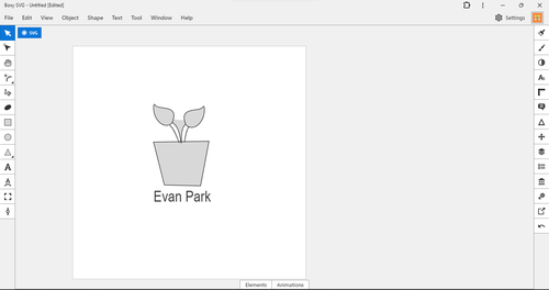
Once I had learned how to use Boxy SVG (which I learned is similar to CorelDraw and Inkscape), I wanted to create a small design that I would want to go on my flower pot. I decided to just go for a small flower pot with a plant in it that had my name.
To do this I used the two-point line tool to create the pot shape and the spline tool to create the stem and leaves of the plant. I then used the text tool to put my name below the pot.
This is my finished design in Boxy SVG
Review of Boxy SVG
Although this software is very easy to use which is good, it is too simple. Coming from CorelDraw and Inkscape which provide much more features than Boxy SVG, I felt limited when it came to what I wanted to do in my design. I couldn’t use a Quick Trace tool so I couldn’t edit another image and make it my own so I had to resort on my meager art skills to create something in Boxy SVG. Boxy SVG might be good for a beginner trying to learn vectors but too simplistic for someone trying to create something more than just a simple design.
GIMP
I followed this tutorial that I found on Adam Stone’s documentation which showed me how to change to file size, file dimensions, how to crop, and how to rotate. These were just some bare basics of GIMP.
I wanted to be able to raster this photo of a potted plant on a laser cutter. This image is created by Mist Somsa on vecteezy

To make it able to be rastered, I had to make it black and white. I followed this tutorial which I found on Adam Stone’s documentation. I then set all Hue Saturation levels on each color to the lowest setting and which gave me a file that I could raster on the Laser Cutter.

Gravity Sketch
We were lucky enough to be provied with Oculus Quest 2’s so that we would be able to use Gravity Sketech, a software that allows you to draw in a 3D space. This software also allows you to export your drawings to your computer. You can do lots of things with this software but in our case we decided to design something in gravity sketch and then 3D print it.

(Photo of Oculus Quest 2 Provided by CNN)
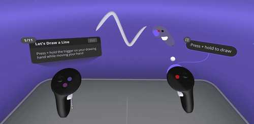
We turned on my Oculus Quest 2 and launched the installed Gravity Skecth app. I loaded into the app and started messing with some of the controls. Most of my time spent with the headset were spent messing with the menus and creating random things within the app. So when it came near the end of our time with the headsets, I realized I had nothing to 3D print so I just made a simple cube. Also, screenshoting within the headset was impossible due to the headsets being modified so that we were unable to take screenshots of what we were seeing. I was able to find a photo of what it looks inside of Gravity Sketch that was provided by the Gravity Sketch website.
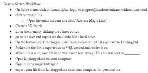
Exporting our files were a little confusing. But this was the workflow that we made as a group that allowed us to export our files to our computer so that we were able to download. Before you follow this workflow, you have to create an account on LandingPad. This is what the page looks like that your files will get sent to from Gravity Sketch

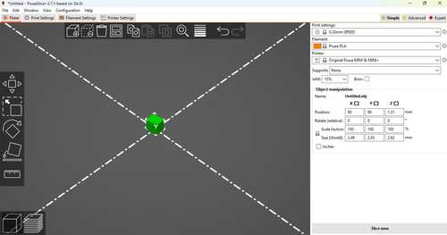
Now that I had my file on my computer I could 3D print it using my Prusa Mini 3D printer. I first went to PrusaSlicer on my computer and sliced my obj file so that it could be 3D printed.
I put my gcode file on a thumbdrive and plugged it into my 3D printer and clicked print. This is my finished product.

Review of Gravity Sketch
Gravity Sketch is a very new type of 3D CAD designing for me. It was very fun to experiment with the different tools. All menus are very simple and easy to use so it’s easy to be put into the app for the first time and start designing. The ability to design in a 3D space is a inutive concept that makes 3D desinging much more accessible to someone who hasn’t ever done it before. My only problems that I have with the software is that the file types that you can export can’t be edited by another software on your computer like Fusion360. Also, this type of software isn’t very accessible to most people so many won’t be able to try it. I believe if that the software was more accessible and you could your drawings in a different softawre, this could be the future of 3D CAD designing.
Downloads
You can download all the files for this week here
Reflection
This week was a tough one for me. I was unable to work on anything over the weekend due to complications and I fell behind very quickly. Although, I was able to catch up after a lot of work in a single day. Either way, I feel that I learned a lot from this week. I was able to compare Fusion 360, a software I have been using for over a year now with OnShape, a software I have only just learned to see which one will be better for my final project. I believe the timeline on Fusion 360 is too much to pass up for some of the extra features and OnShape and I am just more experienced overall with Fusion360 even though OnShape basically the same when it comes to designing. I was able to create an account for Unity and learn some modeling practices for it as well as how to install tools into a project. I am excited to start learning Untiy more for my user interface for my final project. As for Boxy SVG, I believe it is too simple to truly use in the future so I believe I will stick with Inkscape and CorelDraw for now.