12. Casting and Molding
This week we worked on Casting and Molding. I wanted this week to contribute to my final project so I decided to design a sprocket mold that will move my roller chain.
Research
The first thing I needed to do is find out how to design a sprocket for a designated roller chain. I found this helpful guide on how to design a sprocket for a roller chain by Clayton Ramsey on cheifdephi. I also needed to research my roller chain. I found out that my roller chain was an 08B-1. This meant I can search up the dimensions for that chain and use them when designing the sprocket. The dimentsions I needed were the pitch (p; distance from each roller), width (w), and roller diameter (Dr). I threw these dimensions into my parameters in my file for Fusion360 along with others that were used to create the sprocket that used the ones labeled previously for theiar values.

Fusion360
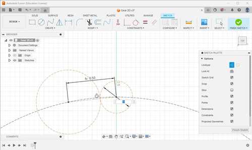
The first thing I did was make a sketch on the XY plane and make a circle with the diameter of my PD parameter and a chord with the length of p where one side ends on the intersection between the circle and the y axis.

I then made two circles on each end of the chord. One with the diameter of Dr and the second is tangent to the other circle.
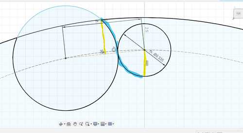
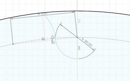
I then made a line perpendicular from the middle of the chord until it reached the edge of the circle, I then made a circle from the origin point to the end of that line. I then made a line straight down from my circle with the diameter of Dr. This line created by these two defined ‘edges’ will be the left while the rest of the circle is cut out.
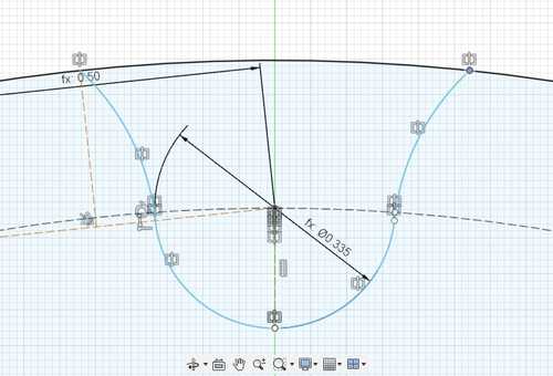
I then proceded to cut it out.
I then mirrored the line I created across the Y axis
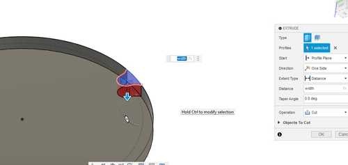
I then extruded the entire circle and then cut it out using the geometry I created
I then used a circular pattern and for my number I used my n parameter
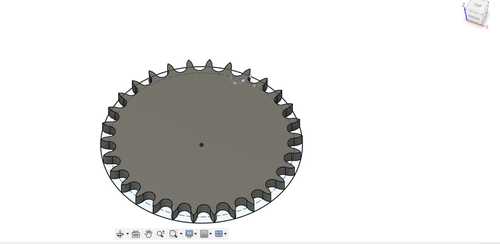
With a little bit of manipulating, I was able to create a two step mold that was for my 3D prints and a three step mold for milling.
This is my two step mold which can only cast soft stuff in it because it would be made out of hard material like PLA and cured resin.
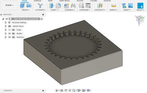
This is my three step mold design which can cast anything because you can create a soft mold which can cast your desired shape in any material because the mold is soft

Prusa Mini
I took my 3D print version of my gear mold model and put it into PrusaSlicer. I had to scale the print down slightly (about to 90%) so that it could fit on the bed. I did a .2mm Speed print with a 15% infill. I sliced it and sent it to my thumbdrive. Then I plugged my thumbdrive into my 3D print and started the print. This was the result of the print.

FormLabs
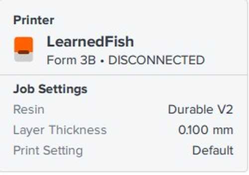
This was my first time using the FormLabs printer. The FormLabs printer is a printer that uses resin and cures it to create your 3D model. To start, I cleaned the build plate of the formlabs printer by taking it off and cleaning it with rubbing alcohol. I then went over to a computer and opened up the FormLabs software. I set my setting to our preset setting for our FormLab printer (Durable V2 Resin, .1mm Layer Thickness, and Default Print Setitngs).
I opened my 3D print stl mold and it was also too big for the printer. It asked me if I wanted to Auto-Resize it to the printer so I did so.
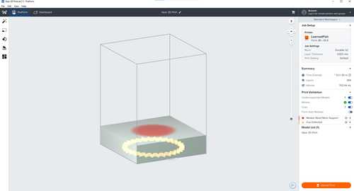
There were a couple of problems with the print. The first was that the Model needed more support and the second was that there were cups detected. To fix this, I used the auto orientate button on the top left which fixed all my issues and added supports.

I was now ready to upload my print to the PreForm, I clicked upload print on the bottom left and hit “Print Now” which sent the print. I then waited (20 hours) until the print was done. After the print was done, I sent it in an alcohol wash for 20 minutes and set it to cure for an hour, This was the result.
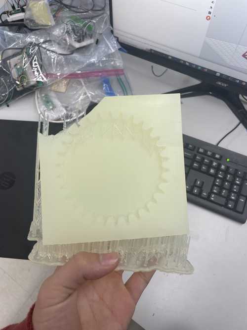
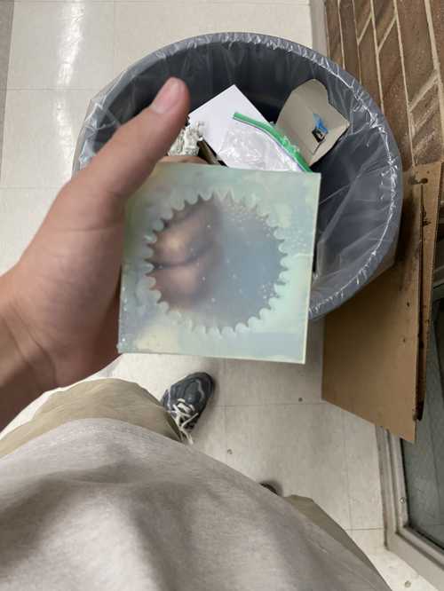
The print came out with the corner missing, this was due to the printer not having enough resin for the entire thing to print. To prevent this in the future, I should scale my model down as much as I can so that it is still serves it fuction without taking a lot of resin to print. Because of the hole, I would have to re-print a new mold, I edited the file a little bit to make it smaller and less thick but I still used the same process as above.
Milling
Aspire
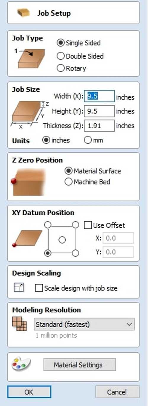
I took my 3D file of the milling versions that I created in Fusion360 and brought it into Aspire. I measured my piece of installation foam that I would be milling and got the dimensions 6.5x6.5x??? I put these into my job setup. These are the settings for my job setup.
Then I imported my 3D three step model using the import 3D model tool. The placing of the model in the 2D view was perculiar. Because I was using a thick piece of installation foam, I couldn’t use brads to keep it in place. So I had to hold it down by trapping it inside two wood pieces. I got two scrap pieces of wood and measured their widths using calipers. I got the measurements of about 2.5’‘, I put in a name X and Y on both of these accordingly so I knew what side to place these on when I started milling. In my 2D file, I measured a line that would extend the widths of the two planks for the X and Y plane, at the ends of these lines, I placed my model and then deleted these lines I created.
I then went into roughing the roughing toolpath tool which makes a toolpath meant to take out a lot of material quickly with little passes and set the tool to be two flute 1/4’’ diameter upcut spiral bit. I chose an upcut because it would be removing a large amount of material that I wouldn’t want to get stuck in the mill. I then calculated it

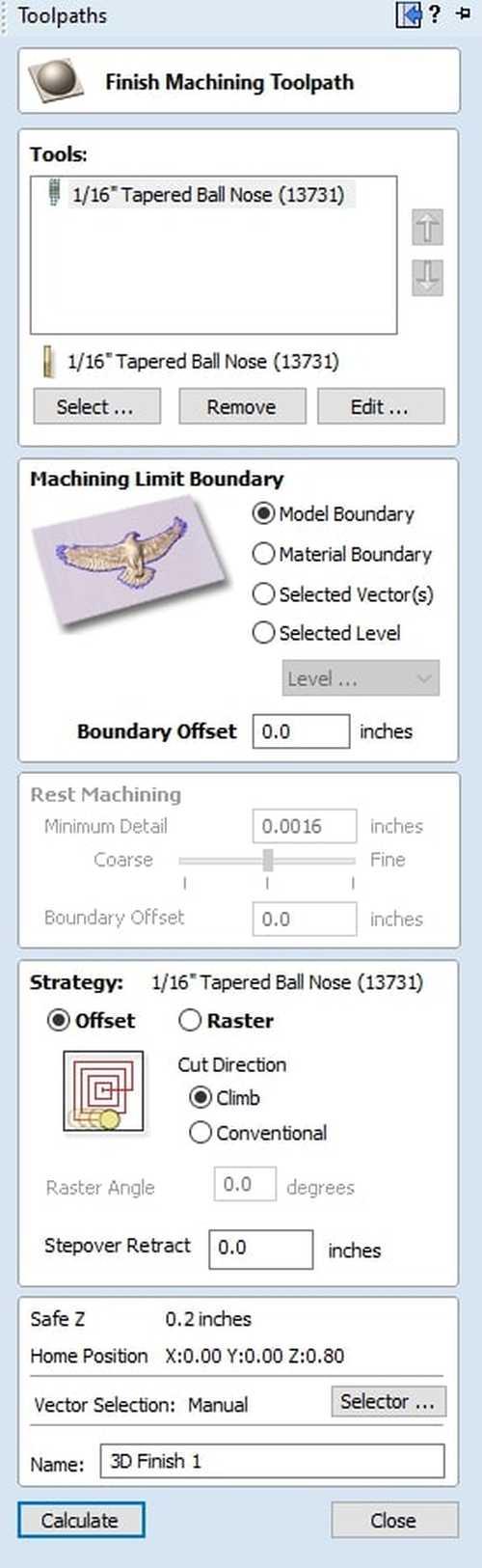
I then went into finishing toolpath tool which created a toolpath with more passes and set the tool to be a 1/16 inch tappered ballnose bit for a good finish on my foam. I then calculated this toolpath.
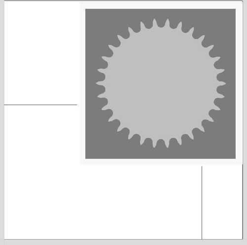
I then checked the 3D view and previewed the toolpaths and everything looked to be going accordingly.

I then exported the toolpaths for a ShopBot inch and uploaded the toolpaths to the ShopBot software. The computer was connected to a ShopBot Desktop.
ShopBot Desktop
For the material setup, I placed the two pieces of wood that would keep the foam in place which I offsetted on my file for and bradded them down. I then placed the piece of installation foam in the corner with nito tape where they meet and put more holders down that I could lock into place to keep the foam still on the other sides aswell.
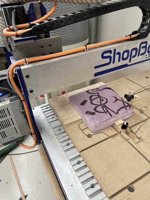
I zero’d the Z axis for the machine on top of the foam using the Z plate and also zero’d the X and Y axis using the proximity switches. I then inserted the roughing bit I was using with wrenches onto the ShopBot and ran my mill. This is what my material looked like after the roughing toolpath.
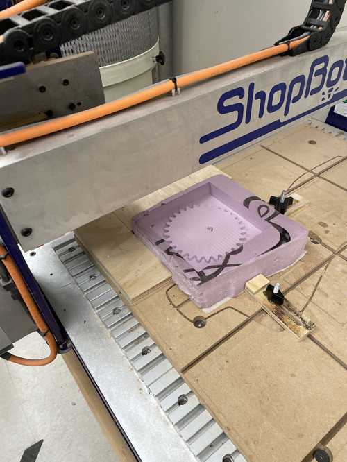
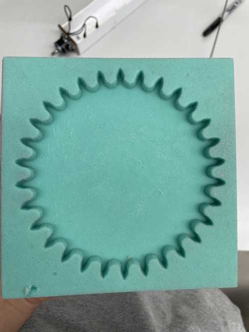
I then attached the finishing bit I was using and zero’d the Z axis again then ran the finishing mill, this one took a lot longer than the roughing mill because it had more passes. This is what my foam looked like compeltely milled after the finishing toolpath.

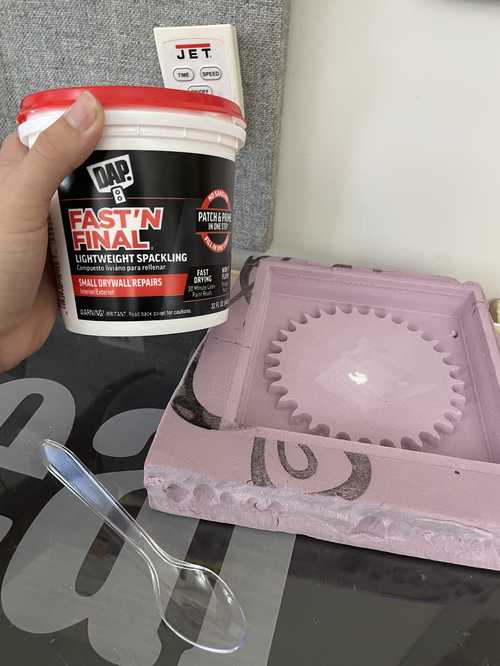
There was a problem with my installation foam, there was a large hole the middle that I though would be delt with when it was milled but it kept going. I threw spackle on the hole to cover it up but it will most likely hurt my finish.
Casting and Molding
Two-Step
For my two-step molds, I used Mold Star 15 slow to cast my gears. Before doing anything I read the datasheet for the material. The datasheet told me that I should wear saftey googles and gloves and that the mix between part A and B were 1:1 for weight and volume. I used weight to measure the ratios because I was using cups that didn’t have volume markers on them. This is my workflow for casting in the two-step molds using Mold Star 15.
- Spray Mold Release into your mold
- Stir Part A and Part B seperately and excessively making sure to get the sides and bottom of the container
- Pour the desired amount of Part A and Part B into cups, if you don’t get the correct weight ratio on the first try (which you probably won’t) pour out Part A or Part B as needed to get a 1:1 ratio
- Pour Part A and Part B into the same cup making sure you get everything into the cup
- Mix thouroughly and quickly
- Pour the material from a high altitude from the mold to reduce air bubles
- Once desired amount of material is poured in, poke out airbubbles using a toothpick
- Wait until the material has cured (4 hours of Mold Star 15 SLOW)
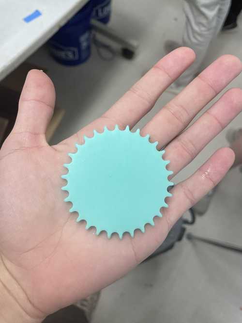
This was the result of my PLA cast

This was the result of my SLA cast
Three-Step
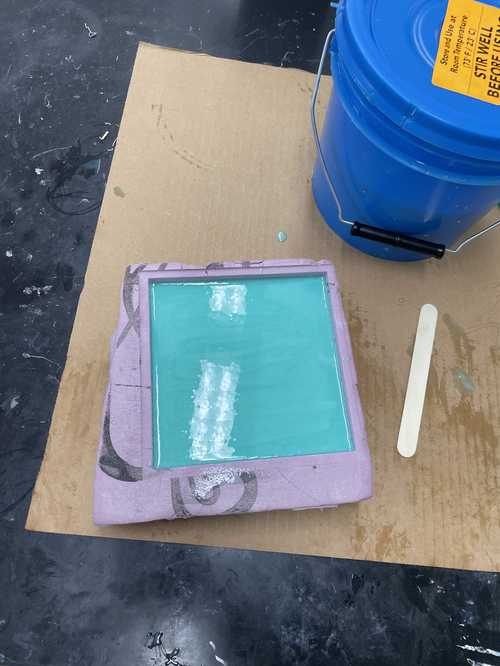
The three step process works the same as the two-step initally. This was because the first material I would use to create my mold was Mold Star 15 SLOW which meant that the second-step was the same process listed above. Except this time, I used volume to get my 1:1 ratio because I was using cups with incraments on them. To find the volume, I measure the dimensions of where I would be casting into and got the volume with simple math.
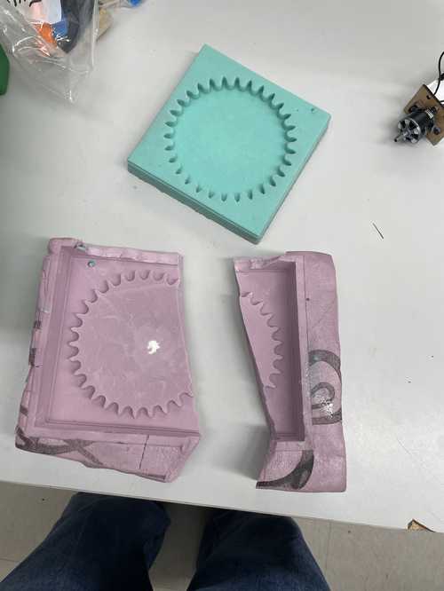
This was the result of my second-step of my three-step process
I had to tear apart my instalation foam to get my mold out.
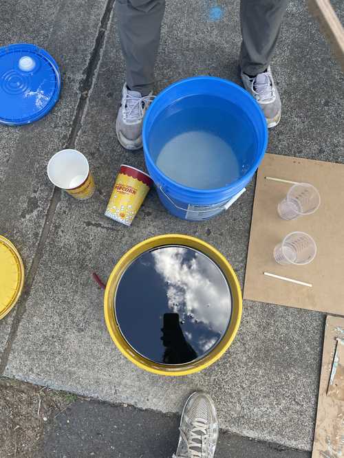
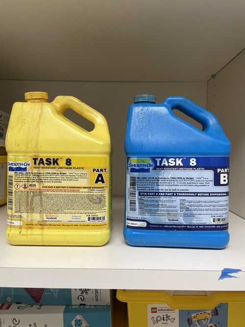
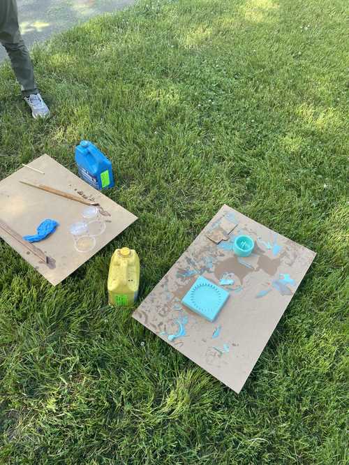
For my third-step, I was using Smooth-On Task 8 which is a heat-resistant plasic, perfect for my gear. I read the datasheet for it first before using. The volume ratio is 1:1 and I should use gloves and saftey googles, I measured my casting space as a cylinder. I decided to do my process outside so I didn’t get the material in the lab.
The intital buckets of Task 8 that I got were expired (by 4 years). This meant these were unusable
I found another task 8 part A and B that weren’t expired.
The process was the same as the Mold Star 15 Slow for casting for volume but here are some small details that make them differ.
- The Task 8 parts was in a portable container which had a lid so instead of mixing both parts before pouring, I shook them
- Task 8 cures incredibly fast so I had to work quick when I mixed the two together
- Task 8 becomes incredibly hot when curing so I made sure to move fast before the cups got too hot to handle with
This was the result of my three part mold.

Downloads
All my files for this week can be found here
Reflection
Looking back on this week, I enjoyed it. Although, due to a small change in my final project in how the tred will be made, the sprocket that I had designed for this week won’t help anymore in my final project. I still enjoyed the practices of designing a mold for 3D printing with SLA or PLA and milling with installation foam and just through this week, I can see how one can incooporate these skills into projects they are working on.