3. Computer Controlled Cutting
This week I worked on
Vinyl Cutting
I already have experience in vinyl cutting and using Silhouette Studio so I didn’t believe I had to research anything to understand how to do it.
To start a vinyl cut, I opened Inkscape, a vector software that I am familiar with. I then decided that I wanted to create an MFDoom sticker that included his mask and sweater. I decide to vinyl cut them seperate and line them up when transfer them onto my wanted surface. First I got a simple photo of his mask to vinyl cut that I got from Ivan Tavares on Pintrest. I put this into Inkscape and performed used the trace bitmap tool to turn the photo into a vector. I made sure when I made the bitmap I set it to ‘Edge Detection.’
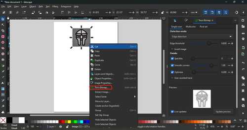
Once this was done, this was the vetor I got.

I made to save this as an svg
I then went onto Silohuette Studio and attempted to upoload my mask svg onto the program but I got an error that the file type was not supported. I fixed this by turning my svgs into pngs using this site. I was then able to upload by file onto Silhouette Studio.
I then edited the file so that the outline of the mask and the mask’s ‘features’ were on seperate files and started to cut the outline of the mask first.
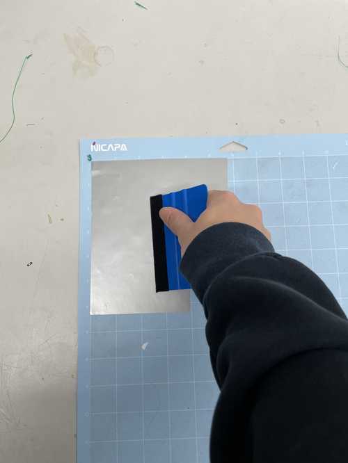
I did this by first chosing the color I wanted for the outline of the mask, I chose black. Then I stuck it onto the cutting mat and used a squeegee so that the vinyl was stuck to the cutting mat so that the vinyl wouldn’t move around when it was cutting.
I then went to my seperate file which held my mask features and cut that on a piece of grey vinyl using the same steps as the mask outline.
I then cut out each vinyl and then started to weed the unwanted parts of the vinyl using tweezers.
Before Weeding
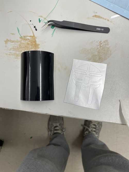
After Weeding

I then moved the mask features onto the mask outline using transfer tape and a squeegee.
![]()
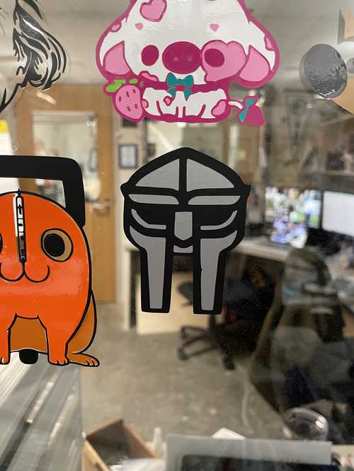
Then I put a new layer of transfer tape on top once the mask features had been moved so I could transfer the entire thing onto a window where we were all putting our vinyl stickers on.
![]()
My finished vinyl sticker on the window.
Group Project
Our site for our group project for this week can be found here. I worked on this project with Ryan Zhou, Landon Broadwell, and Conner Cruz.
Designing The Parametric Design Kit
I started by creating a few pieces that pieces that would be easy to use and allow me to create a large range of things. I decided I wanted to create basic geometry and see what I could create given the pieces. This is what I came up with
- Circle with slots every 90 degrees
- Long bar with three slots on each long end
- Square with one slot on each side
- A hexagon with one slot on each side
This is my first ever time creating parameters on Fusion 360 and creating a laser cuttable file on Fusion 360 as well so I kept what I was creating basic so I can put all my focus into understanding the parameters and how to design a 2D file on Fusion 360.
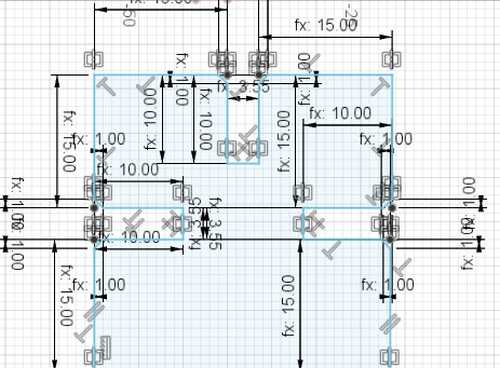
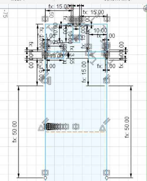
I created a new file on Fusion 360 and started to create some parameters, using the work done during our group project, I was able to created parameters that accounted for kerf and material thickness which allowed the slots to fit perfectly as long as the kerf and material thickness are set correctly. I did this by setting the perameter for slot length being ‘material thickness - kerf.’ I went a little overboard when it came to parameters, almost every measurement in my design had parameters in it. Although, I don’t see this as a bad thing because I am able to change the dimensions of a piece easily if they are not satisfactory. This is the screenshot of my parameters.

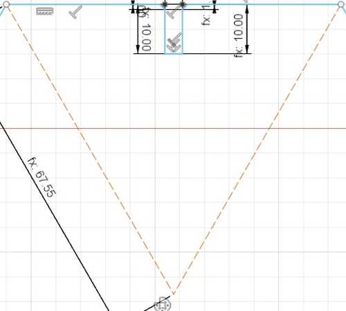
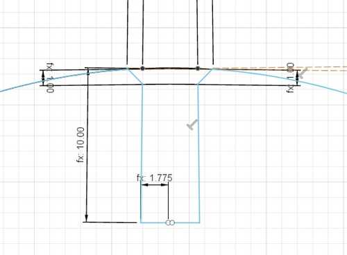
I then started to design the hexagon. I started by focusing on one side of the hexagon and created a line that was the same measurement as my ‘half-hexagon’ parameter. I then used the ‘slot_depth’ (which I set to 10 mm) and my ‘slot_length’ to create a slot that allowed the pieces to fit in with eachother. Once this was done, I wanted to find the center point of the hexagon I would create so I could use the circular pattern tool in Fusion360 to automatically create the rest of the hexagon. I did this by creating two construction lines off the sides which connected and set them both to 60 degrees so that the point at which they meet is my midpoint. Which gave me a design that looked like this. Also, I added a 1mm chamfer at the point where the slot and the edge of the hexagon meets. I realized that when I exported this as a .dxf file, the laser cutter would see the ‘dots’ that it makes in Fusion360 when you chamfer it.
After this was done, all I had to do was make a cirrcular pattern, set the objects to the design I just created except for the construction lines, set the center to the intersection of the construction lines, distribution to full, and quantity of 6 and it gave me the look I wanted.
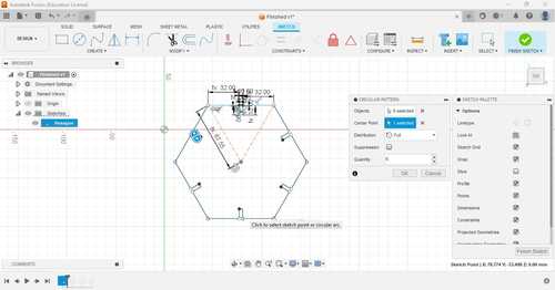
All I had to do was click ‘OK’ and then my hexagon was finished.
The square was basically the exact same as the hexagon. Instead of using the ‘half-hexagon’ parameter, I used my ‘half-square’ parameter. Also, when using the circular pattern tool, all I had to do was change the quantity to four and it gave me the design I wanted.
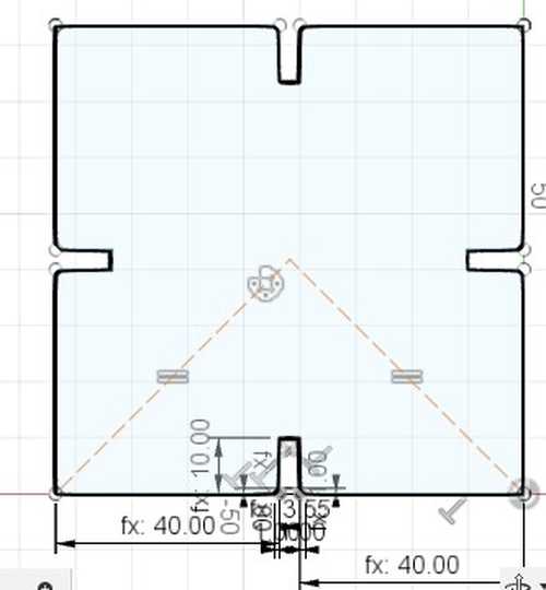
Then I started on my long bar. I started by making a square-type shape akin to the one I made above except I used my ‘half_plus’ parameter, I did each side by hand because I was unsure how a 3/4 circular pattern would work since the bottom side would not have a slot because that was the ‘long side.’ The edges were the same way I made the edges for the hexagon and square. I ended up with this.
I then added a 50mm line going off the bottom and added a construction line in the middle so that i could mirror the slots over on the other side of the long bar.
Once that was compelted I used the mirror tool on Fusion360 and selected the parts as the square part with slots and the mirror as the consturction line and it gave me the design I wanted.

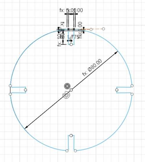
The circle was a little more trickey. To start, I created two construction lines going vertical and horizontal so that my circle was lined up. I then made the center point of the circle the intersection of the construction lines then set the diameter of the circle as my ‘cirlce_diameter’ parameter. I then created the slots in the circle by going down my ‘slot_depth’ parameter on the vertical consturction line then going left ‘slot_length/2.’ I then went up my ‘slot_depth’ parameter then used the I then created a construction line perpendicular to the slot depth then created a 1mm chamfer between the construction line and slot edge. I then mirrored what I just created across the vertical construction line I created in the beginning and used the trim tool to open up the slot. This is what I got after that process
I then used the circular pattern tool the same way as before and made it so that the quantity was four. This gave me the design I wanted
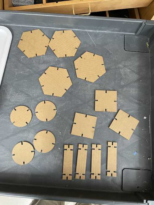
This is the photo of all my parts.

I then exported this file as a .dxf
Laser Cutting
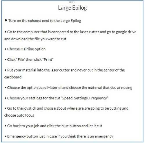
I sent my exported file over to the computer linked to the laser cutter. This is my workflow to laser cut on the Large Epilog.
This is my video of my file being cut out. I made sure to make multiple copies of the file so that I had multiple pieces.
These are the pieces after the laser cut.
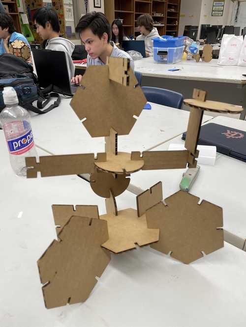
Each piece fit together exactly as I wanted them to so I didn’t need to change anything about my design. These are a few things I made using these pieces
Scarecrow

Warrior
Downloads
Download all my files from this week here
Reflection
I learned a lot of valuable skills that I didn’t expect to learn this week. I first learned how to create a 2D CAD file that could be laser cut in Fusion360 which I will be using in the future for laser cutting because I believe Fusion360 is the software I undetstand the most out of all the CAD softwares I know. I also learned how to design parametrically. The only regrets I have this week is that my design kit was very basic and unintresting. If I had more time then I would’ve loved to create a creative kit but time constraints prevented me from doing so.