14. Interfacing and Apllication Programming
This week I worked on defining my final project idea and started to getting used to the documentation process.
Research
I decied I wanted to use MQTT for this week. MQTT is an IoT communication that using a broker(server) to communicate between devices using a publish/subscribe system. Publishers send messages to the broker under a certain topic and subscribers that are subscribed to that topic recieve the message. I needed a chip that had wifi capabilities so I went with a Raspberry Pi Pico W for this week.
Mosquitto
To start, I downloaded eclipse mosquitto so I can use the fabcloud broker from my terminal. This was a simple download.
MicroPython
ThonnyIDE
I decided that I was going to use ThonnyIDE this week because I was programming a Raspberry Pi Pico W because it had a wifi chip which allowed it to communicate using IoT. ThonnyIDE was a simple download aswell. This would be my first time using python to code microcontrollers so it was a little bit of a learning curve to understand.
ThonnyIDE UF2
To program my Raspberry Pi Pico W, I needed to install the uf2 file into the chip. I went to this website to download it and held down the boot button while plugging the file into my pico using a USB which opened a folder in which I placed the uf2 file.
Node-Red
Node-Red is a low-code programming tool that is used for wiring together hardware devices. Node-Red has built in MQTT support so it made it easy to connect to a broker. To install, I ran this command in my terminal. I
npm install -g --unsafe-perm node-red
To start node-red, I ran this command.
node-red
This would start running on my local host which i would navigate to to start using Node-Red.
This downloaded node-red onto my computer. I decided to set this as a path so that I didn’t have to worry about what file I was in when I ran it.
Node-Red Dashboard
I also download the node-red dashboard add-on which will help later when I was making my GUI for this week. The download was a simple command.
npm i node-red-dashboard
PCB
I made a board for my Raspberry Pi Pico W in KiCad for a button, programmable LED, and analog pin for my poteniometer. I also added a few extra PinHeaders in case I needed them.
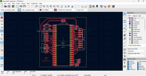
I then milled this board
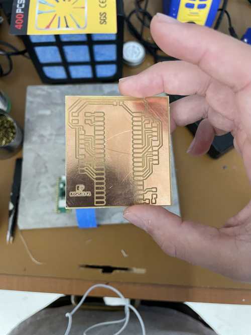
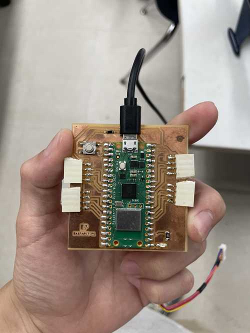
And then soldered it
Coding
Tutorials, Mistakes, and Testing
For this week, I wanted a Raspberry Pi Pico W communicating to my computer with MQTT to display a UI that displayed button state, controlled an LED, and read voltage on a poteniometer. The first steps was setting up MQTT on my Raspberry Pi Pico W
A large mistake I made when I was starting out was that I didn’t try to test MQTT from my terminal to make sure I was doing it correctly. This led to a lot of failed attempts which I had no clue why they weren’t working.
I started by following a tutorial by Tom’s Hardware. This tutorial used the umqtt.simple library to communicate with MQTT which was a simple install using the library manager. There were a lot of probelms when I tried following this tutorial. Everything on his code worked correctly for me except the MQTT connection and topic. Connor Cruz got his MQTT working pretty early on so I used his code and built upon it to work with through out this week.
The main changes I made to his code were the topics and the inclusion of a poteniometer reading. When I tried running the code, it kept failing. With some experimentation running MQTT through my terminals, I realized that my topic needed to start with ‘fabacademy’ but I could add anything else to the end of it as I wanted. This is me communicating between my two terminals using these commands.
mosquitto_sub -h mqtt.fabcloud.org -p 1883 -u fabacademy -P fabacademy -t fabacademy/fabstudent
mosquitto_pub -h mqtt.fabcloud.org -p 1883 -u fabacademy -P fabacademy -t fabacademy/fabstudent -m (message)
I then started writing my code for this week. Connor Cruz’s code covered the LED and button state, all I had to do was change the pins.
Poteniometer
I followed this tutorial for reading analog voltage, I had some problems with getting the correct voltage to display because the tutorial didn’t show how to map the voltage correctly. I thought I knew how to map this voltage because I have done this on ArduinoIDE. The inital mapping was done through this code.
voltage = value*(5 / 1023)
This still gave me the wrong voltage, after some research, I realized that the analog range from Arduino IDE that I was used to (1023) is different than the analog range that I was using in ThonnyIDE (65535). All I had to do was change the value on the code so the mapping ended up lookling like this.
voltage = value*(5 / 65535)
That ended up reading my voltage correctly. I also changed the button programming a little bit. I had it read if the button was pressed or unpressed instead of displaying when the button was pressed. The true line of code that I wrote for this week is this.
adc = ADC(26) #set analog pin

def pot()
# read value, map and then publish voltage
value = adc.read_u16()
voltage = value*(5 / 65535)
publish(voltage)

def buttonPress():
    buttonPressed = buttonPin.value()
    if buttonPressed:
        publish('fabacademy/fabstudent/button', 'Pressed!')
    else:
        publish('fabacademy/fabstudent/button', 'Unpressed')
This was my full code for my week
import network
import time
from machine import Pin
from umqtt.simple import MQTTClient
from machine import ADC

wlan = network.WLAN(network.STA_IF)
wlan.active(True)
wlan.connect('CLSLabs', 'clshawks')

time.sleep(5)
print('Connected:', wlan.isconnected())

mqtt_server = 'mqtt.fabcloud.org'
broker_port = 1883
client_id = 'fabstudent'
username = 'fabacademy'
password = 'fabacademy'
topic = 'fabacademy/fabstudent'

client = MQTTClient(client_id, mqtt_server, port=broker_port,
        user=username, password=password, keepalive=3600)

ledOn = False
ledPin = Pin(16, Pin.OUT)
buttonPin = Pin(0, Pin.IN)
adc = ADC(26)

def mqtt_connect():
    try:
        client.connect()
        print('Broker connected successfully')
    except Exception as e:
        print('Failed broker connection: ', e)

def reconnect():
    print('Reconnecting to broker')
    time.sleep(5)
    machine.reset()

def publish(topic, msg):
    try:
        client.publish(topic, msg)
        print(f'Published {msg} to {topic}')
    except Exception as e:
        print('Error publishing to topic:', e)

def subscribe(topic):
    try:
        client.subscribe(topic)
        print('Subscribed to topic:', topic)
    except Exception as e:
        print('Error subscribing to topic:', e)

def callback(topic, msg):
    global ledOn
    print(f'Received message on topic: {topic}; Message: {msg}')
    if msg == b'LED ON':
        ledOn = True

def ledBlink():
    global ledOn
    client.check_msg()
    if ledOn:
        print('ON')
        ledPin.value(1)
        time.sleep(1)
        ledPin.value(0)
        ledOn = False

def buttonPress():
    buttonPressed = buttonPin.value()
    if buttonPressed:
        publish('fabacademy/fabstudent/button', 'Pressed!')
    else:
        publish('fabacademy/fabstudent/button', 'Unpressed')

def pot():
    value = adc.read_u16()
    voltage = value*(5/65535)
    publish('fabacademy/fabstudent/pot', str(voltage))

try:
    mqtt_connect()
    client.set_callback(callback)
except OSError as e:
    reconnect()

subscribe('fabacademy/fabstudent/led')

while True:
    #Uncomment one call depending on input or output
    pot()
    ledBlink()
    buttonPress()
    time.sleep(1)
I then ran the subscribe and publish command from my terminal to check the wiring and code.
VIDEO OF PUBLISH AND SUBSCRIBE TERMINAL + PICO W PLEEEASE GET THIS
Everything worked! It was time to use Node-Red to publish, subscribe and create my GUI.
Node-Red GUI
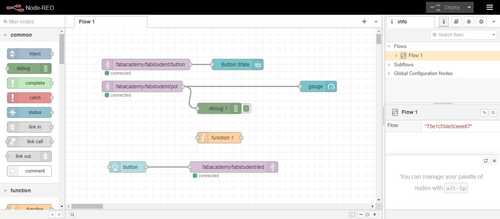
For Node-Red, I was following this tutorial by Kudzai Manditerza. This tutorial showed me the basics of using the MQTT in and MQTT out and utilizing the node-red dashboard. Although, a part of the tutorial caused me a lot of struggle. The problem was that they were using a fuction block before they sent their message to the gauge. I tried following this but the code didn’t end up working. I used the debug block to see if I was receiving the message correctly from the broker and it turned out I was. I deleted the fuction block and made it so that the message from the broker went straight to the gauge(which I set to be from between 0-5 for my voltage), and this worked. The gauge would change based upon the messages that were sent from what was being published to that topic. When deployed, the ui was shown at “localhost:1880/ui”
The GUI for the button was simple, just a MQTT in block connected to a text box from the node-red dashboard which I modified to my liking. The GUI for the LED was simple as well, just a simple button block from the node-red dashboard to make the LED blink. This is what my Node-Red workspace looked like for this week.
Here is the video of my GUI working!
Group Project
My group project can be found here
Downloads
My downloads for this week can be found here
Reflection
This week was a lot of trial and error. Problems that occur can sometimes be ambiguous and hard to figure out the problem. Earlier, before I had incooperated Connor Cruz code after attempting it myself several times, I had realized that the code I had for this week was all correct except for a small error (the definition of my topic/channel) that made me believe by code was completely broken. I was pleased with the UI I could put together in Node-Red and I appreciate Node-Red’s low-code approach to programming. Learning to communicate with MQTT has taught me important skills and also taught me to be resilliant when it comes to debugging.