10. Machine Week
This week I worked with a group to create a machine. These were the requirements for this week.
Group assignment:
- Design a machine that includes mechanism + actuation + automation + application
- Build the mechanical parts and operate it manually
- Document the group project
Individual assignment:
- Document your individual contribution
Group Assignment
Our process in making our CNC is shown in our group website, the individual contribution is broken down in there aswell.
My Work
This is the documentation of the work that I did/paticipated in.
Designing
Fusion 360
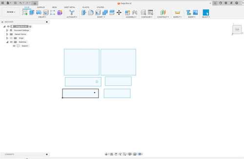
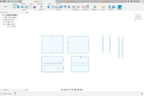
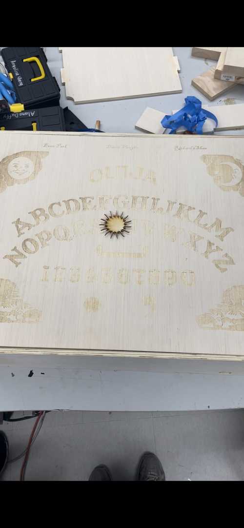
To start out creating the box, we designed a file in Fusion360 that will assemble the box that will hold our gantry and the rest of our electronic components. The top of the box will also have the Ouija Board engraved on top. We designed it in Fusion360 so that we could use parameters to change the size of the box if needed. We added a small panel for a button that we would use to activate the microphone that would pick up our speech and turn it into text for ChatGPT. We also added a hole for a USB for debugging and a hole to put your finger in and push the top off.
This is the file we created and a photo of the parameters

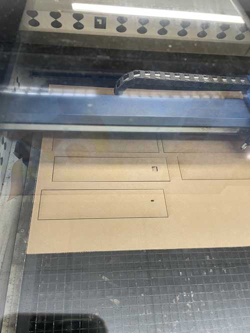
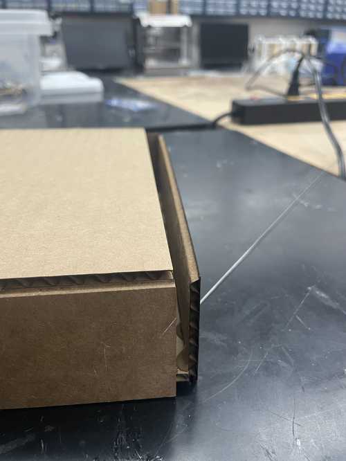
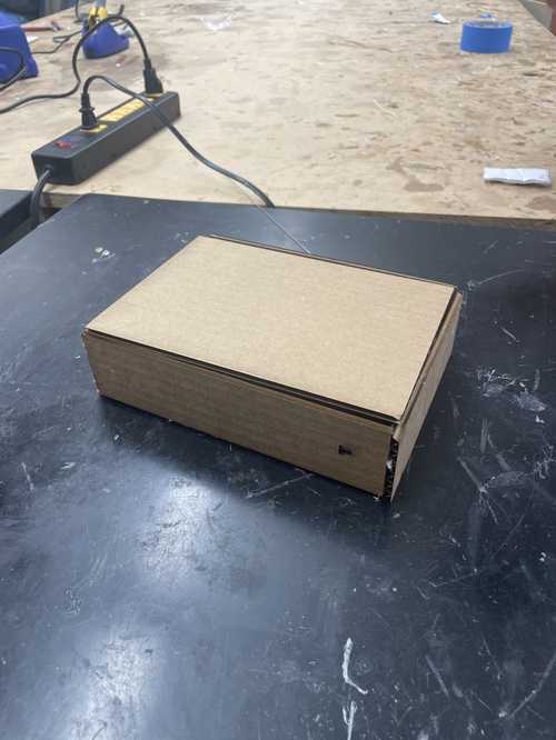
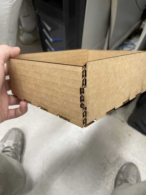
Laser Cut Tests
We decided that we wanted to laser cut our design on cardboard first to make sure everything fit as we wanted.
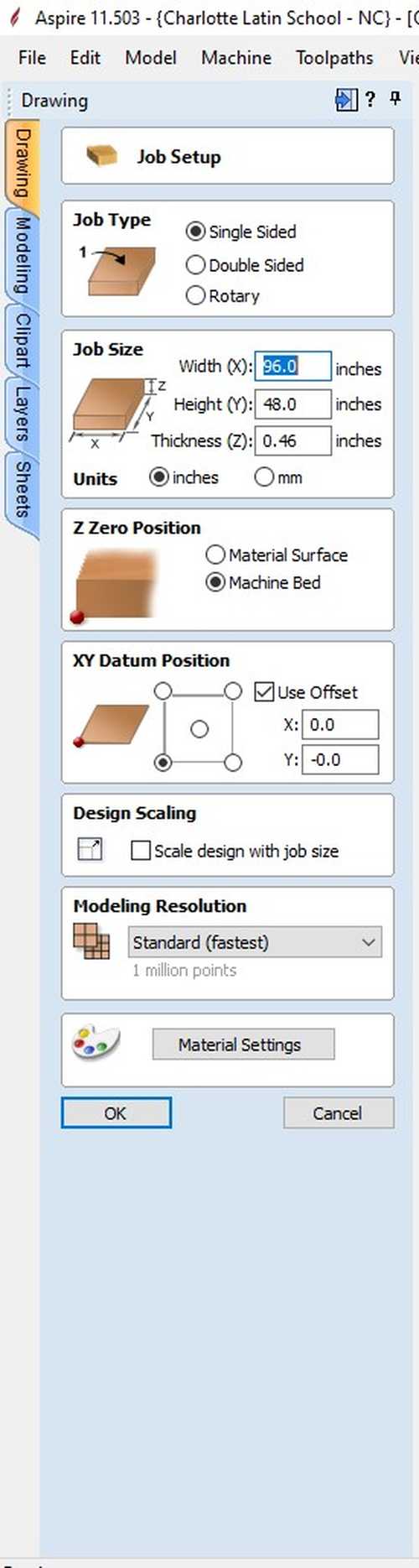
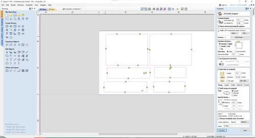
Aspire
We then took our DXF file into Aspire. We took a tape measurer and found that the length and width were 96’’ and 48’’ respectivly and with calipers we measured that the width was .46’‘. This was our Job Setup in Aspire
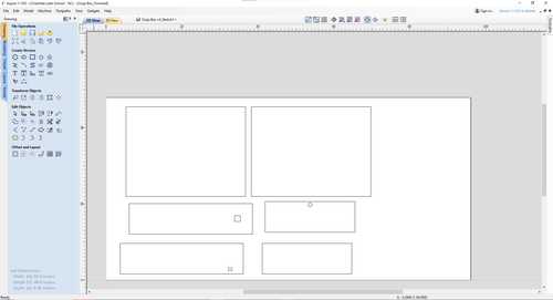
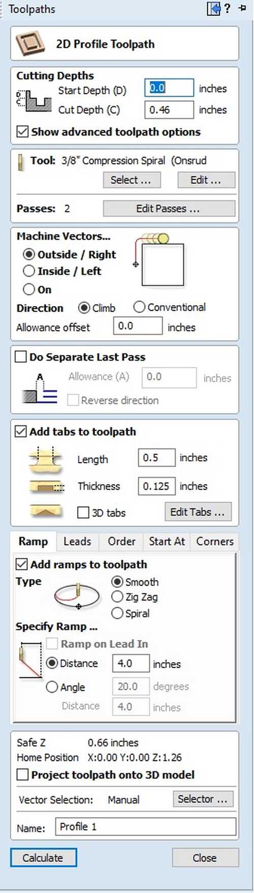
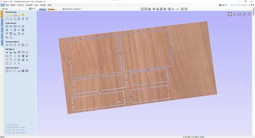
Then we added dogbones by using the filet tool and specified our tool radius and went along each finger joint and added dog bones so that they would fit when we milled them. We then used a profile toolpath. We started the profile toolpath by adding all the tabs we needed for our mill.
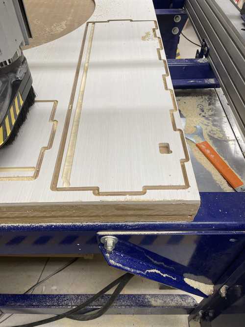
ShopBot
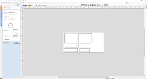
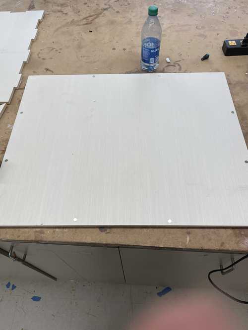
We were milling a wood that had already been milled before so we had to organize our file so it went around the already milled out parts on the wood.
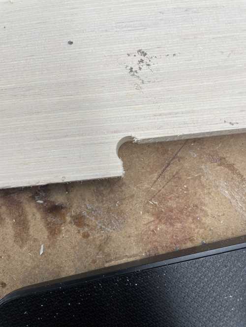
Post Mill
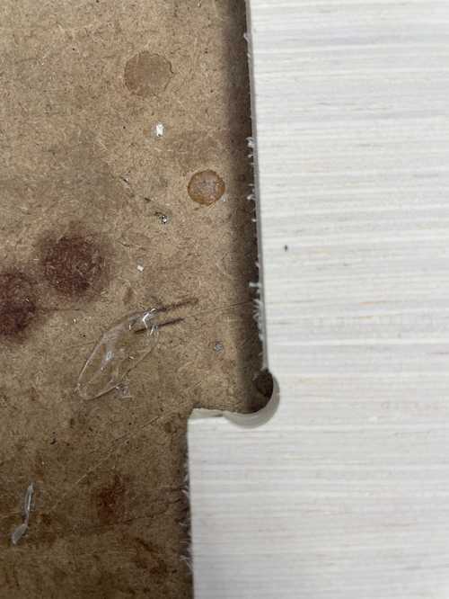
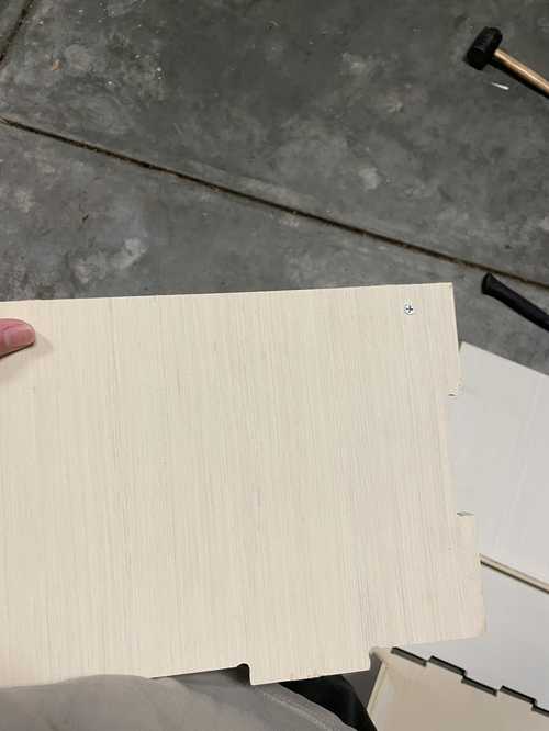
There were a few issues that we found out after we milled. The first issue was that we had milled the magnet holder on the box the wrong way.
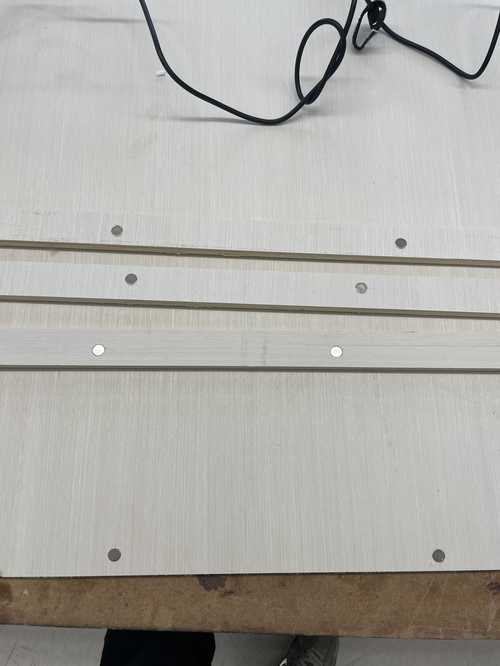
We were working around an already milled plywood so we had to rearrange our file so that it would fit on the wood. I used the same process as before to mill out the file but, while the file was milling, I realized that the tabs weren’t present. This was most likely due to my cut depth being too deep for the wood. This made the wood shift a little when the pocket toolpaths started. I stopped the ShopBot and put brads in each of the cut out pieces so that they wouldn’t move for the pocket toolpaths. Unfortunately, I stopped the cut a little late so one of the sides were a little bit scuffed but it didn’t cause any issues so we kept the piece.


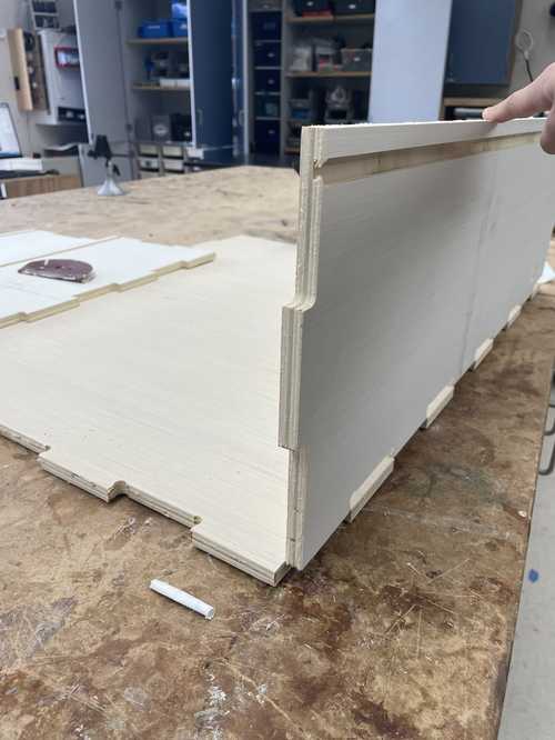
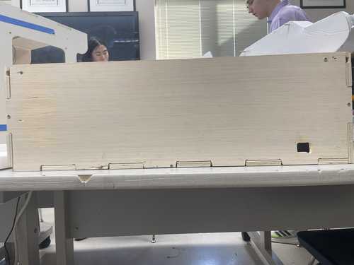
Assembly
Assembly of Box
Now it was time to assemble our pieces to create our box.
The first thing I did was screw the magnet holders onto the sides of the boxes. I did this by using a measuring tape to figure out the center of the magnet holder on the other side, marking it with a pen, and then screwing a screw into that mark. I did two screws for each magnet holder.
Gantry
For this project, we wanted a 2D axis gantry system which could be programmed using G-Code.
3D Printing Parts for the Installation
Many of the 3D printed parts we used in this build we got from Sand Table video. Below is a table of which designs we got and how many we used.
| Part | Image | Quantity |
|---|---|---|
| X-Carriage Mounts | 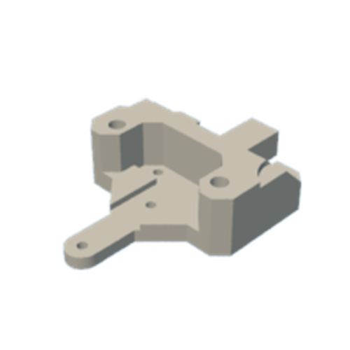 |
2 |
| Idle Mounts | 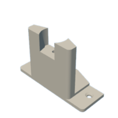 |
1 |
| Belt Grip |  |
1 |
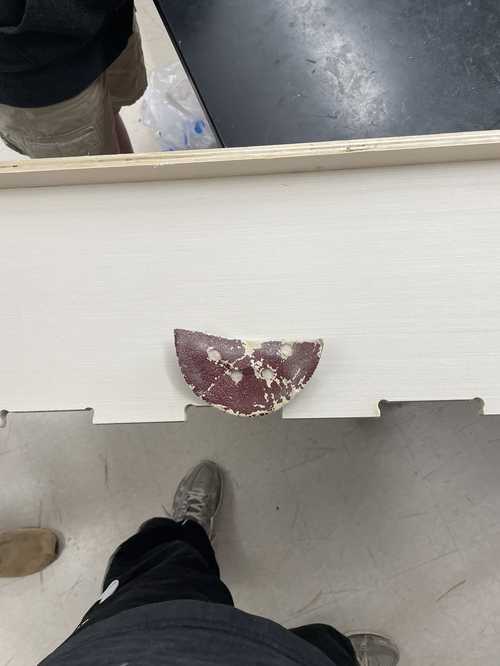
| Magnet Mount |  |
1 |
| Motor Bases |  |
2 |
| Wire Loops | 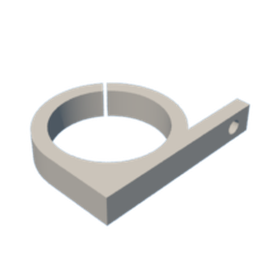 |
2 |
*Note that one of the motor bases must be mirrored horizantally in Prusa or other slicing software before print.
We eventually just printed a small cylindar to fit inside the magnet holder which we hot glued the magnet on the top of. One of the box’s holes was slightly off, but this could be easily fixed by using a soldering iron to melt away some filament, thereby extending the hole.
Assembling the Gantry
The gantry for this machine is based on one for a sand table by DIY Machines. Their video is really good for following the assembly of the gantry machine but we will still outline what we did.
We started by attaching the X carrages onto the X rails by using M38 screws for the carrage. We then attached the smooth idlers using M520 screws.
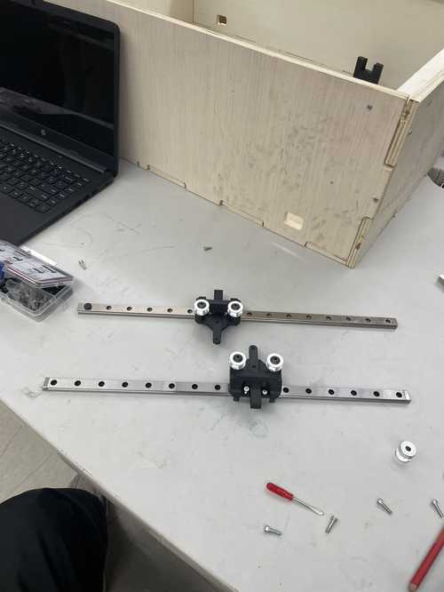
We then attacked the motors to our motor cases using M3*12 screws.

I then attached the X rails to the idler supports and motor mounts using M312 bolts. I was suggested to start using heat inserts for my screws and I used a certain tool to push the heat inserts vertically into my 3D printed motor mount. We would later attach a teethed idler onto it using M520 screws.

It ended up making the hole clogged with PLA and making a bolt impossible to go through. I had to take a hot air blower and heat the hole until I could push the heat insert out and then take an exactoknife and take material out of the hole until I could push the bolt through and put the nut at the end of it to hold it in. I decided to give up on the heat inserts after this.

We then put everything in the box at this point.
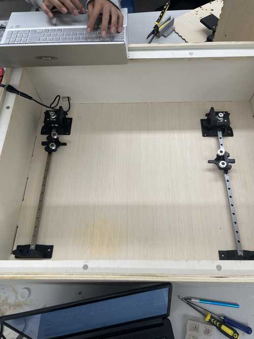
I then attached the Y axis by using M3*12 bolts.
We then attaches the magnet carriawge mount using M3*8 bolts onto the Y axis.

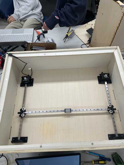
We then ran our belt around the mount going around each motor connecting everything using one belt
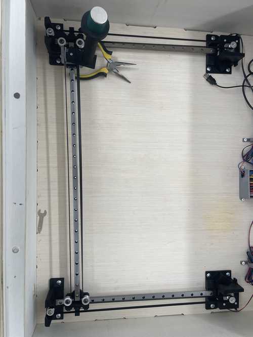
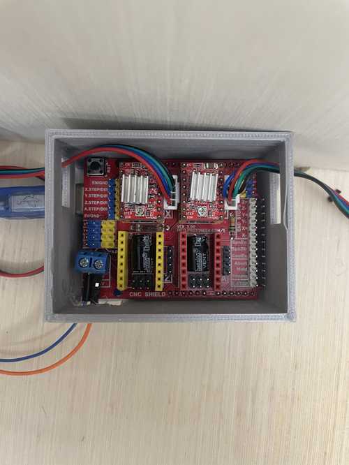
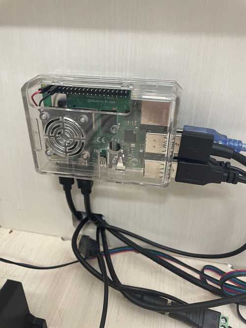
We then wood screwed our Arduino and motor mounts into the box. To make sure the motor mounts were squared, we used a triamgular ruler to measure each side and make sure everything was at a 90 degree angle. We then hot glued the Rasberry Pi to the side of the box near the outlet hole. We also attached the magnet holder to the magnet holder carriage mount using M3*8 screws.
We then installed some wire loops with wood screws for wiring organization.

Our box was ready to be programmed and run.
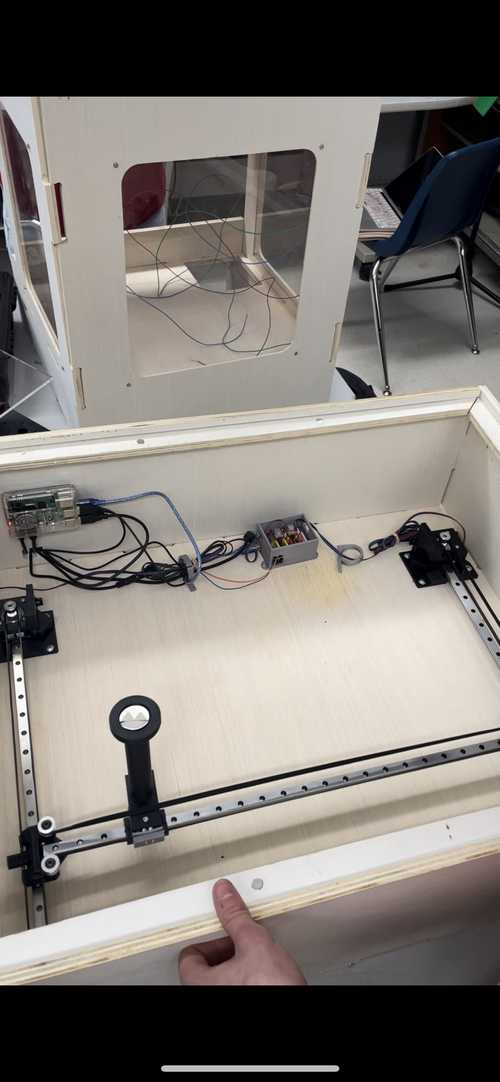
Installing the Gantry
To install the gantry system into the box (which we only did after we got all the programming working with the motors properly), we screwed some wood screws into the holes in the 3D printed parts at the ends of the x and y axes. We used a triangular ruler to make sure these were fairly straight and symmetrical. Additionally, we screwed down the wire holders and the box for the CNC Shield and Arduino.