7. Computer-Controlled Machining
This week I worked on defining my final project idea and started to getting used to the documentation process.
Research
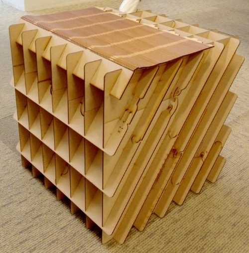
Mrs. Caycho from FabLab iFurniture showed us a technique called ‘waffling,’ a process where you take a 3D shape and slice it so that the shape is created by interlocking planes that are slotted into eachother. Here is a reference photo from Instuctables on Pintrest.
The first thing I wanted to do was a shelf that used this waffling technique, the shelves would be made by the spaces in between each plane. I decided tthat this idea was too easy and I didn’t have a real use for a shelf in my room because I had no real place to put it.
The second thing I decided on was a chair. I’ve seen a couple of chairs that have the waffle technique incoorporated so I was sure that it was possible.
Group Assignment
Our group assignment for this week can be found here
Designing
I knew I wanted the chair to have a dip so that it was flat, I also knew that I wanted the chair to have are rests on it too. This is the inital design I created in Fusion360.
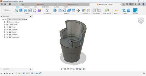
I exported the file as an stl and took it over to the softawre I was going to use for the waffling technique,Slicer for Fusion360. This software is now unsupported product by Autodesk but still available to download on their website.
Slicer for Fusion360
Material Setup
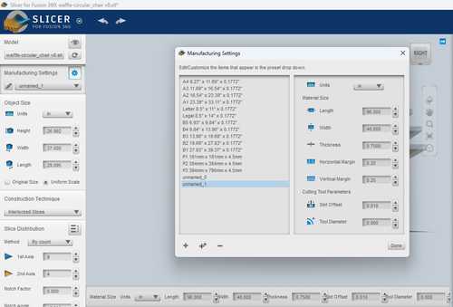
Now that I had the file in Slicer for Fusion360, the first thing I had to do before I sliced the file into interlocked slices weas figure out the dimensions of the material I would use. I took a tape measure and found the dimensions of the plywood to be 96’’ length, 48’’ width, and .‘75’ thickness. I created a new material setting in the Manufacturing Settings tab on the left.
Making the Slices
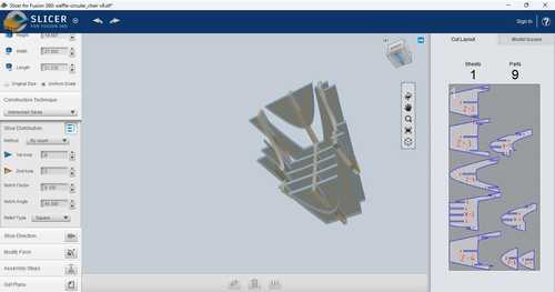
I then scaled the object and selected ‘Interlocked Slices’ for my ‘Construction Technique.’ For my method of Slice Distribution I chose ‘By count.’ I modified this count so that it only took 3 things of plywood to make all the slices for my chair. This ended up being 9 slices on the ‘1st Axis’ and 4 slices on the ‘2nd Axis.’ When I had done this, there was a small problem in my design. One of the notches on my slices was cut off at the end.

A started to mess with the settings to fix this issue and I found that once I changed the ‘Notch Factor,’ which modifies the start of the notch so that it has a chamfer depending on the value of the Notch Factor, from .1 to .8. I am unsure why this fixed my issue but it most likely because it modifies the way the piece is cut out as well.

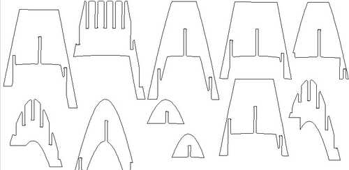
I also scaled down the file to a chair height of 27 inches so that the material would fit on one thing of plywood. These are the finished plans
Once everything was inspected and seemed to be working. I got the plans for the model by clicking ‘Get Plans’ on the left side and exported it to my computer as an EPS file, a file that Aspire, the CAD softawre I was using for milling, supported.
Aspire
Job Setup
Here are the settings I used for my Job Setup
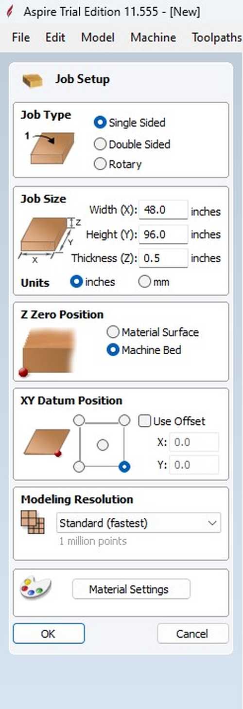
I imported my ESP files into Aspire by utilizing the ‘Import Vectors’ tool from the File Operations in the Drawings tab.
Dog Bones
Now that I had imported my ESP files into Aspire, I had to modify it a little bit. Mrs. Caycho informed us that we needed to add something called ‘Dog Bones’ if we wished to use the waffling technique because since a drill bit is normally circular, the notches created will not have right angles and will not fit well due to that. I decided to add Dog Bones in Aspire because there is a provided tool in there that automatically creates Dog Bones for you. If you select the Fillets tool in the drawing tab, there is an option for Dog Bones. I put in the tool radius as it asked (that being .1875’‘).

I then went through each notch and put Dog Bones in each one.
Before Dog Bones

After Dog Bones

I also deleted all of the numbers that were transfered over to the file because I didn’t want it to be detected as a toolpath.
Here is my file after I finished in the 2D View
Toolpaths
The first thing I did was download our Lab’s Tool database for Aspire. I did this by going into the Toolpaths --> Tool Database --> Import tool database and then select your tool database.
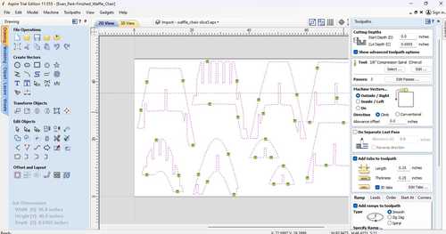
I then selected my vectors in the 2D view and then selected “Profile Toolpaths” in the toolpaths side bar. I defined the cut depth as the thickness of my board (.6955’‘) and I also added tabs and ramping to my cut. Tabs make it so that your cut will stay connected to your material so that your cut doesn’t mess up do to it being moved. Aspire can place tabs for you automatically but I decided to place them manually because Aspire was putting tabs in my joints. The ramping makes it so that the ‘plunge’ into the board is done while the bit is moving and dispersed along a path, I made the distance of my ramp 4 inches. Along with this I defined my bit as the 3/8’’ compression bit that I got from out Fab tool database because compression bits are good at avoiding chipping the wood which is important to avoid for joint like mine.
This is a photo of my settings and the 2D view of my tabs.
I then clicked Calculate and it created the toolpath.
In Aspire, once you calculate a toolpath, you can check what the toolpath will do in a 3D simulation under the 3D View tab. You do this by going to “Preview Toolpaths” which will allow you to run a simulation of the toolpaths that you have made. After checking my toolpaths, I saved my toolpaths by selecting “Save Toolpaths” and selecting the ShopBot inches setting. I realized though, while saving my toolpath, that I used the trial version of Aspire. This meant that I was not allowed to save my toolpaths. This meant I had to redesign the dog bones and tabs and toolpath on another computer that had the paid version of Aspire. I used the exact same process to do it as I did on the trial version.
ShopBot Workflow
Most of the workflow was created by Zach Budwichkowski but some parts are modfied by me as I saw fit if my process was different.
Start of Day
- Turn on the computer
- Log in to the computer
- Turn on the Shopbot
- Hit the blue Reset button on the controller
- Turn on the air compressor by turning the red switch clockwise
- Engage spindle by turning the interlock key clockwise
- Go to Cuts Menu then select CN 10 - Start of Day
- A window will eventually ask you to turn on the spindle, click the green button on the controller and click OK
- Put the magnetic dust boot on the spindle and press OK
Numatic Gun
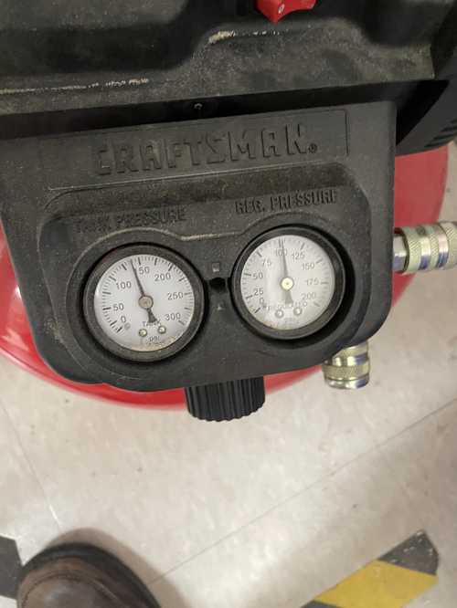
- Connect numatic gun to air compresor
- Turn on the air compressor using the red switch
- Utilize the black knob in the front until the tank pressure is about 150 and the regular pressure is about 100
- Take numatic gun and load polymer composite nails into it
- If your wood is bowing, use clamps to clamp it down so that the wood is flat
- Use the Numatic Gun to insert the polymer composite nails into it. -If your polymer composite nails aren’t holding the wood in (like mine), insert the polymer composite nails at an angle so that it sticks in better
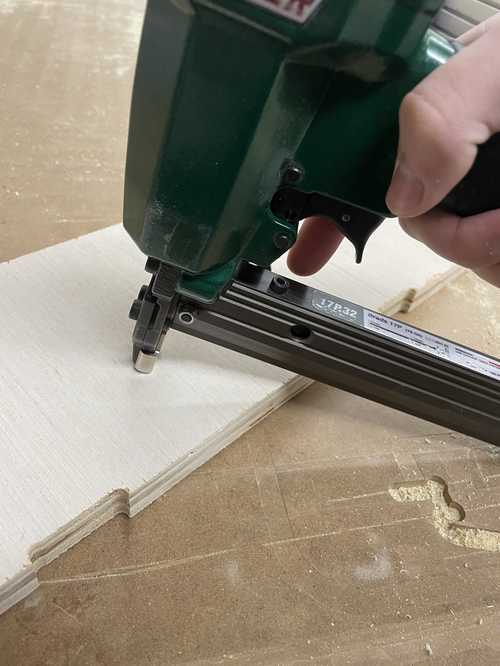
- Put as many as you need on your wood so that it is stuck onto the bed

Air Cut
- Go to Part File Load and upload your toolpath
- One of the changes that we need to be aware of with this new tool is that the 3D Offset procedure is now different than in the past. With ATC the prior 3D Offset routine triggers the Z-limit switch after a tool change. After consultation with ShopBot we learned that we can no longer use the 3D Offset routine and need to go with a temporary Z-zero routine instead which is outlined below.
- Once you have secured your material to the spoilboard, bring the spindle to the origin (JH) and set the Z-Height to 1 inch above your material. (Ex. JZ1.5 for 0.5”plywood).
- Use the Zero-Z-Axis (Zz) command to zero the Z-axis for a new temporary origin above the material
- Run your file with no offset and it will run as an aircut.
- Once the routine is complete, run the C3 command to rehome the machine and reset the Z-zero height to the machine bed
- Turn on the dust collector.
- Load the file once again and run the file with no offset.
Removing Tabs
- Take the brushelss motor and hold it against your tab
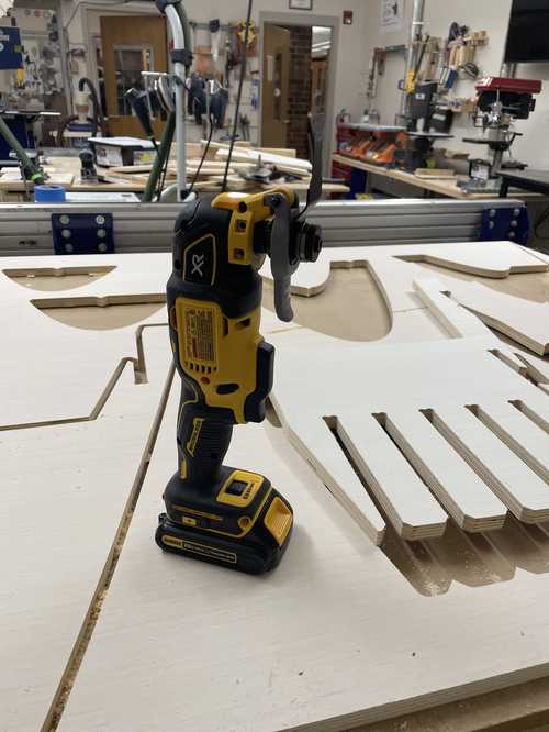
- Press the button on the side and push it through the tab until it is removed
- Repeat until the board is stuck onto the bed
End of Day
- In ShopBot software, Go to the Cuts Menu
- Select C11 - End of Day
- Take off the dust skirt
- Place the dust skirt near the computer keyboard
- Click ‘OK’ on the window confirming you have removed the dust skirt.
- Turn off the air compressor by turning the red switch counter clockwise.
- After the air compressor has drained through the spindle, turn off the Shopbot.
- Disengage the spindle by turning the key counterclockwise.
- Turn off the dust collector.
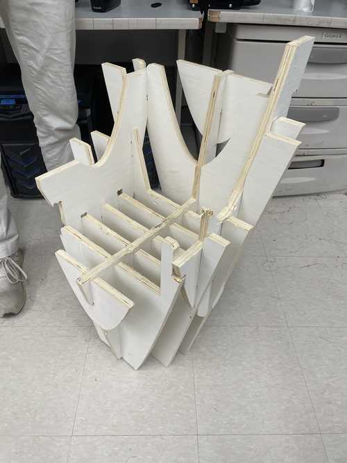
This is the board after the mill was finished with some parts of my mill taken out

Assembly
The joints of my chair were incredibly tight, most likely due too meager work with calipers. I used a hammer to force the joints in and wood to make sure I didn’t hard the wood when hitting it with the hammer. My classmate David Vaughn helped me hold and hit each joint into eachother. This is the chair completely assembled and this David Vaughn sitting on the chair.

Downloads
My files for this week can be found here
Reflection
Although I had already used the ShopBot to mill something, this week was a good refresher on how to use it and this time it was more challenging because it was a much larger project. This week also taught me waffling utilizing the Slicer for Fusion360 software.