13. Embedded Networking and Communications
Assigment for this Week
Group assignment: - Send a message between two projects - Document your work to the group work page and reflect on your individual page what you learned
Individual assignment: - design, build and connect wired or wireless node(s) with network or bus addresses and a local interface
UART
At first, I experimented with using UART which communicates informations through Rx and Tx pins. On a breadboard, I set up two RP2040s. I made sure that the GND and PWR was connected on both boards. I also connected the Tx and Rx pins on both boards. The wiring looked something like this
GND<—>GND PWR<—>PWR TX<---->RX RX<---->TX
I used the SoftwareSerial library for Arduino which is a library for UART communication. With many experiments and research, I was unable to get these two RP2040’s to communicate using UART. I decided that I should try some other communication method.
I2C
I decided that I wanted to use I2C to communicate between two XIAO RP2040s. I2C utilizes the SDA and SCL pins to send information between devices. It detects the device using adresses that are assigned. The wiring looked like this.
GND<—>GND PWR<—>PWR SCL<---->SCL SDA<---->SDA
I2C has a master and slaves. The code for the master differentiates from the slaves. Typically, the master doesn’t have an address while the slaves do. I wanted the master to be hooked up to a potentiometer connected to an analog pin start moving a servo motor on a slave when the resistance is low enough so that the voltage is max (5V). I used the Wire.h library in Arduino IDE to communicate with I2C. I decided to communicate using a breadboard this week.
Problems I Encountered
For a while, I was having some problems getting the correct number I was sending to the slave from the master. I was trying to Wire.read();" from the slave the Wire.write(val); command where val = 1 But instead, I kept getting a value of -1. My classmate David Vauhgn reccomended to me that I change my Serial.begin(9600); to Serial.begin(115200); which fixed the issue.
Arduino IDE
Master
Upon researching the library, I understood it’s functions. For the master and slave, I needed to Wire.begin to start the communication. For the master, I would need to begin a transmission using the Wire.beginTransmission(address); then Wire.write(); that the pot was at max voltage and then Wire.endTransmission(); after. I had this function run on an if statement for when the voltage was max. This code is a modification of the code I used for input week.
#include <Wire.h>

int val = 1;

void setup() {
  Wire.begin();
  Serial.begin(115200);
}

void loop() {
  int sensorValue = analogRead(A0);
  float voltage = sensorValue * (5.0 / 1023.0);
  Serial.println(voltage);
  if (voltage == 5){
    Wire.beginTransmission(8);
    Wire.write(val);
    Serial.println("sent");
    Serial.println(val);
    Wire.endTransmission();
    delay(1000);
  }
}
Slave
For the slave, you set the address in the Wire.begin(address) which I had initally set to 1, when I ran my code, it didn’t work. Upon further research, I found out that the address should be a integer higher than 7 due to the amount of bytes it takes to process the address. So I set my address to 8 which allowed the two RP2040s to communicate. My code is a modification of my code for output week which is derived from Richard Shan’s code for output week.
#include <Servo.h>
#include <Wire.h>

Servo servo;

void setup() {
  servo.attach(D0);  // attaches the servo on pin 1 to the servo object
  Serial.begin(115200);
  Wire.begin(8);
}

void loop() {
  int val = Wire.read();
  if (val == 1){
    for (int pos = 0; pos <= 180; pos += 1) {
    // goes from 0 degrees to 180 degrees in steps of 1 degree
    servo.write(pos);              // tell servo to go to position in variable 'pos'
    delay(15);                       // waits 15ms for the servo to reach the position
   }
   for (int pos = 180; pos >= 0; pos -= 1) {
    // goes from 180 degrees to 0 degrees
    servo.write(pos);              // tell servo to go to position in variable 'pos'
    delay(15);                       // waits 15ms for the servo to reach the position
   }
  }
}
Breadboard Video
This is the video of the two micorcontrollers communicating on a breadboard. When the analog pin reads max voltage from the pot due to lower resistance, the servo moves.
PCB
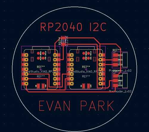
KiCad
Now that I had it working on a breadboard, I created a simple board in KiCad. I already knew the wiring because of the breadboard so the pcb desing was a simple process.
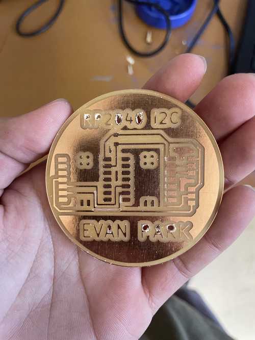
Milling
I exported the file from a KiCad as a gbr file and went to my OtherMill to mill out the pcb. This was the result.
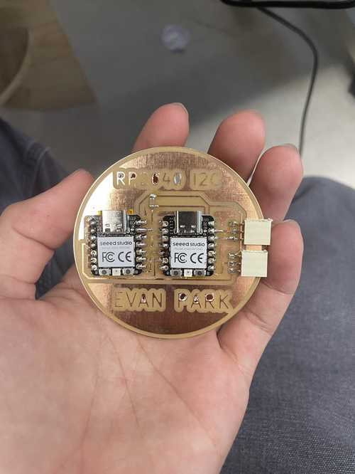
Soldering
I then soldered it together with a 970 uf capacitor, 2 1x7 vertical 2.54mm Pinheaders, and 2 1x3 horizontal 2.54mm Pinheaders.
PCB Video
This is it running on my PCB I made for this week.
Downloads
Download my KiCad file for my PCB for this week here
Reflection
Although this one was a more code heavy week, the help from my classmates helped greatly in learning and utilizing the skills from this week. Embedded Networking and Communications is important for large scale processes or a project that incooperates multiple microcontrollers and I am glad I now understand how to do this through I2C.