4. Electronics Production
Group Project
The site for our group project can be found here
PCB Milling
This week, we were tasked to create our own custom circuit board. I used a Bantam Desktop CNC Machine to mill my PCB board. The design that I milled were given to us by our instructors.
Workflow For Milling
This is my workflow for milling my pcb.
Bantam Setup:
-
Go to a computer that is connected to an Othermill Pro milling machine and open the Bantam Tools software
-
Next, find your material length and width in my case the length was 127mm, and width was 102mm.
-
Get your piece of copper and place double sided tape on the bottom and lay it on top of your waste material.
-
Change your bit if needs by utilizing two wrenches to screw the bit in. A partner is reccomended to hold and catch the bit while tightening and lossening
-
Go to material setup and punch in your width and length for the X and Y values.
-
For you Z value, go to the material placement and click ‘Material Offset Probing Routines’ and select ‘Z-only Stock Probing’, follow the steps given and your Z value will be set.
-
Go into ‘File Setup’ and open your file
-
Go into ‘Plan Setup’ and select the bits you will be using for milling. In the case that you have multiple bits, Bantam will ask you to manually switch the bits when needed.
-
Select your Trace Depth and Clearance, for me I used 0.15mm depth and 1.5mm clearance as instructed by Mr.Dubik.
-
Click Generate GCODE
-
If you file is satisfactory, click ‘MILL SINGLE FILE’ in the ‘Summary Run Job’ tab.
-
When prompted to switch bits, use the same process as on step 4. then click resume job
-
When milling is finished, vacuum away all dust and remove your product.
A problem occured when I milled my first pcb board, the traces were way too thick making the board unusable
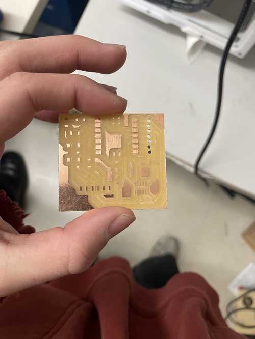
When looking at the bit that I believed was a 1/32’’ bit, I used a 1/16’’ bit instead. I started a new board and made sure that I used a 1/32’’ bit to create it and this was the finished product.

This is the video of my PCB being created
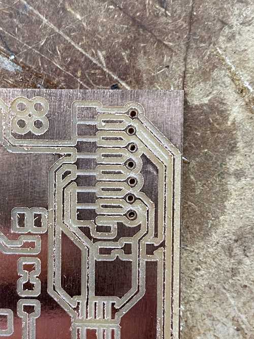
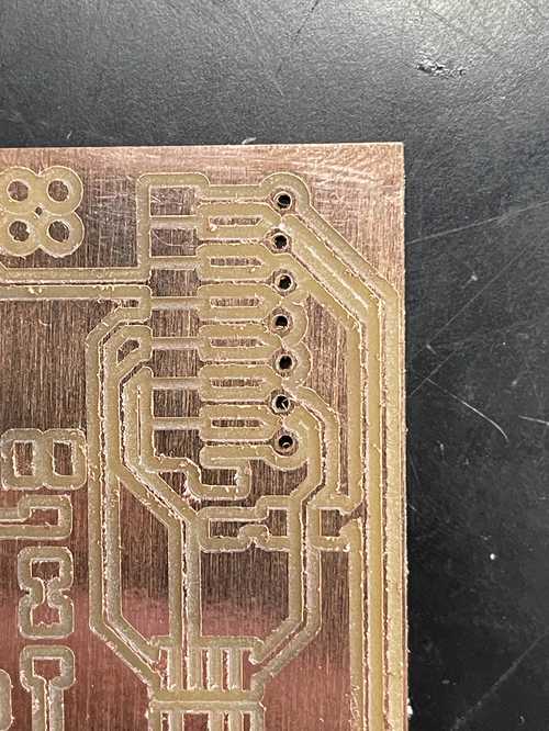
Ryan Zhou pointed out to me that I had traces between my holes and this was a common problem among milling these boards. Upon his advice, I took a box cutter and took out the traces.
Before Cutting Traces
After Cutting Traces
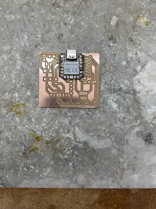
Soldering
Now that my PCB was made, it was time to solder. These are the materials I used to solder.
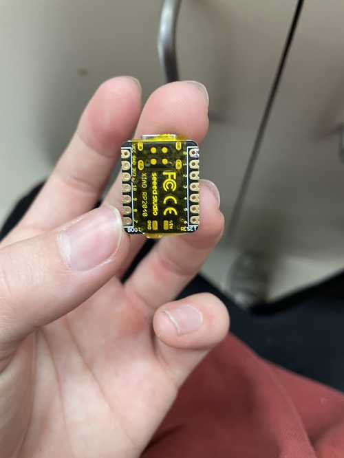
-Seeed Xiao RP2040 Chip -PCB -Conn Header SMD 10 POS 1.27mm -Conn Header SMD R/A 6POS 2.54mm -Tactile Switch SPST-NO Top Actuated Surface Mount Soldering -Blue LED -1K Ohm Resistor -499 Ohm Resistor
While soldering, I used references from Adrian Torres and David Taylor.

I put a piece of kapton tap below my RP2040 so that it didn’t short itself when plugged in.
I then soldered my RP2040 chip by aligning it by soldering one pin then soldering the rest once it was in place.
I then soldered a blue LED coming out of pin 26. I then soldered my 1k Ohm resistor for that blue LED.

I soldered on the button and 2 other resistors and an LED on the bottom of the board

I then soldered the Conn Header SMD 10POS and the final LED. I also soldered the final 2 resistors.

I then soldered the Conn Header SMD R/A

Software
I now needed to download the library for my chip. I added the board URL and other board URL in the Additional Board URL Manager in the Arudino IDE found when you go to boards manager in the Tools dropdown, you can find the software you need by typing RP2040 into the search bar.
I then selected the correct board and port and started to program my chip.
Programming
LED Blinking
To test my circuit board, I used a code given my Richard Shan to blink all 3 LEDs.

After uploading the code, this is the result.
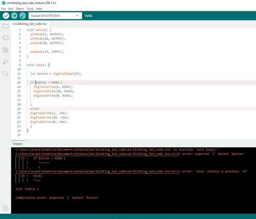
Button-Controlled LEDs
For this, I used the code from Richard Shan to make it so that the LEDs turn on once I press the button. I am very limited when it comes to coding and this process gave me a lot of errors. Luckily, if the error is obvious, Arduino IDE will tell you what you did wrong. This is the first error I got after I put in my first code.
I followed the steps Arduino gave me to fix my code and then my code uploaded successfuly to my board but this time the LEDs just stayed on. This is the code I used

I suspected that my error came from my ‘if’ statement. The first thing I suspected was the ‘=’ sign that I thought checked if the button was pressed or not. I found from this website that the = sign sets the two values equal to eachother. So essentially I was just setting the button to high automatically. To check if the button was pressed or not, I had to use the ‘==’ which checks if the values on either side are equal. Once I uploaded this code it worked!

Downloads
Download all my files for this week here
Reflection
This week went well for me. Since I wasn’t able to come in the first day, I was able to observe the mistakes made that day and make my board without a hitch. I refreshed my knowledge of milling, and also learned basic code for inputs and outputs.