Final Project Documentation
Final Project / Reasoning for Changing
Initially at had a different final project with some work done documented at the end of this documentation.
I decided to change my final project to a tech deck ‘park’ that was built along a conveyor belt so that the ‘park’ was essentially endless. When playing with a tech deck normally, you either had to move with the board or stay confined to a space that stays constant. With this you can go through a changing space while not having to move with the board.
As instructed by Neil, I am going to design my tred similar to how Hideo Oguri’s designed his which meant that I was scrapping my original idea of have a roller chain and gear (which I work on in week 12) to turn in because it would take much more power than Hideo Oguri’s tred.
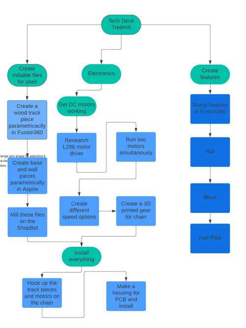
Flowchart
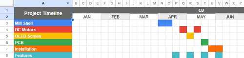
Timeline
Bill of Materials
| Material | Price |
|---|---|
| 1x TETRIX MAX DC MOTOR 39530 | $29.95 |
| 1x L298n Motor Driver | $7.00 |
| 1x ATTINY412 | $0.5 |
| Jumper Wires | $5.99 |
| 1x One-Sides Circuit Board Blanks FR1 | $1.60 |
| .5’’ plywood | $21.80 |
| 6x 18x18’’ Cardstock | $0.19 |
| 8x3mm Magnets | $7.99 |
| Prusament PLA | $29.99 |
| Glossy Vinyl | $19.99 |
| Hex Shaft | $18.09 |
3D Model
First Iteration
Old Version of the Model
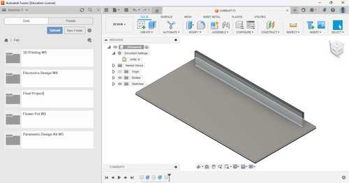
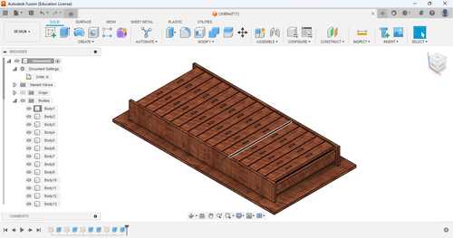
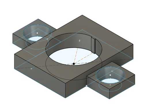
I made a simple 3D model of my final project. I made the design in Fusion360 The design does not include the DC motor or chains but it gives a general outline of what my project will look like. I decided not to use parameters for my 3D design because it was just a 3D model.
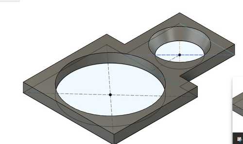
I started out by creating a rectangle sketch and extruding it, this will be the base that everything sits on.

I then created the sides that would hold the tredmill up. I did this by creating construction rectangles on the edges so that I can place the rectangles that I would extrude and create my sides.
I then created the sketch for the wood pieces which would be connected to the chain to extrude. I did this by making one side of the top layer that had an array of rectangles made with the rectangle tool and the rectangular pattern tool and then one side on the sides using the rectangle tool and then mirroring both across the holder.
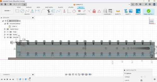
I then extruded the other holder and then the wood that would be on the roller chain.

I then created a new sketch on the roller wood pieces and made three circles, one for the magnet that would allow you to connect new features and the other for the hole that would screw the roller chain onto the wood. I then used a rectangular pattern to copy these circles onto each of the wood pieces.
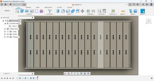
I extruded the magnet circles up a small amount and made it a new body so that I could change the appearance separetly from the rest of the model. I also extruded the roller chain holes down and cut into the wood.

I then changed the appearance of the base to a cherry wood appearance and the magnets to a stainless steel appearance.
You can download my old 3D model here
Final Iteration
With the change in tred for the final project, there had to be a new 3D model made to compensate for the change in design.
The base was the exact same as the other one and most models were already made beforehand so all I had to do was import them and place them correctly. For the skateboard, I used a pre-existing 3D model by leoskates on Thingyverse.

You can download the file as an stl here
Testing Electronics
28BYJ-48 Step Motor
I decided to go with a 28byj-48 Step Motor with a ULN2003 Driver Board at first. Before I finalized any electronics in my final project, I wanted to test the motor to see if I can get it working so I didn’t have any problems with it in the future.
I used an Arduino Uno for testing. Using this tutorial I found out how to wire everything. This required me to get a 5V adapter. It also gave me the code to have it fuction. Once everything was wired, I ran this code that was given to me from the website.
//Includes the Arduino Stepper Library
#include <Stepper.h>

// Defines the number of steps per rotation
const int stepsPerRevolution = 2038;

// Creates an instance of stepper class
// Pins entered in sequence IN1-IN3-IN2-IN4 for proper step sequence
Stepper myStepper = Stepper(stepsPerRevolution, 8, 10, 9, 11);

void setup() {
    // Nothing to do (Stepper Library sets pins as outputs)
}

void loop() {
    // Rotate CW slowly at 5 RPM
    myStepper.setSpeed(5);
    myStepper.step(stepsPerRevolution);
    delay(1000);

    // Rotate CCW quickly at 10 RPM
    myStepper.setSpeed(10);
    myStepper.step(-stepsPerRevolution);
    delay(1000);
}
The integer in the line
myStepper.setSpeed(5);
sets the RPM for the motor. When trying to change this value, I was only able to get an rpm of 20.
I also tested this with a motor mount I designed for the motor.
You can download the file here
When running it with the motor mount, it got so hot that it started to melt the PLA.
Once these tests were finished, I realized that this was not a good motor to use for my project.
TETRIX MAX DC MOTOR 39530
I then decided to try the Tetrix Max DC Motor 39530. This one required an L298n Motor Driver and a 12V adapter. I already have experiments in the past with the motor driver so it made everything pretty simple to hook up. This was the simple code I wrote for it.
void setup() {
  pinMode(11, OUTPUT);
  pinMode(10, OUTPUT);
  pinMode(5, OUTPUT);
}

// the loop routine runs over and over again forever:
void loop() {
    digitalWrite(10, HIGH);
    digitalWrite(11, LOW);
    analogWrite(5, 200);
  }
Once I ran the code, the motor turned and as I changed the analog value on pin 5, the speed would change accordingly.
Switch
Now that I knew my motor was working, I started to test my Honeywell Switch. Using an Arduino Uno and a breadboard with pull down reistors, I was able to make it so that it could detect the inputs on the switch in Arduino Uno using this simple code
void setup() {
  pinMode(8, INPUT);
  pinMode(7, INPUT);
  Serial.begin(9600);
}
void loop() {
  if (digitalRead(8) == HIGH){
    Serial.println("UP")
    delay(1000);
  }
  if (digitalRead(7) == HIGH){
    Serial.println("DOWN")
    delay(1000);
  }
}
Combining them
Now that this was done, I was able to make the speed change depending on the input using this code on an Arduino Uno.
void setup() {
  pinMode(8, INPUT);
  Serial.begin(9600);
  pinMode(7, INPUT);
  pinMode(11, OUTPUT);
  pinMode(10, OUTPUT);
  pinMode(3, OUTPUT);
}

// the loop routine runs over and over again forever:
void loop() {
  if (digitalRead(8) == LOW){
    delay(100);
  } else if (digitalRead(8) == HIGH){
    analogWrite(3, 50);
    digitalWrite(10, HIGH);
    digitalWrite(11, LOW);
  }

  if (digitalRead(7) == LOW){
    delay(100);
  } else if (digitalRead(7) == HIGH){
    analogWrite(3, 200)
    digitalWrite(10, HIGH);
    digitalWrite(11, LOW);
  }
}
PCB
KiCad
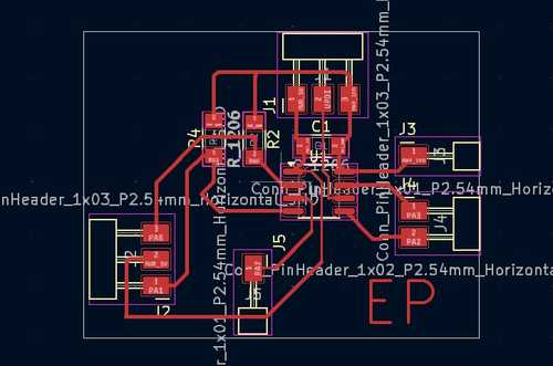
Now I was ready to make the PCB for my Attiny412 in KiCad. I knew what each input and output needed and how to wire them. I made sure that the ground was shared between the Attiny412 and the motor driver.
My shematic included a 1 1x01, 1 2x01, and 2 3x01 Conn Headers, two 10k Ohm pulldown resistors for the input and (obviously) the Attiny412.
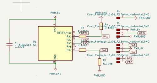
For the tracks, I made them .4mm and I created a rectangular edge cut for it.
You can download the KiCad file here
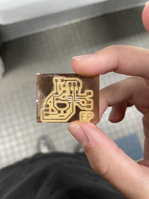
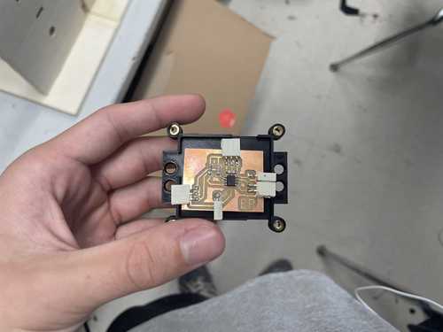
Milling and Soldering
Now that the file was completed, I exported it as a grbl and milled it on out Othermill.
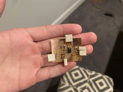
I then soldered each component on. For the singular 1x01 Conn Header, I used hot glue to keep it secure.
Testing and Coding
Now that my pcb was ready, I wanted to test it with my electronics. I used the same code as last time but changed some of the pins according to the Attiny412. This code that I made would end up being the final iteration for my final project.
void setup() {
  pinMode(0, INPUT);
  pinMode(2, INPUT);
  pinMode(3, OUTPUT);
  pinMode(4, OUTPUT);
  pinMode(1, OUTPUT);
}

// the loop routine runs over and over again forever:
void loop() {
  if (digitalRead(2) == HIGH){
    analogWrite(1, 255);
    delay(1500);
  }
  if (digitalRead(0) == HIGH){
    analogWrite(1, 220);
    delay(1500);
  }
  digitalWrite(3, LOW);
  digitalWrite(4, HIGH);
}
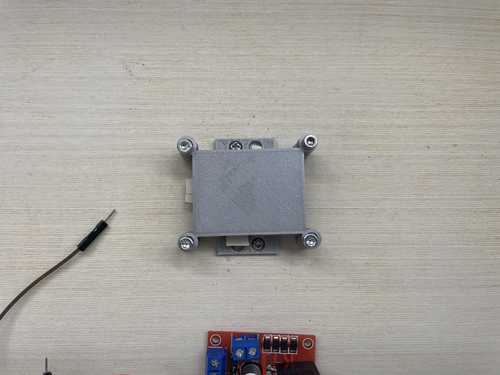
Motor Mount for Tetrix DC Motor
In my tests earlier, the tetrix motor doesn’t exert much heat while running so I knew I was able to make a motor mount out of PLA for it.
Using calipers, I was able to get the dimensions for the shaft diameter and the screw holes. Using those measurements (.47’’ for d-shaft base and .1’’ for the screw diameter), I created parameters so that if a measurement was off, I could change it easily. I designed a motor mount accounting for each hole.
You can download the stl here
I then 3D printed this motor mount on my Prusa Mini.
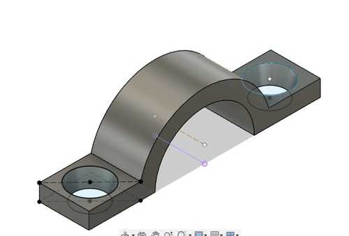
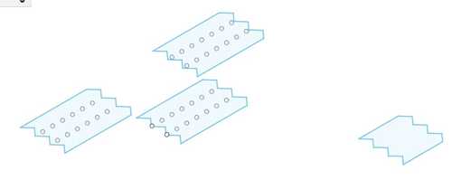
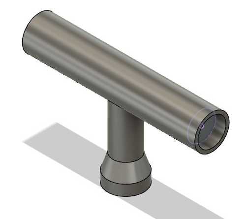
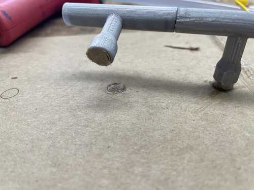
Holders
Now I had to make the part that connected the motor mount to the axle and wheels. To start, I measured the d-shaft of the motor. I got a radius of the d-shaft (.23’‘) and what I thought to be the radius for the circle of the circumscribed hex shaft. Using this, I made 3 different holders. One of them was meant to connect to the motor and hex shaft with an included hole where my bolts would go to mount the motor. The second one was just for the hex shaft to pass through. These two would go paralell on the final product and by the end will have the cardstock wheel connected to both sides. I made sure that the length of them combined was 2’‘. I also included an indent on where the cardstock wheel would go so that it would be easier to attach when the time came.
The last type of holder I designed was for the other side that would go paralell from each other. These would have cylinders that would allow it to mount on the sides of the holder and spin freely.
Shortly after 3D printing these parts, I realized that my hex shaft radius that I made using the circumscribed polygon tool was too big. Upon this realization, I made mini test parts in fusion to see what would be the best radius to fit the hex shaft.
After these tests, I came to the conclusion that the radius of the cirlce for the circumscribed polygon for the best fit was .245’‘.
Once this was determined, I reprinted each part.
Now that each part was printed, I wanted to test it with my motor and hex shaft to make sure everything worked correctly.
It worked!
You can download the stl for the holders here
Base and Mount
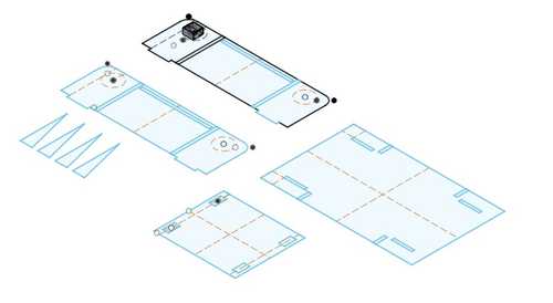
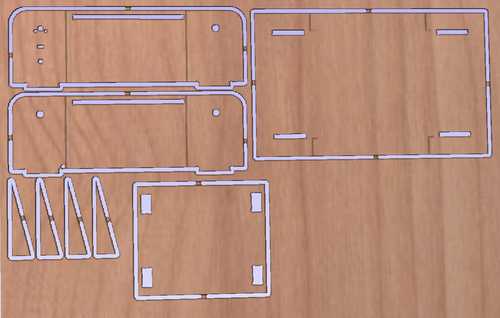
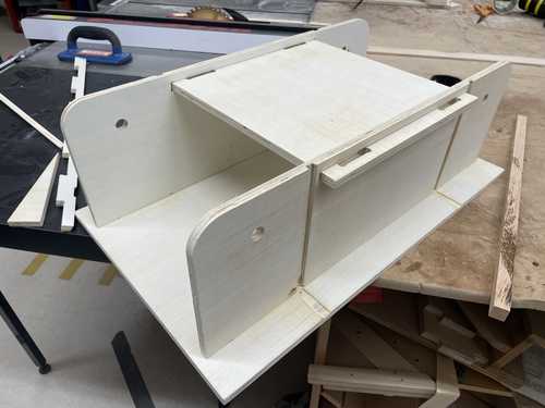
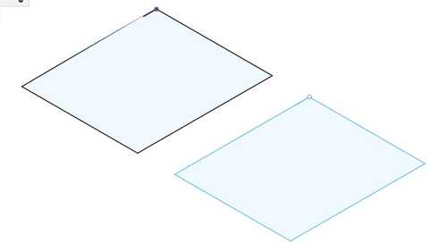
Before I started to design anything for my base and mount, I started to think about the dimensions of the base and mount. I decided that 25’’ long for the mounts were a good size with a 12x12’’ platform for the person to ‘skate’ on was a good size. I decided on a 26x16’’ for the base would be fit to hold everything together. I designed everything as a sketch so I could import the dxf file later into Aspire to create the toolpaths.
With that thought up, I created the outline for the base and mounts. After I created the outline, I started to create the tabs to connect them together utilizing the wood thickness which I measured with callipers(46’‘) and the holes for things such as the motor mount, switch, barrel connector for the 12V power, hex shafts, and platform. For the motor mount specifically, I imported the fusion file I already had to create the holes for the file.
Once everything was designed, I laser cutted the file on cardboard so that I could test and make sure everything was designed correctly.
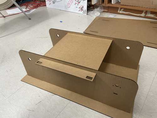
This iteration had a problem, the structure was too unstable which might cause a problem later down the road. To fix this issue, I added triangles meant to be placed on the outside of the mounts so that it would be more sturdy. I also made lines for a pocket I will make for the triangles so that they fit correctly.
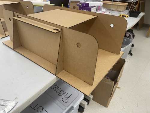
I was also able to test to see how my electronics fit and they all fit well so I was ready to take the file in Aspire.
You can download the dxf for this file here
Aspire
I then exported the fusion file as a dxf and imported it into Aspire. I joined each of the lines using the join tool in Aspire because the importing a dxf Fusion file sometimes makes some lines not join so I had to manually join the ones I wanted to be joined. Once this was done I dogboned tabs
The Bits I used were 3/8’’ Compression Spiral and 1/8’’ Straight. I then made five toolpaths, one for 1/8’’ bit Pockets all the way through, one for 3/8’’ bit Pockets all the way through, one for 1/8’’ .05 inches down, one for 3/8’’ .05 inches down for the support placing, and a 3/8’’ Compression Spiral bit for a Profile to cut out each peace fully.
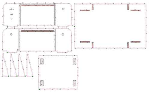
I then ran each of these toolpaths in Aspire’s toolpath viewer to make sure everything looked correct.
Since everything looked good in the 3D view, I was ready to mill.
You can download the Aspire file here
Milling
To mill, I exported the toolpaths for our ShopBot. I then took the plywood I was using and attached it to the bed using brads
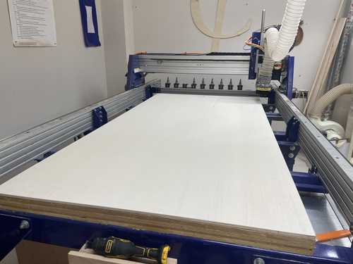
Once this was done, I was ready to mill.
This was the result of the mill.
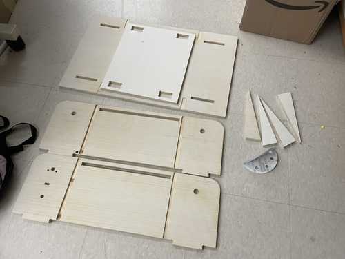
Once I had got them off the mill, I sanded each of them using the orbital sander.
Unfortuneatly, the file was not designed perfect and there were a few things I had to do before the pieces were finished.
The first was that the part where I put the triangle parts were not milled all the way through so I had to sand the ends down so that it would fit nicely.
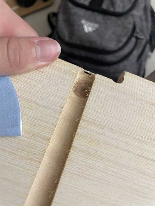
The second issue was that the platform didn’t fit so I took a P100 grit sandpaper and sanded it down until it could fit
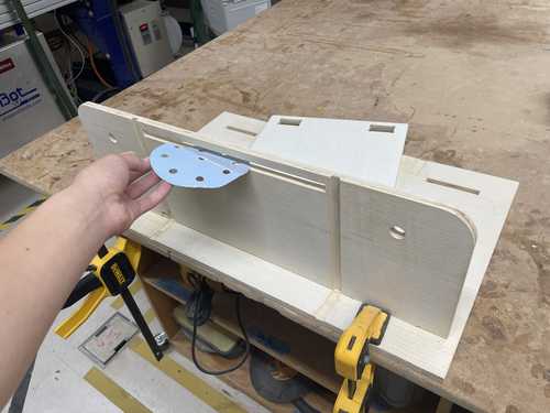
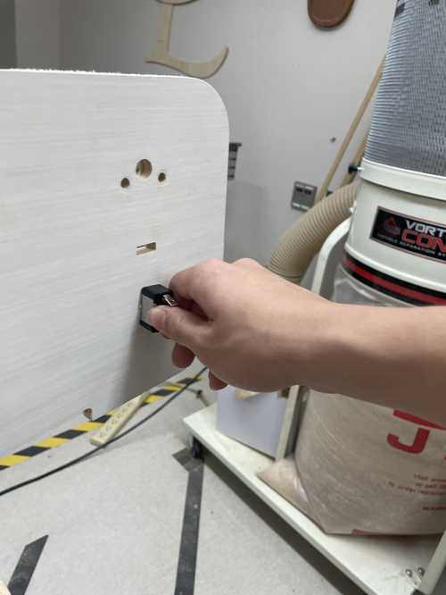
The last was that the Honeywell switch didn’t fit correctly.
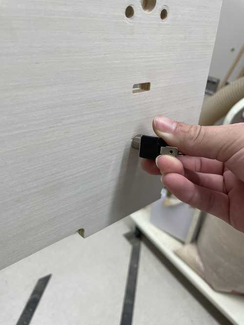
To fix this, I got a 12.7mm drill bit and used it to create a larger hole where the switch would fit.
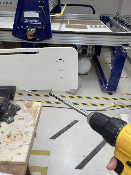
This allowed the switch to fit correctly.
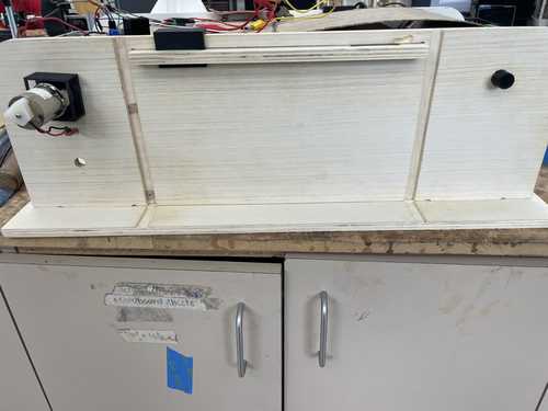
Now that each problem was adressed, I was able to completly assemble the shell.
Electronics Cases and Other Holders
L298 Motor Driver Case
For the L298 Motor Driver case, I used this case designed by WellOiled on Thingyverse. I put it together using M3*10 bolts.
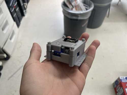
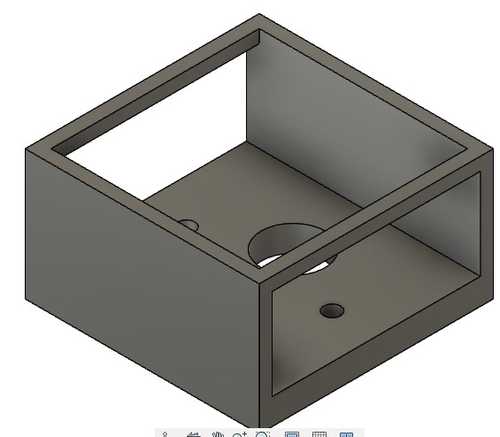
PCB Case
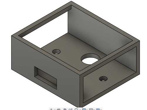
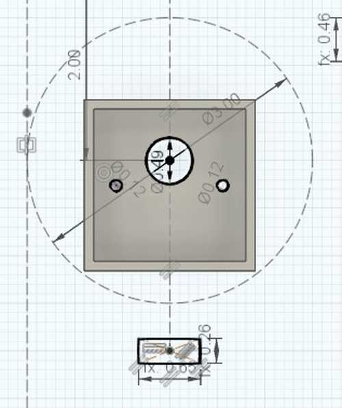
The PCB Case I had to design myself. Using the L298 Motor Driver case from above as a reference, I designed a top and bottom for the case. For the dimension of the PCB, I used callipers. For holes for the Conn Headers to poke out from, I used callipers to measure the position on the case and put holes there accordingly.
I put holes on each corner for the top to be bolted onto the bottom with heat-set inserts. I also created screw holes for wood screws on the edges of the case to secure it to the base. To do this, I used calipers to measure the size of my wood screw (M2x6; .19’‘) and made a circle above it slightly larger. I then used the loft tool to make a hole through the case.
You can download the stl here
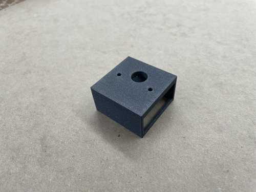
I then printed both the top and bottom and put heat set inserts into the bottom part of the case.
I then was able to put it completely together using th M3*8 bolts.
The color of the case is differnt in both pictures because I did a messy job putting in the heat-set inserts which made it so that I coouldn’t put the bolt through. I had to reprint and put the heat-set inserts in again.

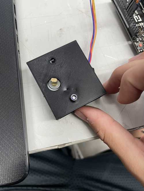
Switch Holder
For the holder for the Honeywell switch, I used callipers to find the switch diameter (.42’‘) and desinged a simple 3D print that would keep it poking out allowing the user to change speeds. I used the same type of wood screw to mount it for this one so creating the screw hole was the same as the process for the pcb case.
You can download the switch holder stl here
Barrel Holder
For the barrell holder for the 12V adapter, I used callipers and found teh daimeter of the barrel connector (.395) and made a spot for the wood screws using the same process as the pcb case.
You can download the barrel holder stl here
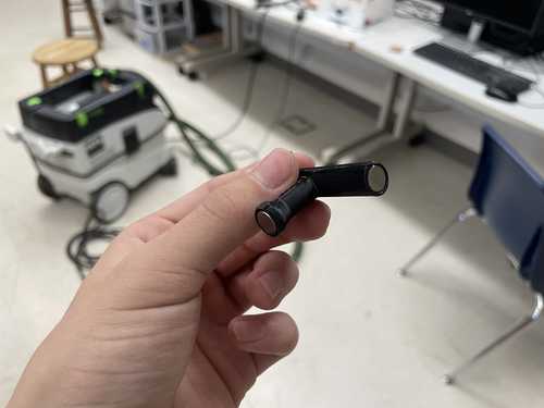
Cardstock Wheels
I decided to make my wheels out of cardstock. In my Base and Mount sketch earlier, I had already determined that I wanted my wheels to be 3’’ in diameter. To find the length I would need to get this diameter I just found the circumfrence of a 3’’ circle using (2πradius). The width had to be the exact distance across to each holder. Because the distance from one edge of the mounts to the other was 12’‘, I was able to find the distance with this calculation (( 12 in - 2 in ) - ( ( 2 * 0.455 ) * 1 in )). The 2’’ accounts for the holders and the 2*0.455 acounts for the thickness of the wood.
Download the dxf file here
I then exported this file as a dxf and lasercutted it on our Epilog M2 Laser Cutter.
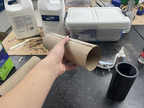
Rolling the cardstock perfectly without a guide proved to be a struggle. To fix this, I decided to print a cylinder with a diameter of 3’’ that I used as a guide to create the cylinder. This was very easy to make, just a shelled cylinder with a height of 6’’ and a diameter of 3’‘
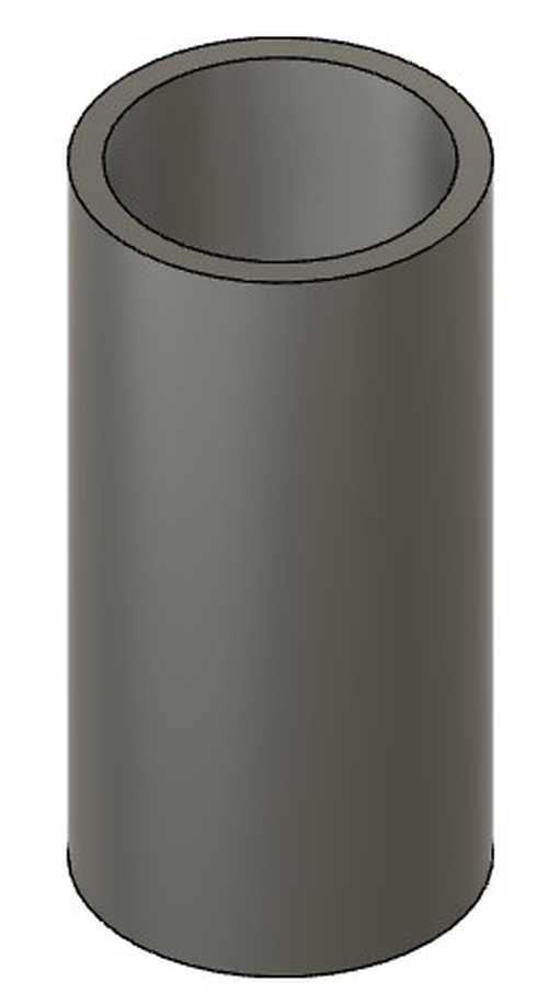
You can download the stl here
Now that the guide was printed, I made the cardstock wheels by rolling them and then gluing it with super glue.
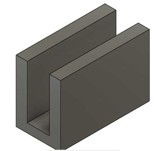
Stoppers
In my platform, I intentionally left holes for stoppers that I designed so that there was no way for the platform to move once the stoppers were in. This allowed me to take on and off the platform as I wished while still making it stable when I put the stoppers in.
To desing the stoppers I just need the wood thickness (.455’‘) and then I made the thickness of each side to fit the holes I put into the platform.
You can download the stl for the file here
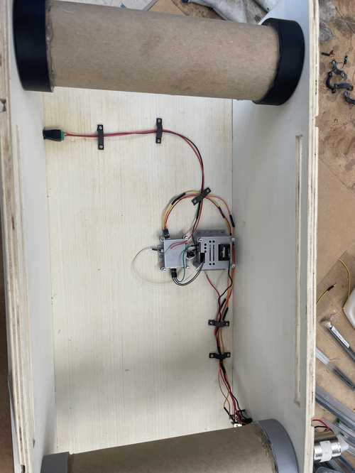
Assembly
Now that I had all my parts (excpet for the tred which I will expound upon later) I was ready to assemble the Tred Deck.
The first thing I did was install the motor mount using M3*10 bolts along with the holders. I then glued on the cardstock wheels to each pair of holders.
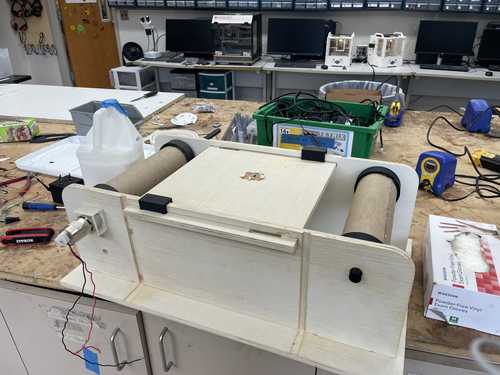
Once this was done, I installed everything inside the base using wood screws and new wiring for placements.

I then designed some wire loops with holes for M2*6 wood screws for wire organization in Fusion360 and them printed them.
Download the Wire Loop stl here
I then used the wire loops to help organize my wiring.
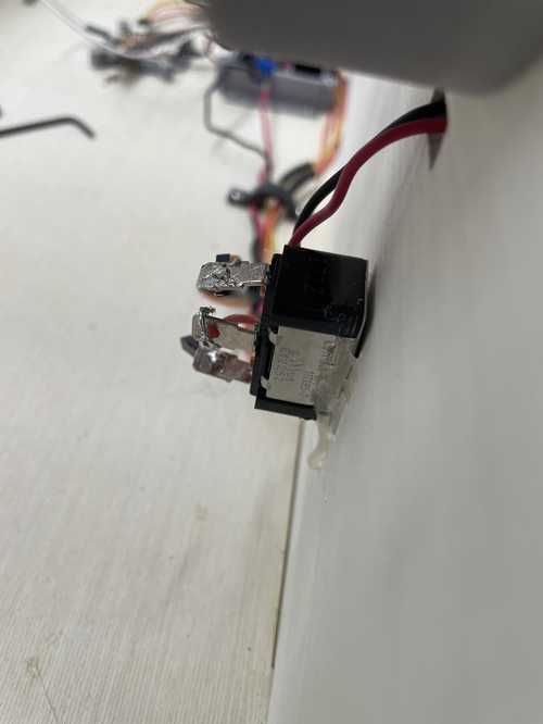
I made a small mistake when soldering the wires onto the Honeywell Switch which made it seem as though my code was not working but in reality I just didn’t solder the power to the switch correctly.
Once all the electronics were installed, it was time to do the tred.
Tred
Originally I made this file for my tred. Which I later laser cutted
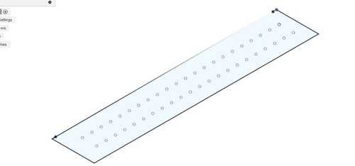
The idea was to make it so that the spots where the magnets were to be placed were scored. This would make my magnet placing more precise which it needed to be because one wouldn’t be able to ‘extend’ their features if the magnets weren’t spaced correctly. This was easily done using the rectangular pattern in Fusion360

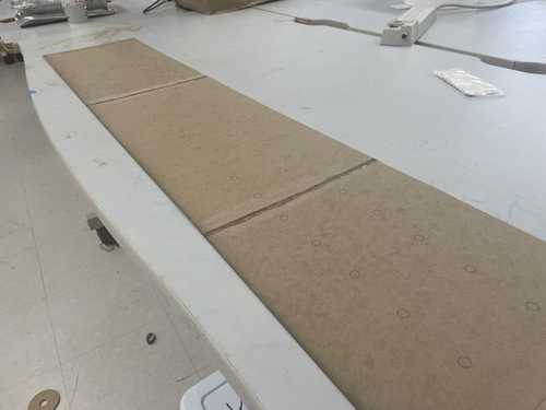
Since we only had 18x18 Cardstock in the lab, I planned on gluing 3 sheets together with butt joints then laser cutting them. The first few attempts, the tred came out short which made me have to remake it until I got the right size.
Even when I did get the right size, the tred kept breaking when I was wrapping it.
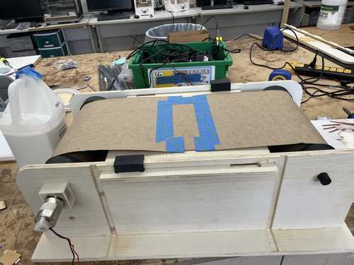
I was then given an idea by Garrett Nelson to make each connecting tred piece have teeth so that there were more surface area which meant it was harder to break. So I designed a new file which had each individual piece of tred teethed for each 18x18’’ cardstock. Lining up the circles for the magnets was a little bit more tricky. All I had to do was line each tred up and then do the rectangular pattern for the spacing of each circle.
I then lasercutted this file and glued each piece onto eachother.

This tred was much more robust and was able to wrap around the wheels without breaking (I still haven’t had a problem with it so far).
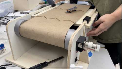
Now the tred was turning and it was ridable! The last thing this project needs is…
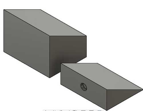
Features!
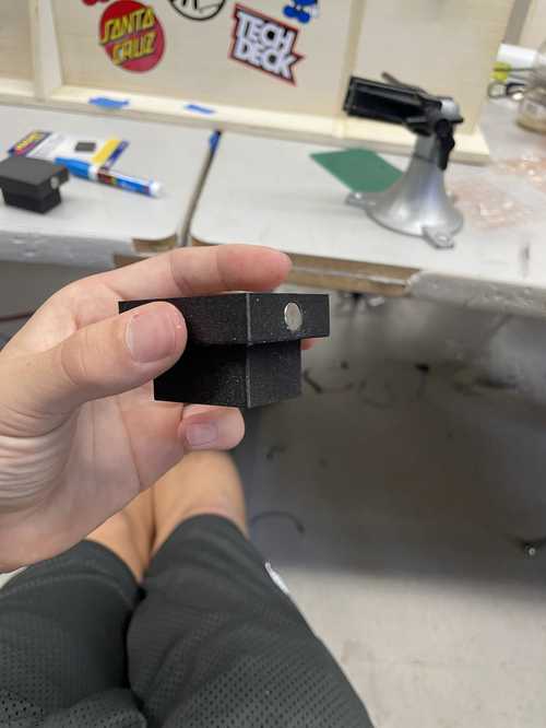
By this time, I have made three features for the Tred Deck. The rail, the box, and the ramp. Each of these features and become longer if you add the same or a compatable piece next to it on the trail (for example the ramp which can only be made longer if the next ‘step’ is the one your placing next to it). This is done through magnets on the tred and the feature which allows you to move each feature to your liking.
Designing the rail and box were similar. Both were symmetrical pieces which required a magnet hole on the bottom to connect it to the tred and a magnet hole on both sides to allow one to connect the pieces amongst each other to make them longer. I made sure to design it parametrically in case I find better magnets for my purpose. For me, I was using 8x3mm magnets so that was the parameter for the diameter and height of my magnets.

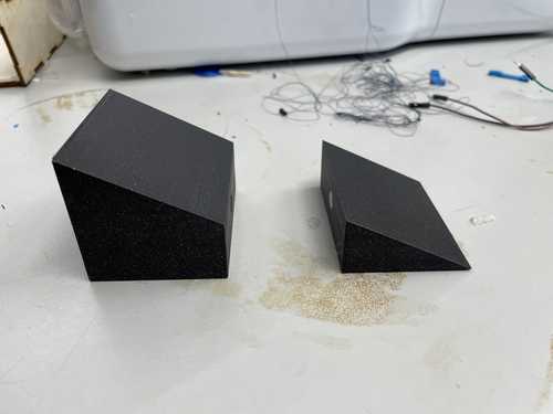
The ramp was a little differnt because it was symetrical. I also wanted it so that you can increase the ramp height so that meant for this one feature I had to make two models. One for the starting ramp and a connecting ramp which extended the height of the ramp. Each ramp required a magnet on the bottom and a magnet on one side to connect to each other.
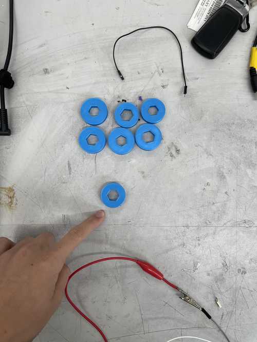
I then 3D printed each of the features and super glued the magnets onto each feature. I had to be careful with how I was gluing the magnets because if I misglued them then the features will repel each other instead of connecting.
I also glued some magnets onto the tred so that the features can be put on!
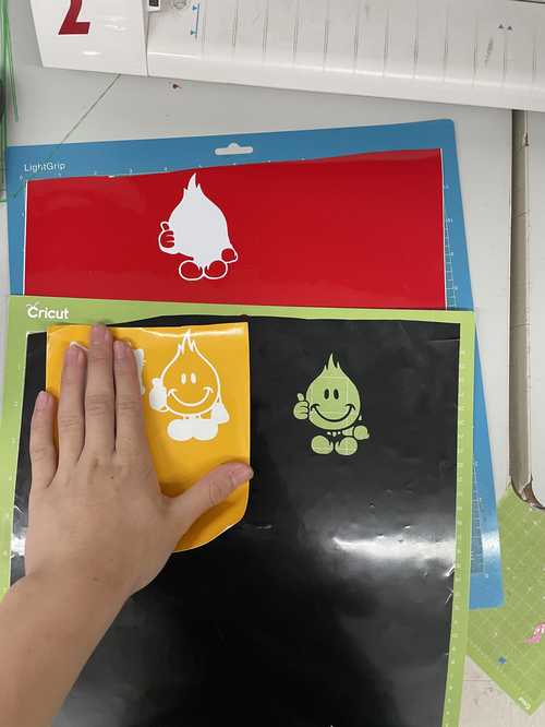
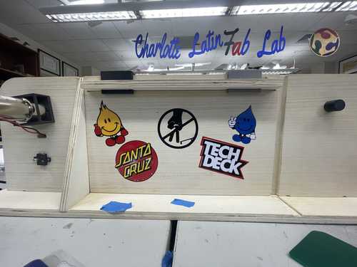
Vinyl Stickers
To add a little bit of aesthetics, I decided to put some vinyl stickers on my final project relating to skateboarding/fingerboarding. Here are all the images that I used.
On the computer connected to our Silhouette Cameo, I uploaded the pngs and traced the bitmap on the edge. I would cut the Vinyl on each sticker and then weed the unneeded parts out. I would then stack the correct colors on top of each other using transfer tape and a squeegee to create the sticker. I would then take the compelted sticker and put it on the Tred Deck.
Completed Project
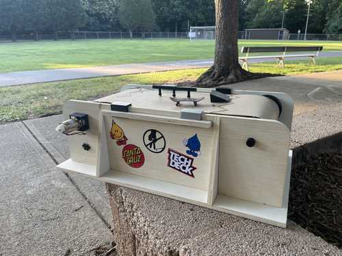
I would like to thank all of my instructors here at the Charlotte Latin FabLab for supporting us throughout the entire way by giving us encouragment, guidance, and belonging. I would also like to thank my hardworking peers for encouraging and helping out along the way.