11. Input devices
This week I worked on an input device for my final project. I decided on a potentiometer which is an input that allows you to control resistance which can allow you to decide the power that goes to an output (such as motors for my project).
Failures with the ATtiny412
To read my input, I wanted to have the Attiny412 read the voltage going into it from the potentiometer. I look online to see if it was possible and I got mixed answers that didn’t answer my question directly. I decided to just go straight into it and try uploading code that would print the voltage going into your microcontroller (which was controlled by my potentiometer). I decided that I would use the board that I created for my output week because it had every pin I needed. I soldered some wires to what I thought at the time were the GND (Green), Input (Red), and Output (Orange) pin.

I attached it to my pcb. I used by quenntorres for programming the Attiny412.

I ran the ReadAnalogVoltage example on Arduino and changed the pin to 4. I uploaded the code and nothing happened when I looked into the Serial Monitor. Confused, I started to move the potentiometer around a little and it started to smoke. I realized that I had wired my potentiometer wrong which was causing the smoke. I found a photo showing me how my specific potentiometer should be wired by etechnophiles on pintrest.

While I was fixing this, I was told that the Attiny412 does not have the ability to communicate with the Serial Monitor on Arudino, this meant I could not use that chip for what I was trying to achieve.
RP2040
I decided that I would try an RP2040 to achieve this task. I took an RP2040 chip and used a breadboard to test to see if it would work. I wired the GND to GND, Input to 5V, and Output to A0. I ran the ReadAnalogVolatage Example and it worked!
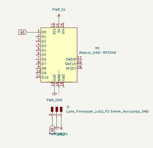
Now it was time for me to design a simple board for this week. I came to the conlcusion that all it needed was 3 Conn Header 2.54 mm and an RP2040. This is the schematics for the board in KiCad
I wired this one manually making the traces .4 mm. I then made a rectangular edge cut.

I then milled and soldered this board together

I wired the pot accordingly to the schematics and ran the code on the RP2040 and it worked.
Group Project
Our group project can be found here.
Downloads
My downloads for this week can be found here
Reflection
This week I took very easy (due to recovering from machine week), although it was still somewhat helpful. I’m planning on using a poteniometer for my final project so this week still contributes to my final project.