7. Embedded Programming
This week I worked on assessing different types of processors (RP2040, ATtiny412), testing out bootloaders, and programming/uploading various input/output centric codes. You can access all of my files here.
Assignment
individual assignment:
-
write a program for a microcontroller development board that you made, to interact (with local input &/or output devices) and communicate (with remote wired or wireless devices)
-
extra credit: use different languages &/or development environments
-
extra credit: connect external components to the board
group assignment:
-
browse through the data sheet for your microcontroller
-
compare the performance and development workflows for other architectures
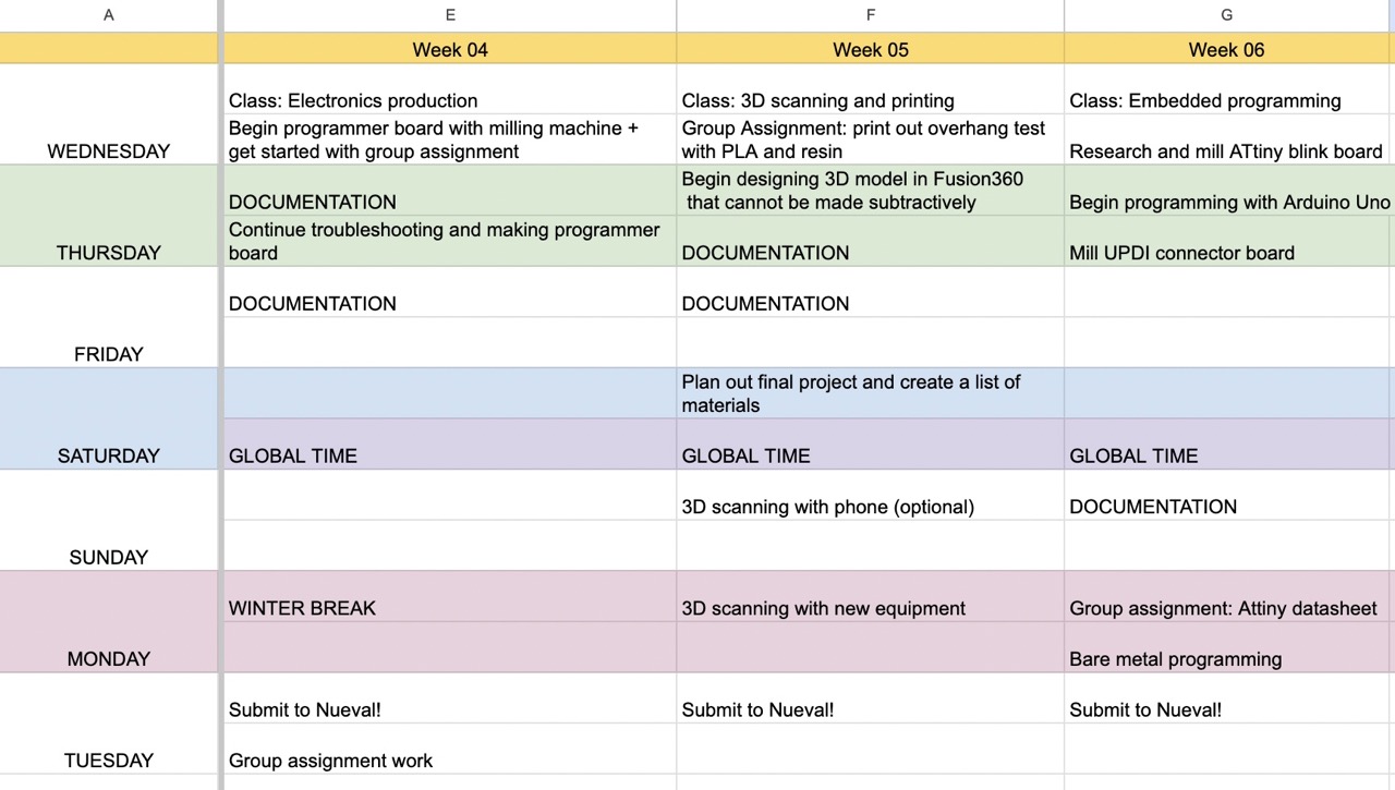
Here is my weekly schedule:
Datasheet
For the group assignment, Connor, Kabir, and I looked through the ATtiny412 Datasheet to become more familiar with the specs of the microcontroller, including its pinout, features, configurations, etc. For more information on the datasheet and group findings, reference the full documentation here.
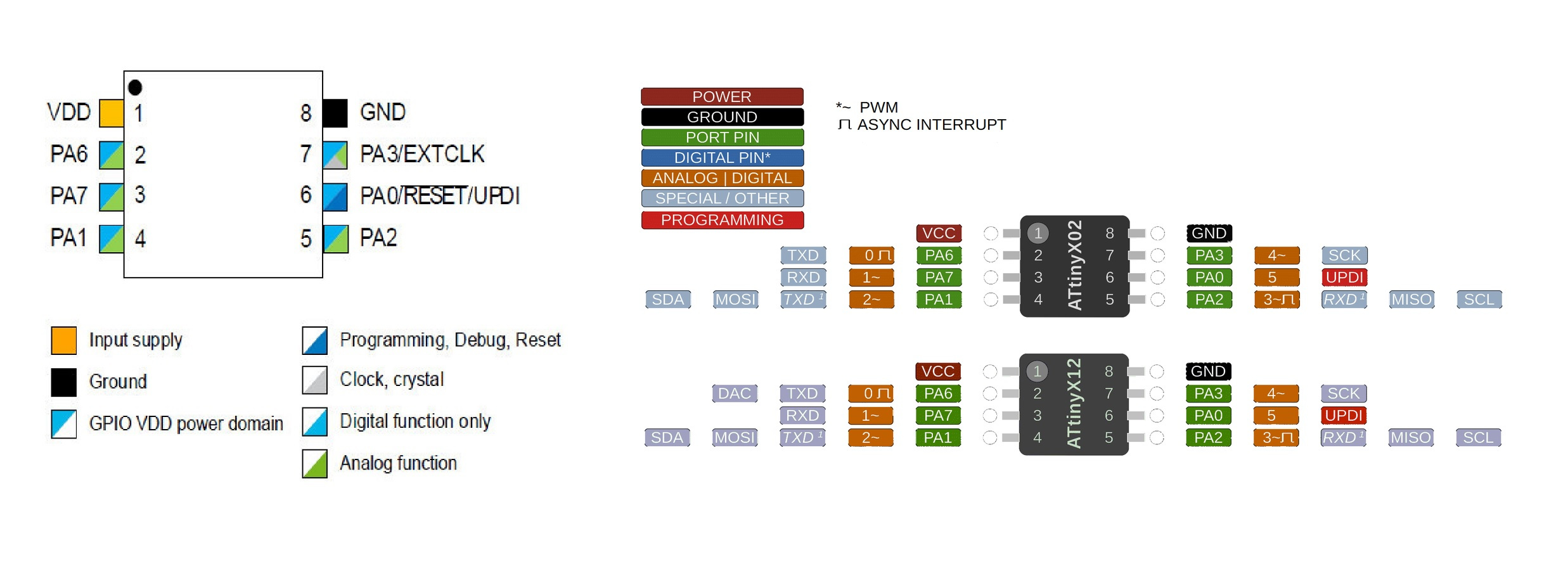
ATtiny412
Referenced from Adrian Torres’ documentation, I began investigating the uses and features that the ATtiny412 offered. According to this website, the ATtiny412 is a microctroller using the 8-bit AVR process with hardware multiplier, running at up to 20MHz and 4KB Flash, 256B SRAM and 128 bytes of EEPROM in a 8-pin package. This week’s goal was to mill out and program a simple break-out board for the ATtiny412; we would first start by uploading the code through Arduino, before experimenting with the QuenTorres board we designed during Week 4. I worked alongide Connor Cruz and Kabir Nawaz during this process.
Here’s what the microcontroller includes:
-
8 pin package
-
Digital pins: PA0, PA1, PA2, PA3, PA4, PA5, PA6
-
Analog pins: PA1, PA2, PA3, PA4, PA5, PA6
-
GND: Ground
-
VDD: Voltage
-
-
Two internal clocks 16 and 20 MHz
-
4 KB Flash Memory
-
128 B EEPROM
-
256 B SRAM
-
Maximum voltage: 6V; minimum voltage -0.5 V
UPDI - Unified Program AND Debug Interface
UPDIs are a Microchip proprietary interface for external programming and on-chip debugging of a device. In other words, it provides a specific pin to connect the blinky board with the ATtiny412 and the Arduino Uno microcontroller.
For this assignment, we’ll be using a firmware called jtag2updi that allows a microcontroller like Arduino to host a target board as a programmer.
                                            V_prog                 V_target
                                              +-+                     +-+
                                               |                       |
 +----------+          +---------------------+ |                       | +--------------------+
 | PC       |          | Programmer          +-+                       +-+  Target            |
 | avrdude  |          |                     |      +----------+         |                    |
 |       TX +----------+ RX              PD6 +------+   4k7    +---------+ UPDI               |
 |          |          |                     |      +----------+         |                    |
 |       RX +----------+ TX                  |                           |                    |
 |          |          |                     |                           |                    |
 |          |          |                     |                           |                    |
 |          |          |                     +--+                     +--+                    |
 +----------+          +---------------------+  |                     |  +--------------------+
             JTAGICE MkII                      +-+     UPDI          +-+
             Protocol                          GND     Protocol      GND
This is a good representation of how our connection looks from the programmer to the target board. Adapted from this site.
Milling the ATtiny412 Blinky Board and the UPDI
ATtiny412 Blink Board
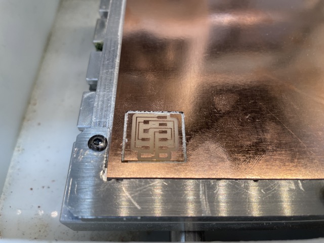
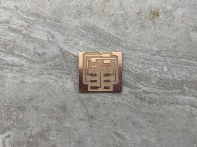
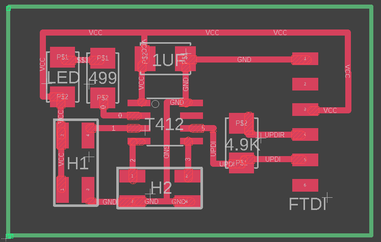
We first had to find a file to mill and program. After looking at previous year’s documentation and searching the internet for brd/gerber files, we found Adam Harris’s ATtiny412 Blinky Board. We downloaded the newer version, found here, and brought the file into Bantam.
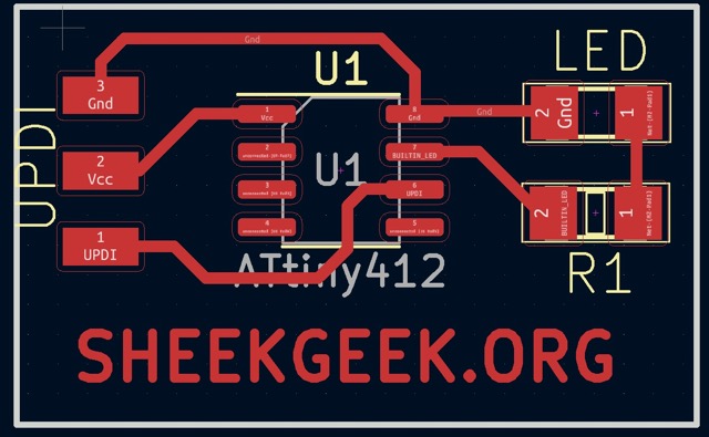
Here is the schematic.
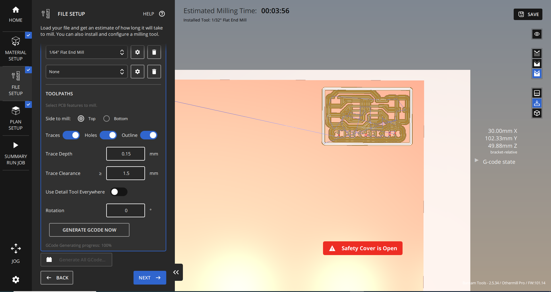
This file was slightly different than the ones provided by Neil in the Fab Academy schedule, but we found that it served essentially the same purpose. Upon importing the file, we set material dimensions, z-offset, and probed the z- axis. We used a 1/64” flat end mill for the traces and a 1/32” flat end mill for the outline. To find more documentation on the milling process, refer to my Electronics production week.
There were no major issues during the milling process, besides a slight error with the z-axis probing. There was likely debris underneath the FR-1, resulting in inconsistent material thickness values. Instead of removing the board, as we would do normally, we simply changed the plan offset and probed until it returned a normal value (1.7mm - 2.0 mm range).
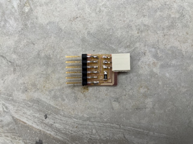
UPDI Connector Board
There was not a provided milling file for the UPDI, so we had to manually create one through Mods, a CAD software that allows users to create milling designs from .png files. Kabir uncovered this method initially and shared his findings, as none of us were that familiar with Mods.
I first went through the Fab Academy schedule for this week, and found the .png under serial UPDI-3 (in the in-system development list).
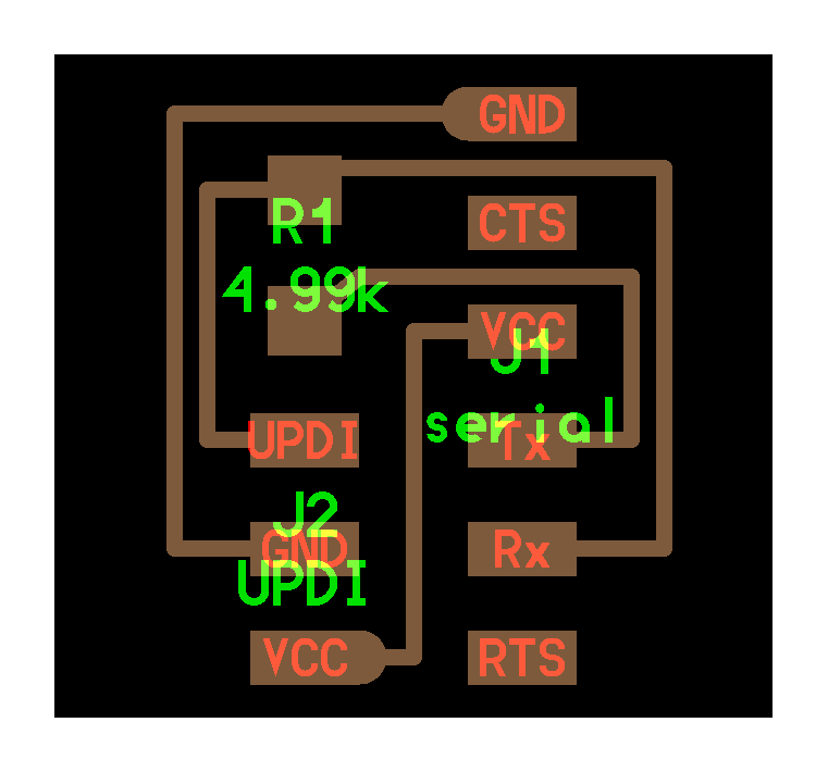
In Mods, I went from Right click > programs > open program > PCB under the othermill list > select .png from files and pulled the traces design.
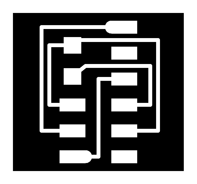
I had to complete the design generation process twice–first time with the traces, and second time with the exterior outline.
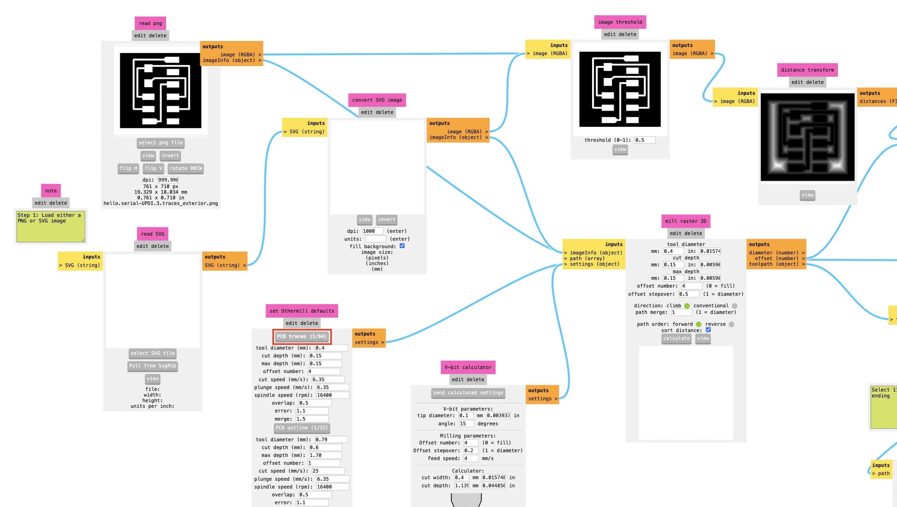
I toggled the on/off button next to the files option. This just ensures that the file is auto-saved.
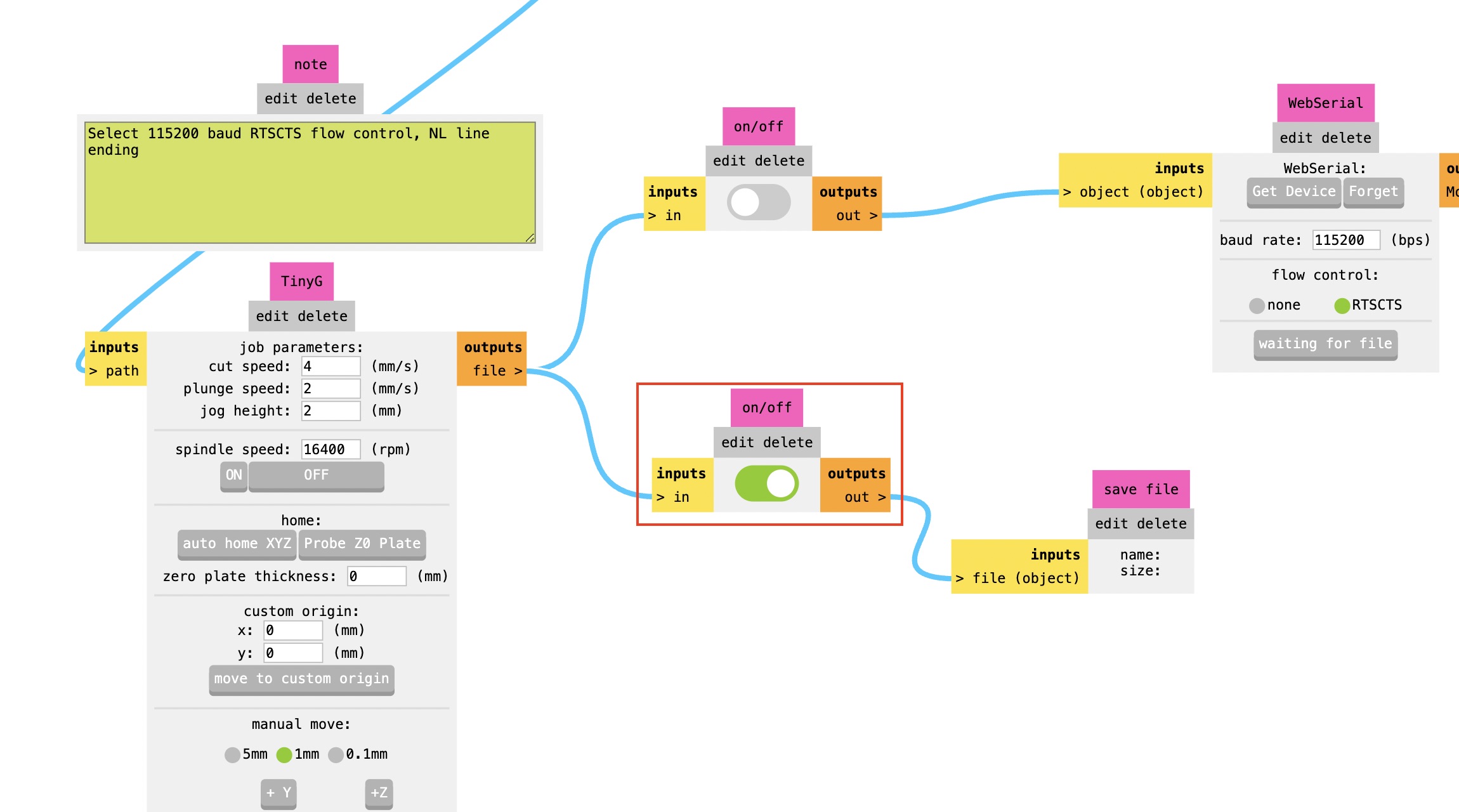
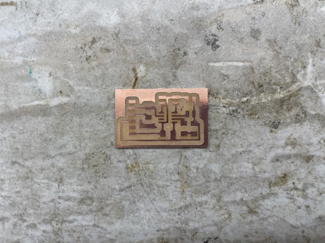
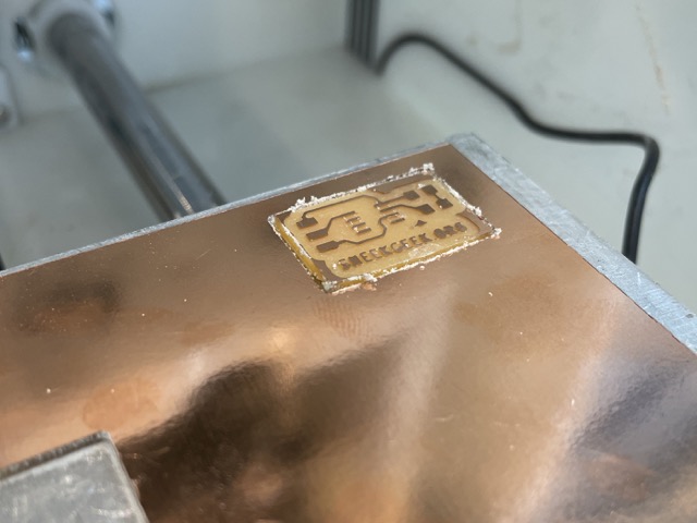
When I clicked the Calculate button, it created a .nc file that could be imported into Bantam! I set up the same setting configurations again with the 1/64” flat end mill and the 1/32” flat end mill and milled two boards.
Soldering
Components for the ATtiny412
| Component | Quantity |
|---|---|
| ATtiny412 | 1 |
| Blue LED | 1 |
| 6-pin SMT male header (FTDI) | 1 |
| 4.99Ω 1206 resistor | 1 |
| Milled PCB | 1 |
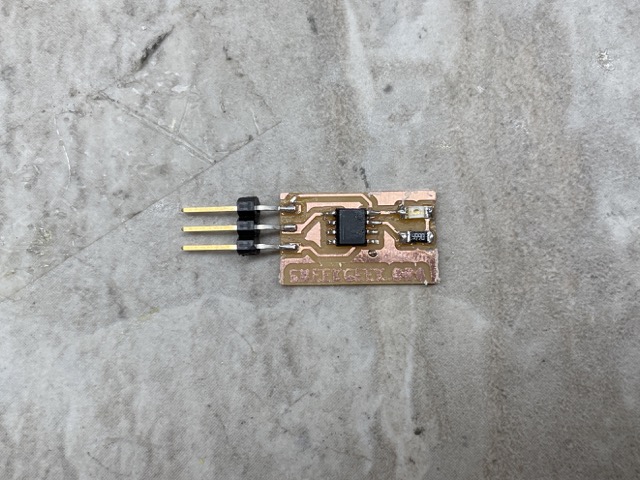
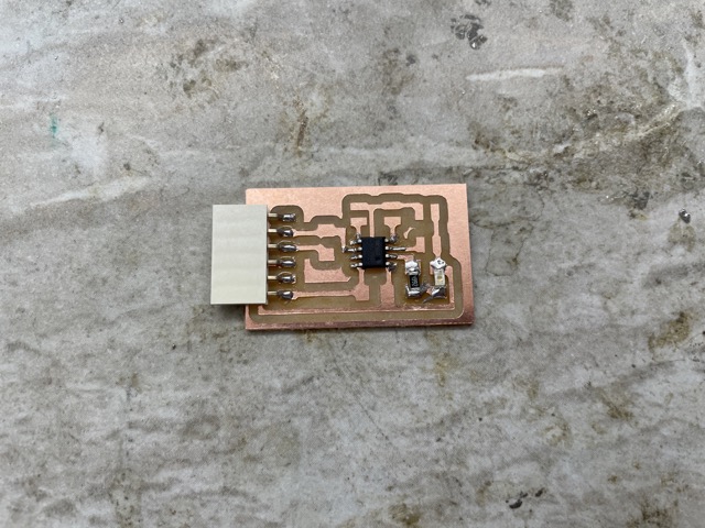
For the 6-pin SMT header, I used a pair of wire cutters to cut off 3 pins so that it could fit on the board.
To solder the ATtiny onto the board, I first examined its polarity, searching for an indicative dot or symbol on the board. I ended up using a microscope to view it better.
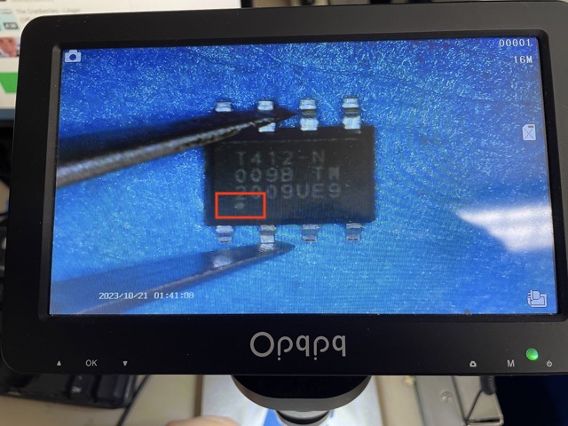
Here is the dot on the ATtiny412, which should be aligned with the first pin.
Because I had practiced surface mount soldering during Electronics production week, soldering these components was fairly straight-forward. I similarly used solder paste because it was the easiest to use with smaller components, such as the ATtiny.
Components for the UPDI
| Component | Quantity |
|---|---|
| 6-pin SMT male header (FTDI) | 1 |
| 6-pin SMT female header | 1 |
| 4.99Ω 1206 resistor | 1 |
| Milled PCB | 1 |
For the 6-pin SMT female header, I used a pair of wire cutters to cut off 3 pins so that it could fit on the board.
Arduino IDE Setup
Programming ATtiny412 With an Arduino Uno Microcontroller
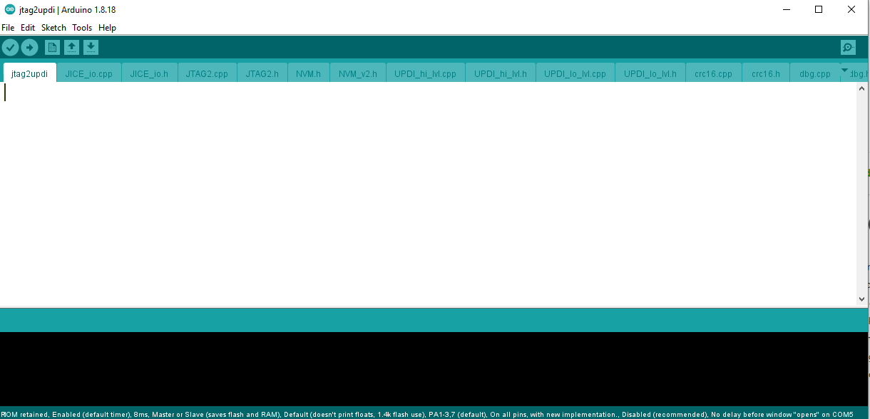
I started by opening up Arduino IDE version, specifically the 1.8.18 version. I opened and uploaded the empty jtag2updi program onto my Arduino Uno microcontroller. This ensures that the microcontroller acts as a programmer for the ATtiny.
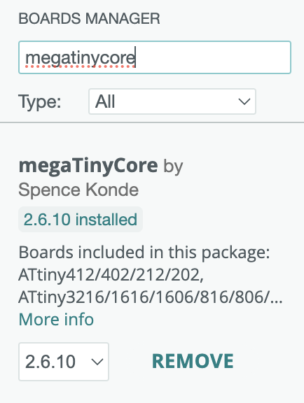
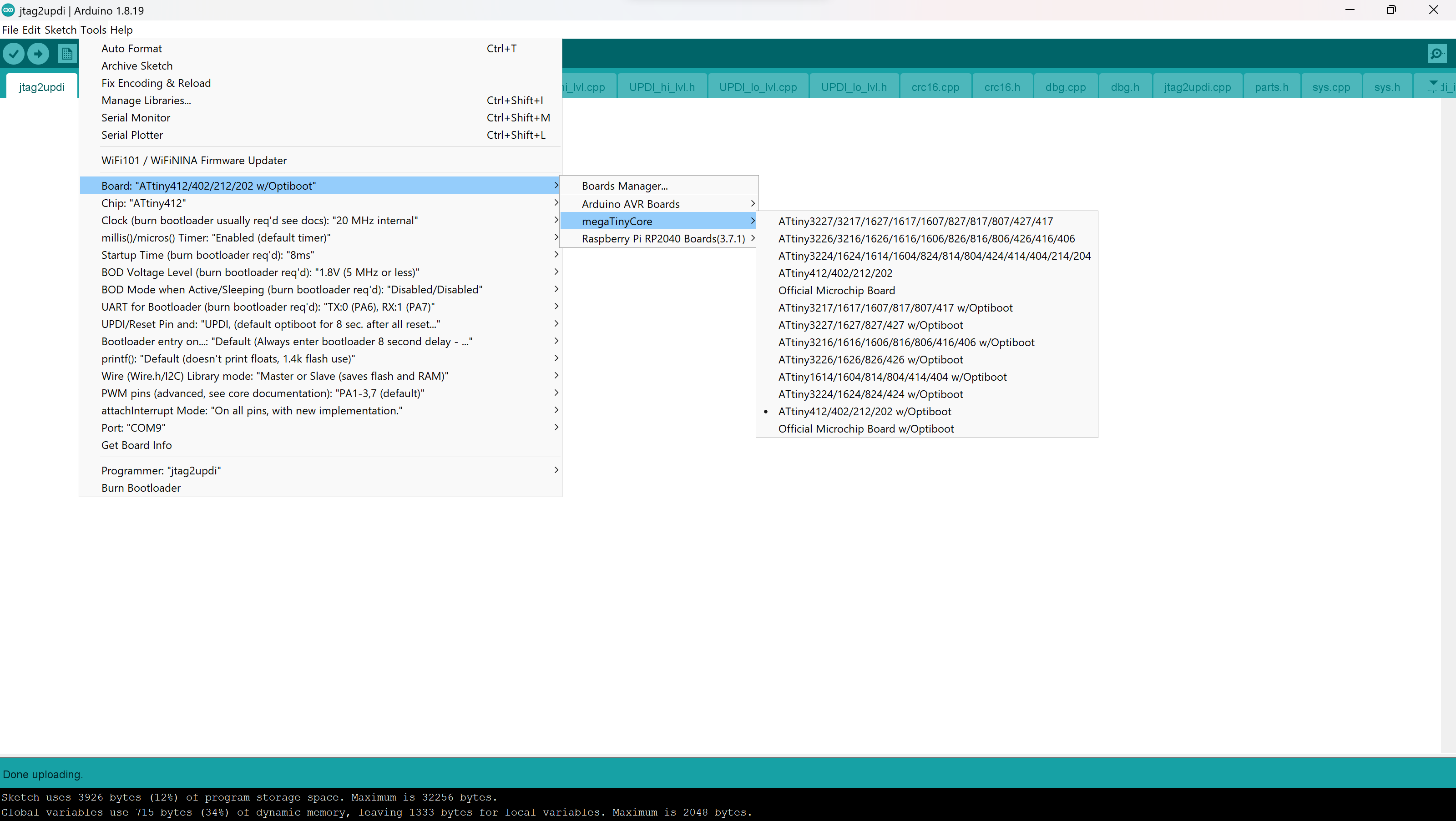
The next step was to install megaTinyCore, a library that makes Arduino IDE compatible with serial UPDI programming. I did this by going from Library Manager > typing in megatinycore > install.
Then, following the ATtiny412 pinout, I used three female-to-male jumper wires to connect the blinky board directly to an Arduino Uno. I connected GND to GND, VDD to the 5V pin, and the UPDI pin to pin 6 (this is designated as the UPDI pin).
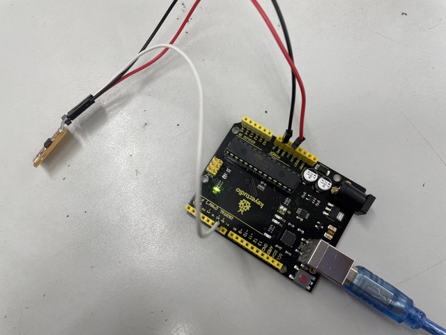
GND, VCC, and UPDI connections to the board are shown with black, red, and white wires, respectively.
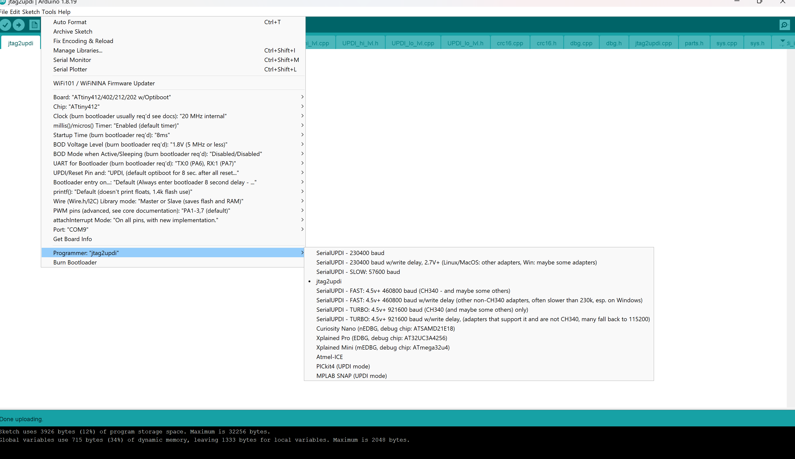
I opened up the example blink code and began making modifications to define a specific pin. I set the pin to pin 4 because thats the pin the LED was connected to on the blink board. I selected ATtiny412 under megaTinyCore for the board and jtag2updi as the programmer.
Here is my code:
int LED = 4;
// the setup function runs once when you press reset or power the board
void setup() {
  pinMode(LED, OUTPUT);
}

// the loop function runs over and over again forever
void loop() {
  digitalWrite(LED, HIGH);   // turn the LED on (HIGH is the voltage level)
  delay(1000);                       // wait for a second
  digitalWrite(LED, LOW);    // turn the LED off by making the voltage LOW
  delay(1000);                       // wait for a second
}
Programming Blink ATtiny412 With the QuenTorres - Failed Attempt
Next, I tried setting up my ATtiny412 with the QuenTorres, using the UPDI connector component and three female-to-male jumper wires. When I uploaded my program, however, there were immediately upload issues, in which the code didn’t reach my ATtiny blink board.
Problem 1
The first problem was that the output returned
pymcuprog.pymcuprog_errors.PymcuprogError: UPDI initialisation failed
which made me question if there was a secure connection between the target board and the RP2040. To test whether this theory was true, I used the same connector and RP2040 alongside Collin Kanofsky’s target board (that still contains the ATtiny). When I uploaded the code, there were no software issues, and the LED blinked accordingly. I tested other combinations as well, such as using his RP2040 and my target board. After checking the wire connections and comparing them to the schematic one last time, I turned to the internet for help. Several websites, including the QuenTorres documentation, suggested that I first install pymcuprog before uploading.
So I ran
pip install pymcuprog
in my terminal. The documentation then prompted me to locate my hex file in my terminal and input the following:
pymcuprog write -t uart -u /dev/cu.usbmodem13F809833 -d attiny412 -f ATtinyblink.ino.hex --erase --verify
the /dev/cu.usbmodem13F809833 refers to the specific port my board was connected to; it will be different for everyone.
Although the first output looked hopeful, it returned the same error as before.

Seeing as this was a recourring response to this error, I was more certain that my issue was hardware-related.
Problem 2
An additional issue with my target board was that it heated up unexpectedly when plugged in. Everytime I tried to upload a code, although it never went through, the board would get a little hotter. This indicated that there was a constant and substantial power supply that was provided to the board.
Programming ATtiny412 With the QuenTorres - 2nd Iteration
During my second iteration, I soldered and tested an alternate, older board made by Dr. Harris. Collin Kanofsky and Evan Park previously tested this board, so I was confident it would work.
The soldered components were essentially the same as before, except for the 3-pin male header, which was replaced with a 6-pin female header.
I followed the schematic of this alternate board to figure out how to connect it to the UPDI board.
As for the code, the ATtiny412 was connected to the LED through pin 0. I adjusted the program accordingly in Arduino IDE:
int LED = 0;
// the setup function runs once when you press reset or power the board
void setup() {

  pinMode(LED, OUTPUT);
}

// the loop function runs over and over again forever
void loop() {
  digitalWrite(LED, HIGH);   // turn the LED on (HIGH is the voltage level)
  delay(1000);                       // wait for a second
  digitalWrite(LED, LOW);    // turn the LED off by making the voltage LOW
  delay(1000);                       // wait for a second
}
This message popped up in the console:
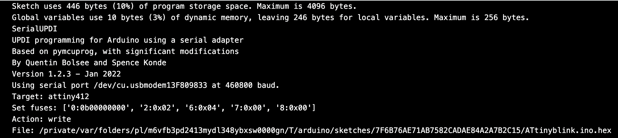
This board blinked as intended, meaning it was a success!
Although this meant that I had successfully programmed an ATtiny412 through an Arduino Uno and an RP2040, I was still curious about my initial board. I decided to re-mill the file again and observe any notable differences between the working and the faulty board.
Here we go again..
The only difference I saw was that Collin’s board had an ATtiny412 with a small divot in the corner, as opposed to a printed design.
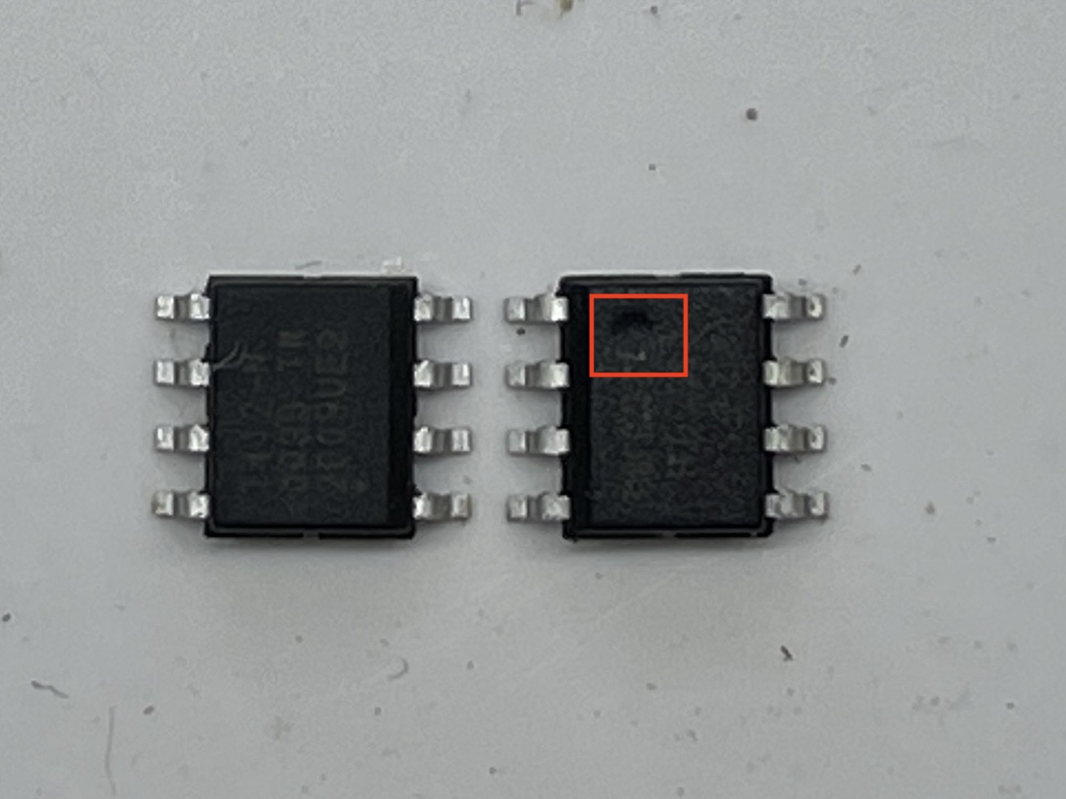
I didn’t know if this truly affected the board, as all of the ATtiny’s came from the same bin in the lab. However, when I soldered (same components as before) and tested the board with the program, I found that it worked!
Programming Basic Inputs/Outputs with QuenTorres
For the second half of this week, I wanted to work a bit more on the QuenTorres and test out some inputs/outputs. My biggest goal for this week is to start program different types of capacitive touch sensors and/or transistors to turn on an LED.
int buttonstate = 0;

void setup() {
  pinMode(26, OUTPUT); // initializing the LEDs
  pinMode(1, OUTPUT);
  pinMode(0, OUTPUT);

  pinMode(27, INPUT_PULLUP); // initializing the tactile switch
  Serial.begin(9600);

}

void loop() {
  buttonstate = digitalRead(27); // returns whether button is on or off
  if (buttonstate == HIGH) {
    // turn LED on:
    digitalWrite(26, HIGH);
    digitalWrite(1, HIGH);
    digitalWrite(0, HIGH);
    Serial.println("The LEDs are on!");
  }
  else {
    // turn LED off:
    digitalWrite(26, LOW);
    digitalWrite(1, LOW);
    digitalWrite(0, LOW);
    Serial.println("The LEDs are off!");
    }

}
Here’s what it looks like when uploaded:
Bare Metal Programming
Resouces used:
Bare Metal Programming with the Arduino Uno
Traditionally, when we program a microcontroller with softwares like Arduino IDE, we use RTOS, or real-time operating system. It runs on top of hardware and provides a simple framework for users to program. On the other hand, bare metal programming involves programming directly on the hardware, without the use of an operating system or middleware. In this case, users write code that interacts directly with the hardware, accessing registers and memory locations to control system behavior. Bare metal is mainly preferable over RTOS at times because of its efficiency in reducing processing time.
First, I followed this video, which was helpful in introducing the purpose of bare metal programming with Arduino Unos as an example. He first defined what registers were, which are essentially a place in the RAM (random access memoery) that has a special purpose for the microcontroller. It is represented by 8-bits/binary.
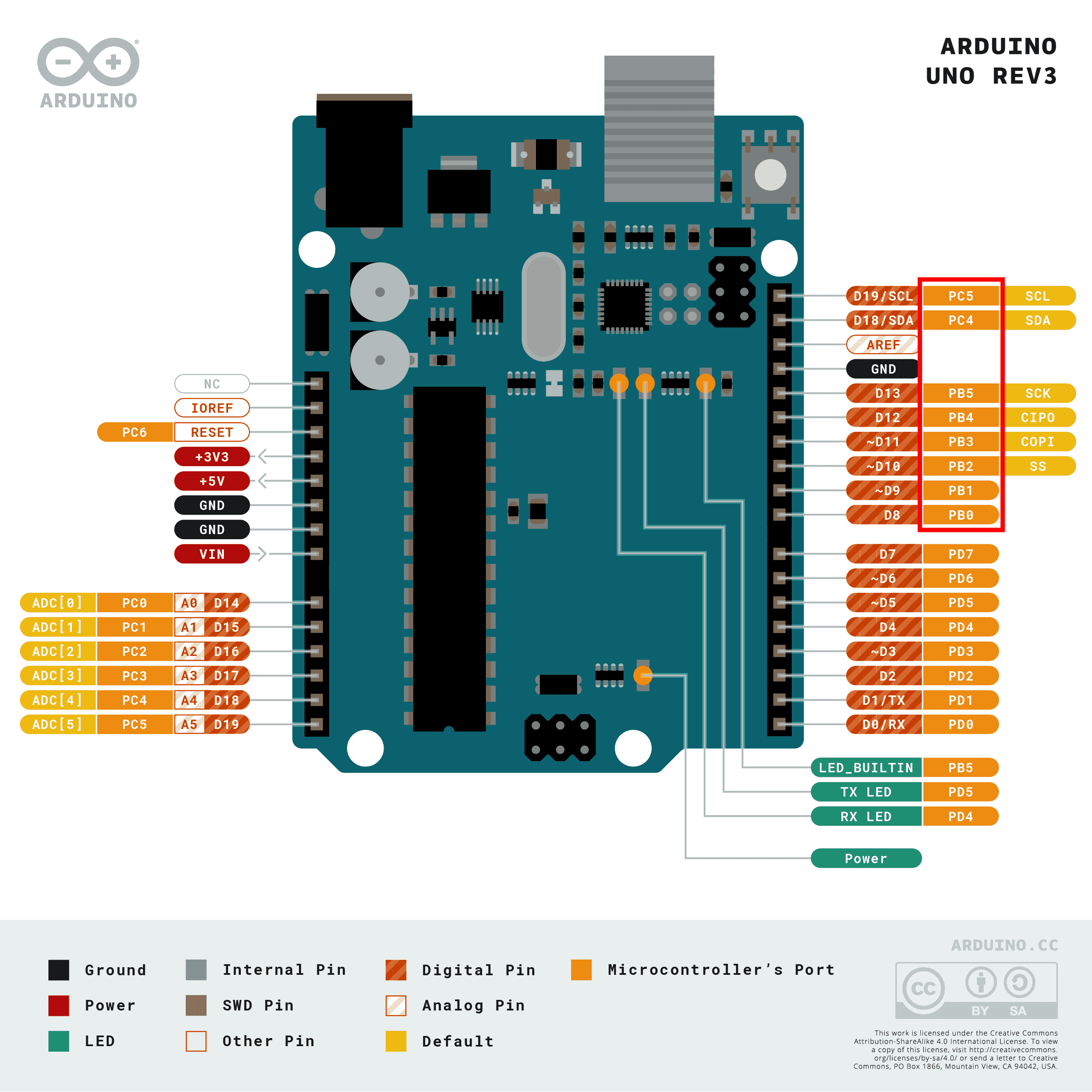
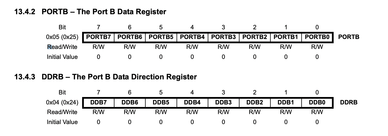
Here is also the Port B data register and the Port B data direction register, found on the ATmega328P datasheet.
Instead of referencing the Arduino pins (ex. D0 or D5) and using the DigitalWrite() function, I’m instead looking at the second column that begins with PB. PB5, which is located in the same place as Arduino pin 13, refers to Port B, bit 5.
The register will look something like this when the LED is set to HIGH (just a visualization):
bit: 0 - 0 - 1 - 0 - 0 - 0 - 0 - 0 = 32
pos: 7 - 6 - 5 - 4 - 3 - 2 - 1 - 0
Bit five is represented by 32 in binary. Every other number is represented by a 0.
Now, when we want the LED to turn on, we can reference PORTB and assign the value to 32. Likewise, when we want to turn the LED off, we define it as 0.
void setup() {
  pinMode(LED, OUTPUT);
}

// the loop function runs over and over again forever
void loop() {
  PORTB = 32;   // turn the LED on (HIGH is the voltage level)
  delay(1000);                       // wait for a second
  PORTB = 0;    // turn the LED off by making the voltage LOW
  delay(1000);                       // wait for a second
}
Next, he also explains how we can replace pinMode() with DDRB, which similarly determines the pins (later referenced) as either input or output. If its written as 1 (represented by binary again), the pin is configured as an output. If its written as 0, the pin is configured as an input.
Here’s what the code looks like now:
void setup() {
  DDRB = 32; // configures pins as an output
}

// the loop function runs over and over again forever
void loop() {
  PORTB = 32;   // turn the LED on (HIGH is the voltage level)
  delay(1000);                       // wait for a second
  PORTB = 0;    // turn the LED off by making the voltage LOW
  delay(1000);                       // wait for a second
}
I built a simple circuit with an LED and a low-value resistor and uploaded the code.
Bare Metal Programming with the ATtiny412
Now, it was time to implement these practices with a different board. Before starting, I looked into C++ bitwise operators to better grasp how it will play into my program.
| Operator | Description |
|---|---|
& |
Bitwise AND operator |
| |
Bitwise OR operator |
~ |
Bitwise Complement Operator |
<< |
Bitwise Shift Left Operator |
>> |
Bitwise Shift Right Operator |
&= |
Bitwise AND operator and assignment operator |
|= |
Bitwise OR operator and assignment operator |
To begin programming my ATtiny, I first noted some key differences between the Arduino (ATmega328P) and my board:
-
The chip used is the ATTINY 412 instead of ATMEGA328
-
Pins are referred to as PA instead of PB, indicating that the register is PORT A

This is taken from page 105 and specifies that the PORT A as an register for pin configuration.
- Following others’ documentation, I found that defining the pin and the input/output could be achieved with different commands (ex. many used
PORTA.DIRinstead ofDDRA)
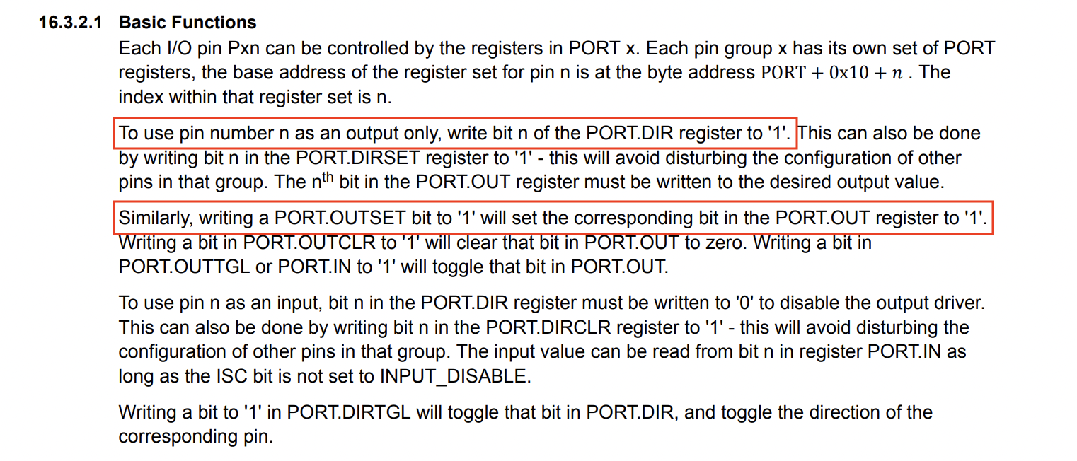
Page 108 of the ATtiny datasheet specifies this command change.
- Additionally, instead of defining the binary value based on the bits, many used
PIN3_bm, for example.
As mentioned previously, the pin that my LED is connected to on my blink board (original version) was pin 4, so I looked for the PORT A equivalent. After finding that it was PA3, I made modifications to my code. I followed Wan-Ting Hsieh’s 2020 documentation, which clearly outlined the command changes.
Here is my modified code:
void setup() {
  PORTA.DIRSET |= PIN3_bm; // initializing the LEDs

}

void loop() {
  PORTA.OUT |= PIN3_bm; // turns the LED on

  delay(1000);
  PORTA.OUT &= ~PIN3_bm; // turns the LED off

  delay(1000);

}
I uploaded this code to my ATtiny412 with the same set-up and settings as before and it worked!
Reflection
I found this week even more confusing, time-consuming, and overall challenging than Electronics production week. The biggest struggle is always the indefinite troubleshooting – I never know if something will truly work or not, and most times, I’ll spend hours figuring out how to fix it. Nonetheless, when it all works out, it feels like magic.
On a brighter note, I enjoyed learning how to use the Arduino Uno as a UPDI programmer. Additionally, though I minimally explored this topic, bare metal programming was also interesting! Overall, I learned a lot about things I didn’t know even existed, and I’ve refined applications of previous weeks (ex. milling + converting .png to .nc in Mods) in doing so! It’s safe to say I’m scared and excited for future weeks.