8. Computer controlled machining
This week, I explored the safety procedures for our ShopBot PRSalpha, ultimately designing and assembling a piece of furniture. You can access all of my files here.
a week with an abundance of mistakes, but a good lesson for the future!
Assignment
individual assignment:
-
make (design+mill+assemble) something big (~meter-scale)
-
extra credit: don’t use fasteners or glue
-
extra credit: include curved surfaces
-
group assignment:
-
do your lab’s safety training
- test runout, alignment, fixturing, speeds, feeds, materials, and toolpaths for your machine
Concept Definitions
Because I have never used the large ShopBot (I’ve only used a medium sized version) before, this week introduced a lot of new definitions that I am unfamiliar with. Fortunately, Dr. Taylor and Mrs. Vaneza, a furniture manufacturer at iFurniture and a fellow instructor, gave a comprehensive introduction to the different concepts we had to know. Additionally, I learned a lot about joints through the 50 Digital Joints project, which explained how to connect components together without fasteners/adhesives. Here are some of the major takeaways I had (including notes from Neil’s lecture too!):
Resouces:
Definitions:
-
Feed rate: The distance the cutting tool travels during one spindle revolution; (inches per min)/(RPM x number of flutes)
-
Down cut: direction of the flutes go downwards from left to right; pushes chips down, creating a cleaner surface
-
Up cut: direction of the flutes go up from left to right; pushes chips up, creating a rougher finish
-
Roughing: Roughing removes bulk amount of excess material from workpiece in every pass; high feed rate
-
Finishing: Finishing improves surface finish; low feed rate
-
Pocketing: Tool routes a defined area to certain depth and does not cut through the material
-
Stepover: amount of tool overlap between passes; the smaller the stopover percentage, the finer the finish (greater tool path overlap)
-
Chamfer: special chamfer tool in the shape of a “v” cuts into material leaving an angled edge
-
Profile: follows a line of an individual part; a profile cut follows a closed shape to a specified depth; kerf can impact your cut
-
Outside profile cut: calculates a profile tool path around the outside of selected vectors
-
Inside profile cut: calculates a profile tool path around the inside of selected vectors
-
Depth of cut: how deep each individual machine cutting pass should be to reach the cut depth
Design Constraints
Material Thickness
Early on, I learned that the material thickness isn’t always accurate to the marketed value, so I first took a pair of calipers to measure the thickness of the wood sheets.
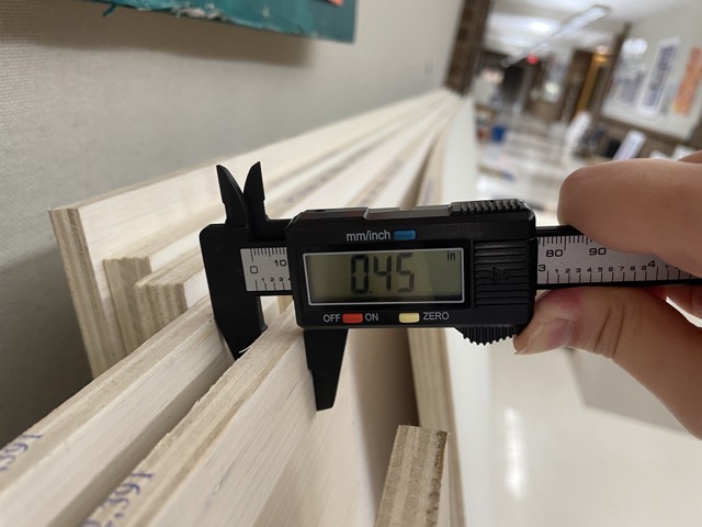
As you can see, the .5” wood is closer to .45”.
Additional Constraints
Here were some other constraints I had to keep in mind while designing my file:
-
There were two plywood thicknesses (.5” and .75”), and certain thicknesses were more optimal for specific furniture types
-
All designs were to fit on one sheet of plywood, approximately 48” x 96”
-
Tabs are necessary to keep the wood in place during pockets and profiles
-
Don’t go too deep with each pass, as it can damage the bit
Initial Idea: Designing a Flower Stool
For my initial idea, I wanted to produce a piece of furniture that could be both portable and visually appealing. Originally, I was going to CNC the legs and the main table frames for my final project, but that didn’t directly involve joints (I wanted the table to completely fold, meaning I would have to use hinges connecting the legs to the table). I began looking on pinterest for some inspiration, and I found this flower stool:
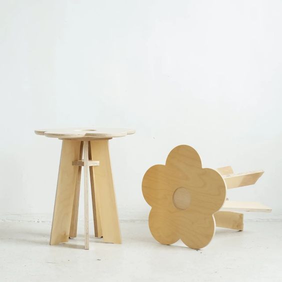
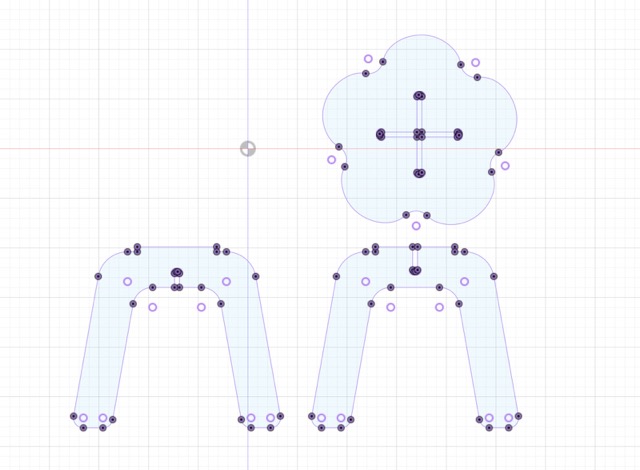
I liked this concept, so I began mapping out dimensions. After looking at some of the stools that previous graduates had designed, I figured that I wanted a smaller stool, around 1.5 ft tall. I began sketching the flower surface and the two legs in Fusion360. I used parameters to define the wood thickness (.5”) and the slot length. Additionally, I filleted the bottom of the legs for stylistic purposes. Additionally, I took tolerance/offset into consideration to ensure that my components could still fit well together.
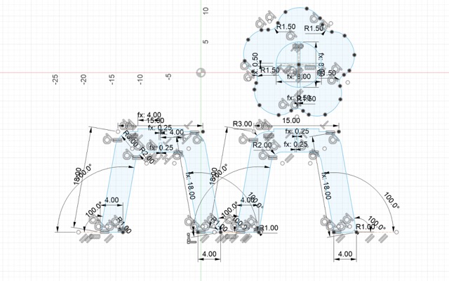
I extruded this sketch by the material thickness value, .5”.
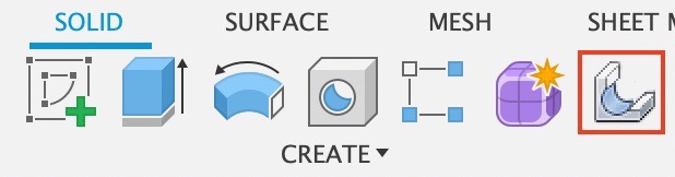
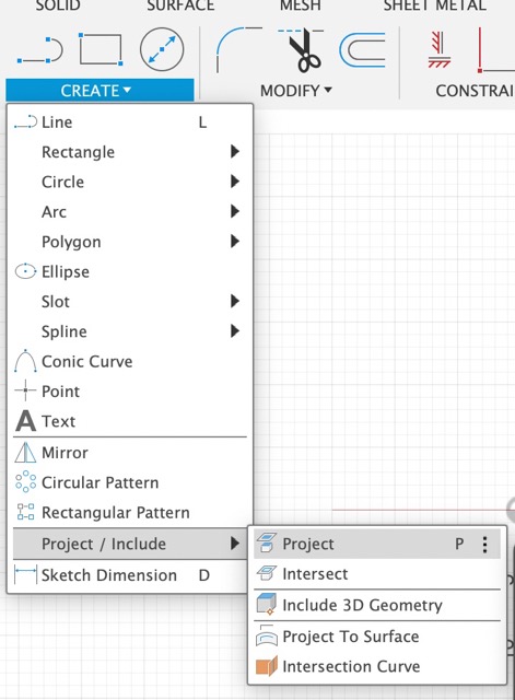
I used the align/move tool to fit the pieces together and to check if the dimensions were accurate. At this point, I realized I needed to incorporate dog-bones into my design, as the CNC machine could not cut a perfect 90º angle. I downloaded the dog-bone extension and moved the renamed file to Library> Application Support>Autodesk>Autodesk Fusion360>API> AddIns. Re-opening Fusion360, I went from Utilities> Add-ins>Scripts and add-ins and selected the add-ins tab. I clicked on the dogbone option, selected Run on Startup, and hit run. This creates a new dog-bone tool in the Solid Create menu of Fusion360. The tutorial for this process can be found here.
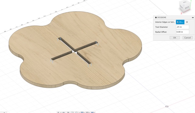
I applied the dog-bone to all of the slots in my design by clicking the interior edges.
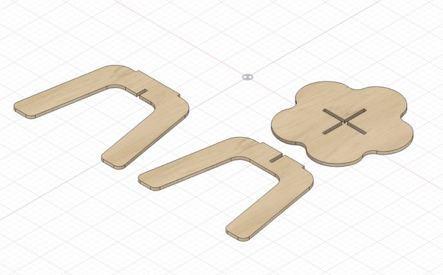
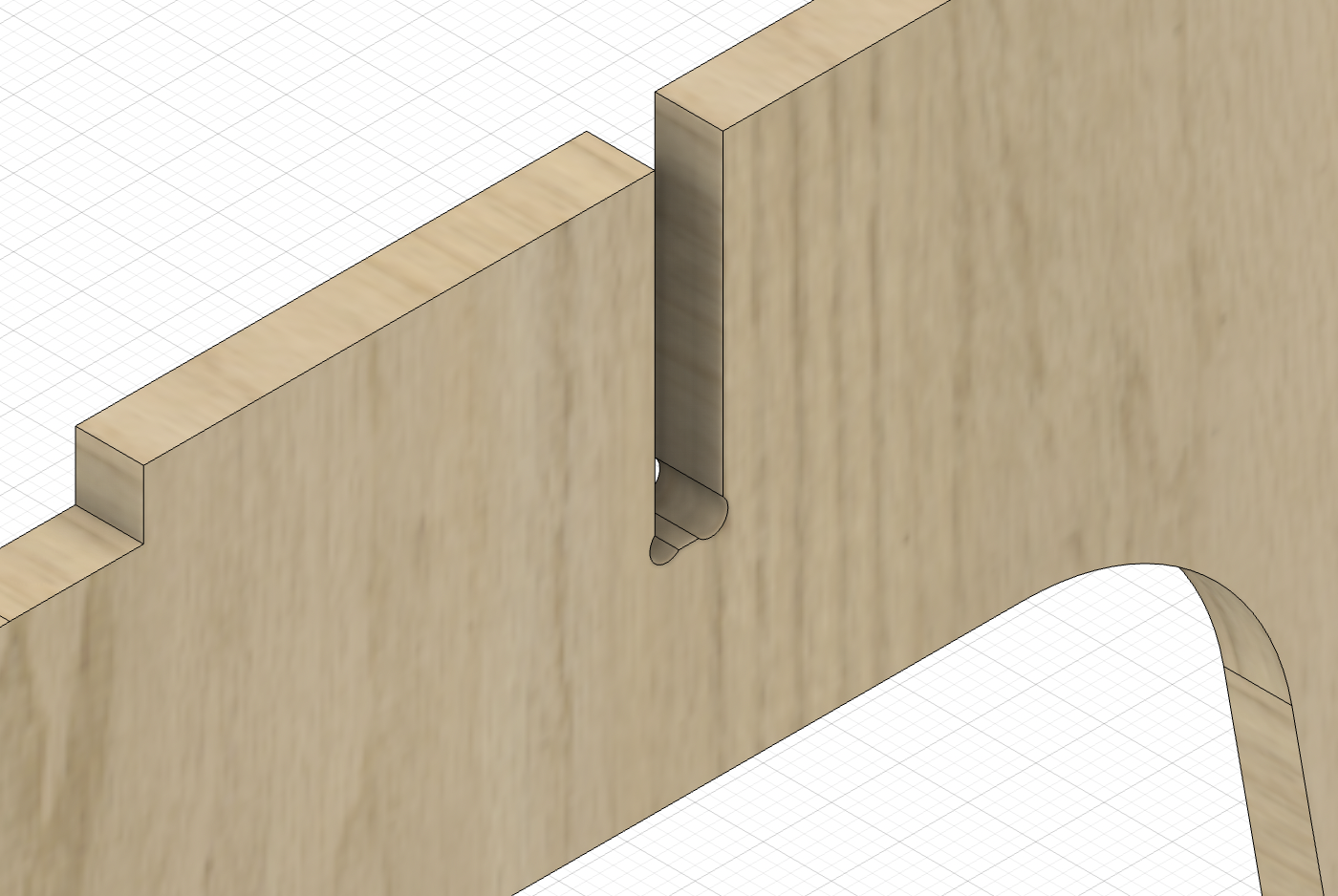
The dog-bone extension was super easy and intuitive to use! Here is what the leg looked like after applying dog-bones:
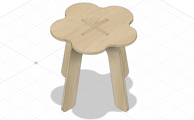
And here is my final assembled design:
I used the project feature to create a new sketch with the dog-bones included.
Around this time, I was also planning out my final project design, and I realized that the table was a bit more complex than I originally thought. Given the time constraints (my school was on spring break at the time), I decided to shift gears and focus on milling my final project floor table first.
Designing Final Project Table in Fusion360
For my table design, I took a bit of inspiration from Teddy Warner’s and decided to do a layered approach with my plywood. I struggled a bit with visualizing my new project idea, as I wanted there to be a top/bottom layer of wood, as well as a middle layer that could contain electronics and neopixels. After drafting several ideas, I settled with the simplest: a multi-layered table with epoxy resin built into the top layer.
I began sketching out these layers in Fusion 360.
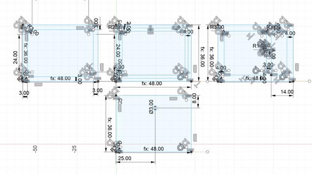
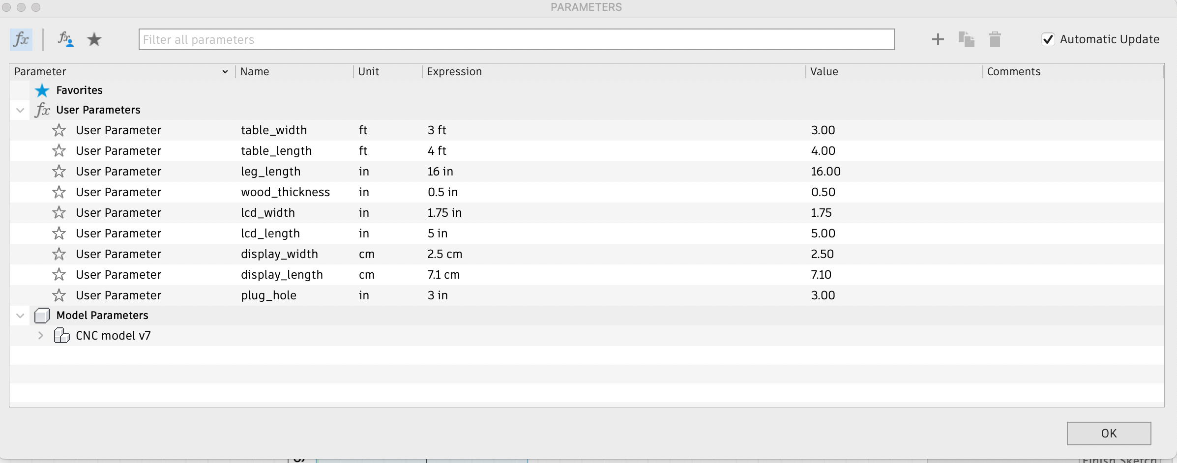
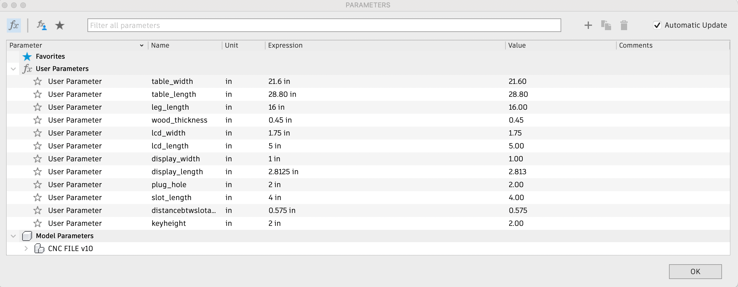
Here are the original parameters I established.
Note that these parameters were not accurate to the final product, as I had to scale the design down quite a bit. I ended up changing the design a lot, moving from a 3’ x 4’ table to a 28.8 ” x 21.6”.
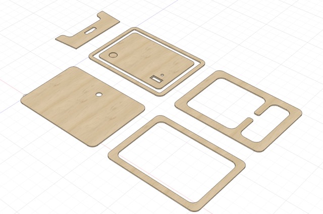
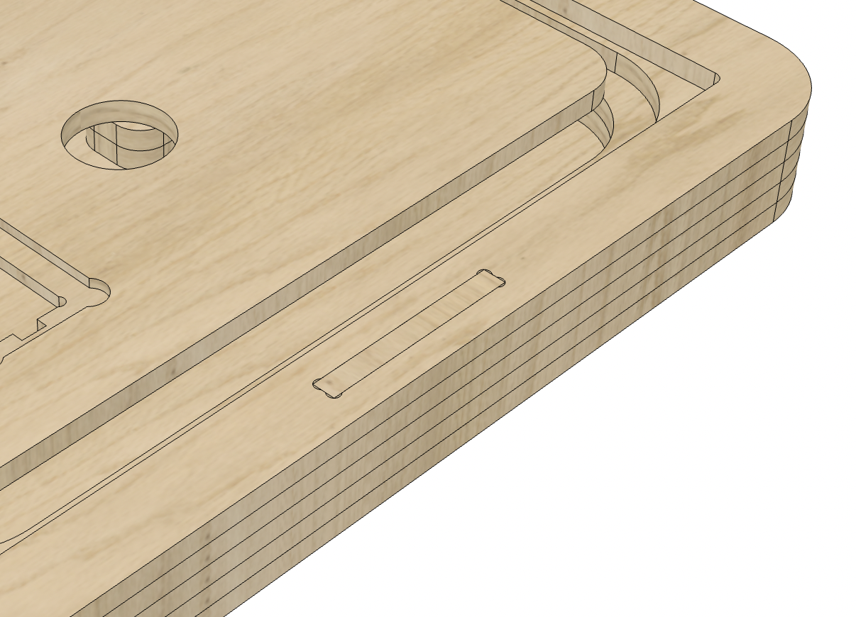
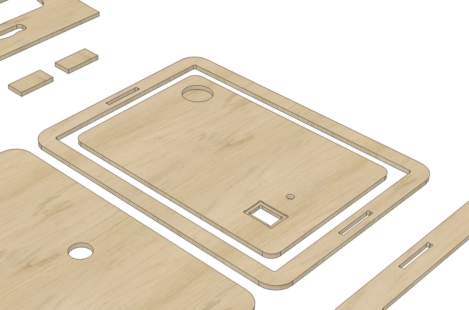
I extruded this by .5”, created a new sketch on the face of the top layer, and began adding additional features. At a minimum, I needed to add a section for the LCD screen (with dogbones on the corners) and a hole for wiring the ring neopixel.
This is what the design looked like:
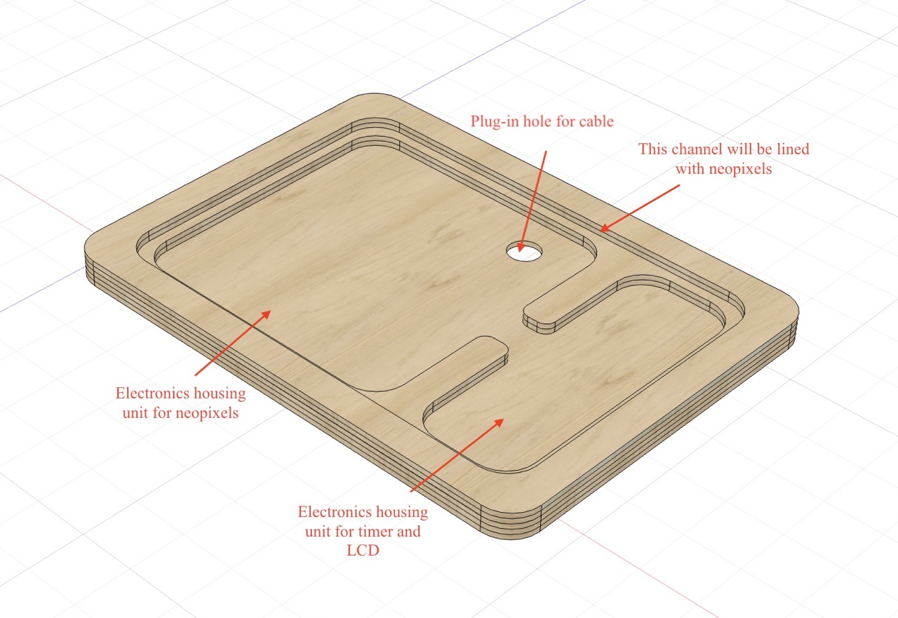
I also made an annotated version to better articulate what I wanted to do with each layer:
My initial plan for assembling was to use a strong adhesive, such as wood glue. However, after reconsidering the joints, I wanted to try using a simple tenon with star mortise, having a simple block serving as the “key” between the layers.
As I created this design, I was also entering outputs week, where I learned more about tft lcd touchscreens. In an effort to be more ambitious, I rearranged my design, moving the cup holder up the desk and adding a separate screen. I saved my sketch layer with the dogbones as a dxf and began creating a toolpath in Aspire!
Creating a Toolpath in Aspire (CAM)
To generate the toolpaths that the CNC machine would follow, I used Vetric CNC’s Aspire CAM software.
Opening Aspire, I was immediately overwhelmed by the software and the amount of tools it had. I wanted to first better grasp the interface and the purpose of each tool, so I watched this tutorial, which was found by classmate Landon Broadwell.
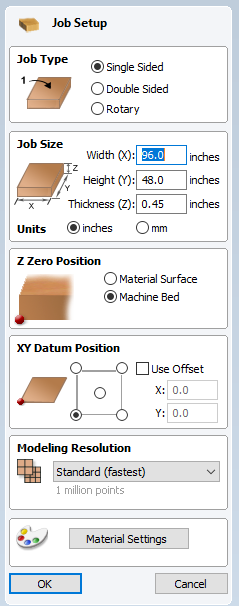
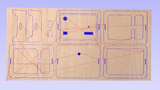
After watching this video, and thinking thorugh what types of cuts I wanted to do, I opened my dxf file in Aspire and configured the job setup settings. The sheet of plywood I was using, as mentioned earlier, is 48” x 96”, so I input those values, alongside setting the z zero position as off the machine bed. I kept the rest of the settings as standard.
Once I was in the main workspace, I selected all of the vectors and used the join vector command to ensure all of the design was properly enclosed. Now I could begin selecting parts of my file for profile and pockets.
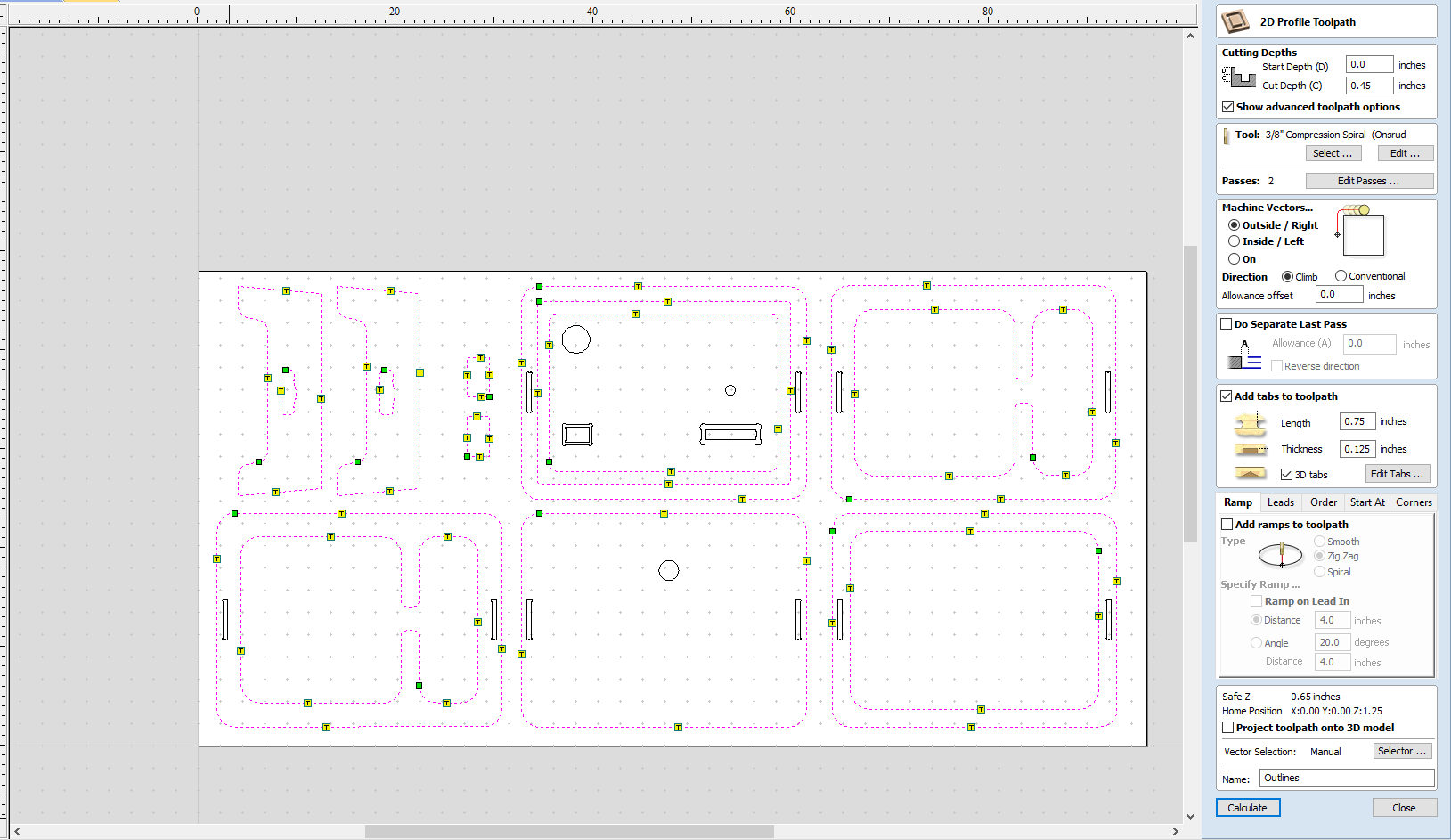
First, I set up a profile cut for the outline of my board by clicking the profile icon in the right-hand toolbar.
Here were my settings for profile:
-
I set cut depth to 0.45”, as I needed to fully cut through the material
-
I selected the tool as 3/8” compression spiral and edited the passes from 2 to 4
-
I moved the cut to the outside of the vector
-
I added tabs to the design, approximately 1 per side
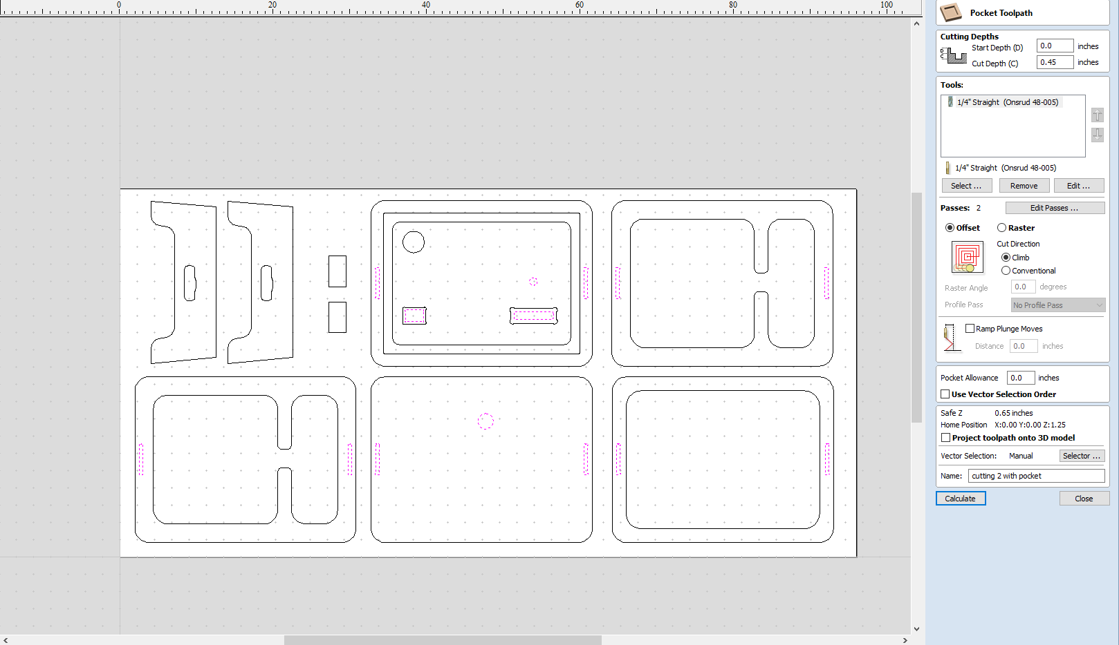
Second, I set up a pseudo-pocket cut for the smaller aspects of my table that still needed to be fully removed. My settings for this toolpath were virtually the same, except for the tool (I used the 1/4” straight because the slots were quite small) and the addition of tabs. Because it was a pocket, it automatically cut on the inside of the vector.
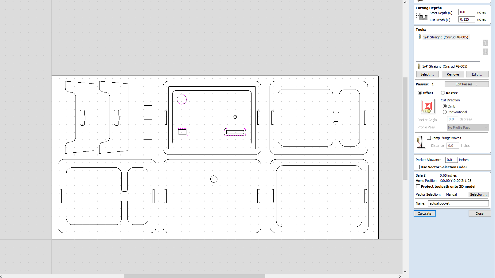
Third, I did an actual pocket for the LCD screens and the cup holder.
Here were my settings for the pocket:
-
I changed the cut depth to .125” deep
-
For tools, I used the 1/4” straight as these areas were also small and cannot be milled with the 3/8”
-
All other settings were kept standard
When I moved to the 3D tab, I could see these toolpaths simulated.
Setting up the CNC Machine
Workflow
When milling my table, I modified this workflow, originally designed by Mr. Dubick, with the updated procedure for aircuts:
1. Basic Setup and Safety Procedures
-
Put on eye and ear protection
-
Close the doors
-
Check to see that the machine has been warmed up; ensure that the start of day routine has been completed beforehand.
-
Measure thickness of material that you plan to cut.
-
Attach material to the table using nails
2. Start up Aspire software
-
Open your design file in Aspire
-
Select objects you wish to cut
-
Select appropriate toolpath
3. Click on material setup
-
Check Z - zero is on the bed, NOT the board
-
Enter the thickness of the material *
2a. Model position material should be the same thickness of the material.
-
Click OK.
4. Go to TOOL PATH OPERATIONS
-
Select 2D Profile Toolpath
1a. Under cutting depth, select the cut depth of the material (CLS tools). 1b.Select the proper tool 1c. Click add tabs and add tabs to the sides accordingly 1d. Hit CALCULATE.
-
Preview toolpath
-
Click on CLOSE
-
Select SAVE TOOL PATH and save the file in a shopbot format
5. Start ShopBot Command Console
6. Conduct Air cut
-
Select PART FILE-LOAD
-
Load the appropriate file
-
Once the material is secured to the spoilboard, bring the spindle to the origin (JH)
-
set Z-Height to 1 inch above the material
-
Use the zero-z-axis (Zz) command to zero the Z-axis for a new temporary origin above the material
-
Run the file with no offset
-
Once the routine is complete, run the C3 command to rehome the machine and resset the z-zero height to the machine bed
7. Perform Cut
-
Select FILE-LOAD
-
Load the appropriate file
-
Press enter to run the file
-
Turn on the spindle by pressing the GREEN Button
-
You should hear a “SOUND”
-
Turn on the vacuum
-
Press enter again to start cut
8. Post cut procedures
-
Turn off vacuum (which is so loud you shouldn’t forget)
-
Remove each piece from the tabs with a chisel and mallet or use a separate tool
9. Clean after yourself
Cutting the Components: Iteration 1
Fixturing
With the assistance of my instructor, Mr. Dubick, I first fastened my wood to the table by aligning the edge of the wood with the selected origin from earlier, inserting the air pressure nozzle onto the nail gun, and pressing the nails into the board. I did around 3-4 per side, around 1 inch from the outside. Additionally, referencing my Aspire file, I put in two nails in the in-between areas of the board where there would be no profiles/pockets. I marked these with a pencil beforehand.
Air Cut
I opened up my file in Aspire, saving it to the computer as a crv3d file. With the part file upload command, I uploaded the new file to the ShopBot software. To make sure that the CNC machine follows the toolpath accordingly, I ran an aircut by setting a 1-2 inch z offset above the material. One of the main things I learned during this process was the importance of being patient, attentive and understanding exactly what each indication and process meant.
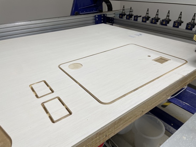
Profile and Pocket
I used C3 after the aircut to rehome the machine and reset the Z-zero height to the machine bed. Loading the file again and turning on the dust collector, I ran the job. There was only one issue during this time–the dust foot kept falling off when the ShopBot changed bits, so I paused the job and let Mr. Dubick rearrange it.
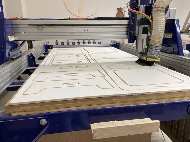
Profile cut in progress..
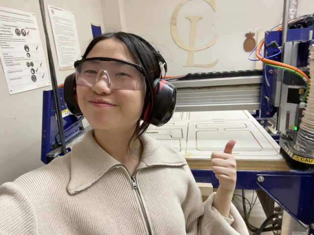
And an obligatory selfie for not blowing the CNC machine up!
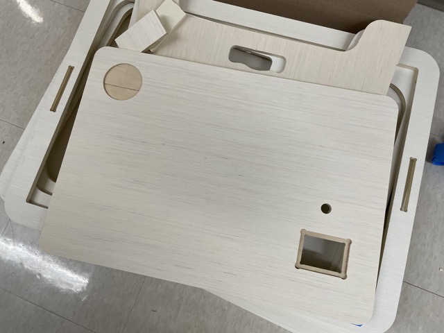
Removing the Tabs
Although there were no physical errors with the cut, I did find some dimension-related issues, especially with the LCD screen. It ended up cutting too long, despite the original dimensions I set up. Additionally, I noticed that the rectangular key was a bit too short. I assumed these were mostly careless design errors I had made, so in an effort to redesign, I tried to be as careful as possible in making sure my dimensions were accurate. In the future, I would also try to do a test cut with the laser cutter.
Prototype 1 pieces with failed top :,)
Re-evaluation and 5 Stages of Grief
I was honestly a little bummed that my design didn’t turn out as intended, but making these mistakes allowed me to re-evaluate how to better optimize this desk with interesting features, while maintaining enough room to actually work. As a stylistic preference, I kept the the cup holder at the top, and I decided to just keep one LCD in the bottom right corner.
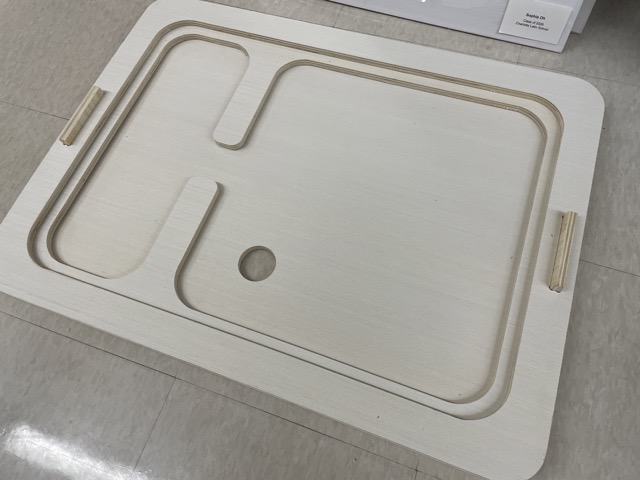
Here is the edited top layer.
Cutting the Components: Iteration 2
Thankfully, classmate Ryan Zhou was getting ready to use the CNC machine, and allowed me to cut my new top layer on the same file.
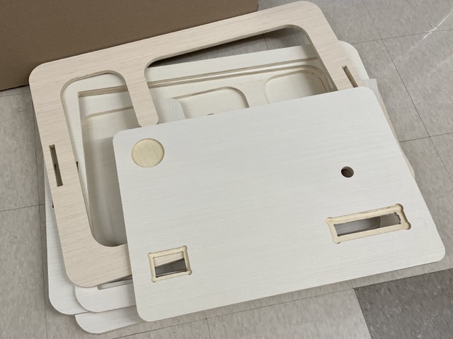
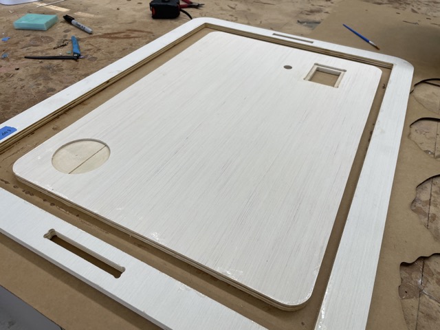
This variation turned out as intended, and the screen fit into the cut-out slot too!
Here is what all of my components look like altogether:
Resin
Updated as of June 5th:
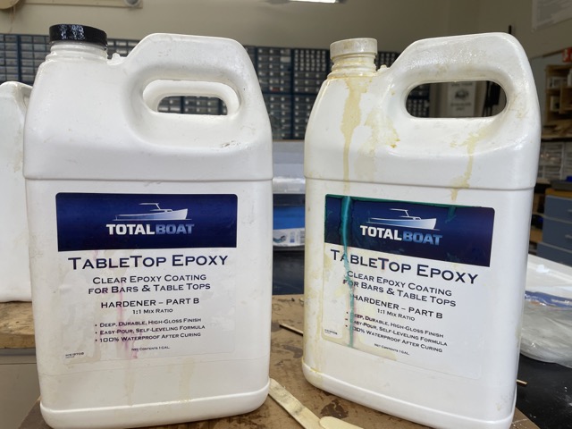
After discussing with Mrs. Morrow about what type of resin would work best for a .5” pour and approximately 1200 mL volume, she suggested the Totalboat Tabletop Epoxy (1A:1B). We were initially considering the Totalboat Thickset epoxy, but we concluded that it was too runny and inconvenient to use in a short time frame.
Sealing the Wood
The first thing I had to do was seal the edges of my wood that would come in contact with the resin. This ensures that the resin won’t sink and affect the wood. For this, I also used the Totalboat Tabletop Epoxy.
After mixing for 5-7 minutes, I simply painted this over the edge and left it to set for 24 hours.

When I went to check on it the next day, I noticed that parts of the cardboard were stuck to it, so I ran the orbital sander with 220 grit sandpaper over it a couple of times.
Pouring and Polishing the Resin
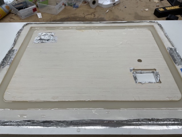
The lab had recently gotten aluminum foil tape, and I wanted to see how effectively it could protect the wood from the resin. I simply ripped off a large portion and wrapped the perimeter in it. I also covered the slots and the area for the screen in tape.

Note: to ensure that the distance between the center piece and the outer ring was consistent all the way around, I laser cut a cardboard spacer and used it as a reference.
Because the tabletop epoxy undergoes a exothermic reaction when it sets, I needed to do a 2-3 layer pour over a few days. I initially started out with 200g of part A and 200g of part B (first two layers), mixing in a small spoonful of pearl white pigment before moving to 60g of A to 60g of B to create the finish. After each pour, I used the heat gun to briefly remove the air bubbles within the resin.
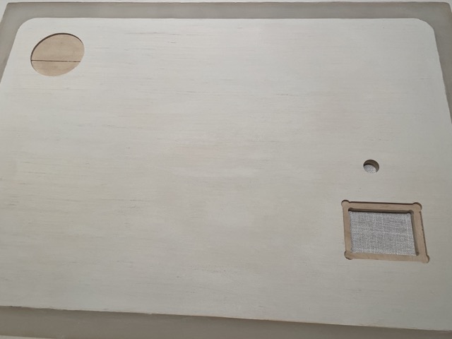
Once the resin was set, I again used the heat gun to remove parts of the foil that had stuck to the resin. Then, I used a mallet and a chisel to remove the entire piece off of the melamine board. Thankfully, the resin didn’t stick to the board, so I was able to get it off relatively easily. However, some of the resin did flow underneath the wood, causing it to be slightly uneven at some parts. To fix this, I simply ran the wood underneath the drum sander with the help of Mr. Budzichowski. Additionally, I applied a white primer (purchased from Sherwin-Williams), since sanding the wood resulted in its yellow undertones coming through. Here is what the top looked like after:
Assembling the Table
To assemble the table, I simply stacked the layers of wood on top of each other and inserted the key into the slot.
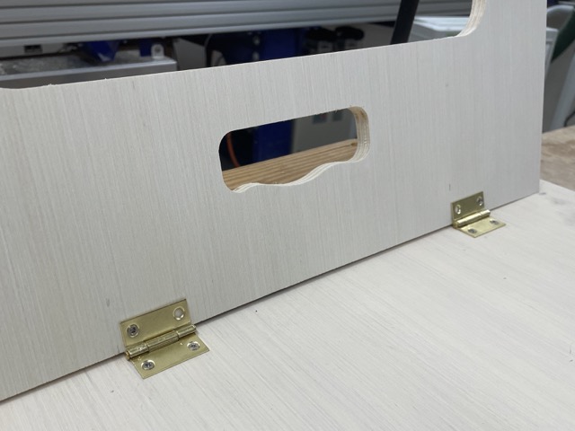
Additionally, I needed to install the hinges onto the bottom of my desk, which would allow the desk to be foldable and easily used on both the floor and on top of an existing table. With the help of Mr. Budzichowski, I first used the table saw to create an angled cut on the legs of my table, before using a power drill and small screws to install the hinges. I didn’t have much experience using a drill previously, so it was a bit hard to get started; however, with practice (and guidance from my peers), I gradually got better!
Here’s the base of the table standing:
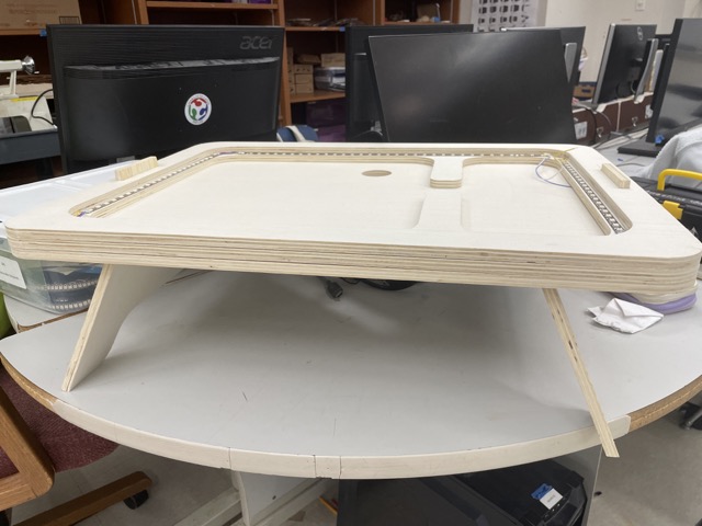
I had some initial doubts about whether the legs/hinges would actually be able to support the weight of the desk, but it seems to be holding up fine :)
The last thing to do was insert the top layer:
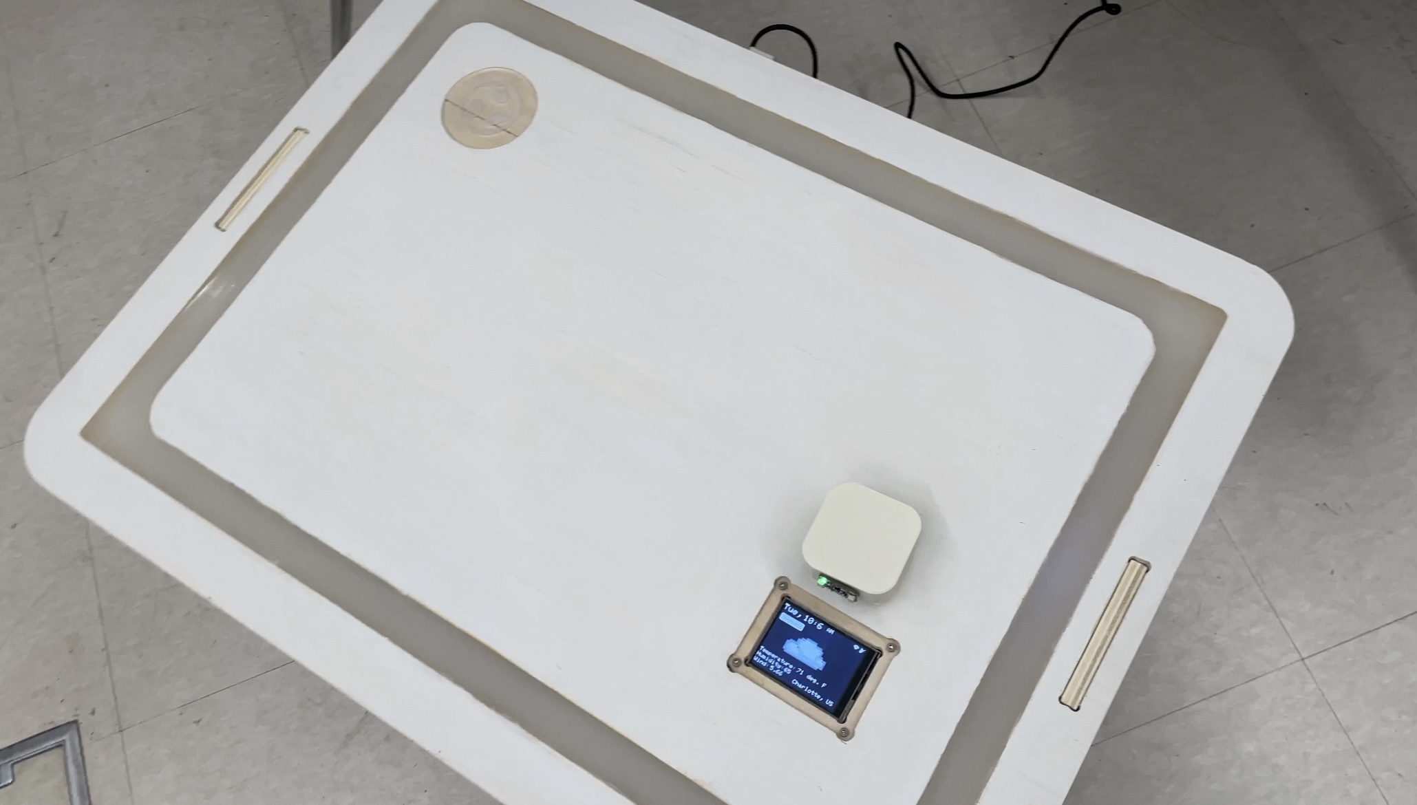
Top view of the finished desk
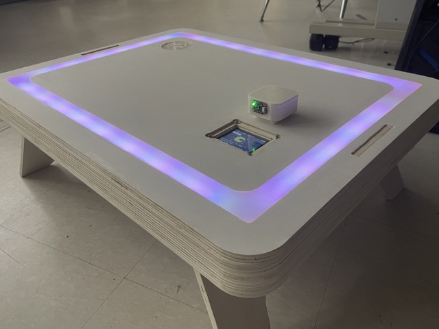
Lit up desk at night - updated post-final project
Group Assignment
For our group assignment, we learned about fixturing, runout, materials, alignment, toolpaths, etc. and how they affected the outcome of the cut. You can find our full documentation here.
Individual Contribution
For my individual contribution, I completed the runout test on the ShopBot and documented findings for the group page. Credits to the images belong to Group 7b.
Reflection
Did anything work out on the first try? No. Was I mourning for my first prototype? Absolutely. But despite these challenges, I was ultimately glad I could make these types of “big” mistakes, for they not only taught me how to better design CNC files, but also how to stray away from the perfectionist mindset that often dictates how I judge my work. I learned how to accept mistakes and treat them as a means to continuously iterate and improve.