14. Networking and communications
Throughout this week, I explored UART and more I2C connections, ultimately creating a xiao RP2040 to ATtiny1614 system. You can find all files here.
Assignment
group assignment:
- send a message between two projects
individual assignment:
- design, build, and connect wired or wireless node(s) with network or bus addresses and local input &/or output device(s)
I2C: Inter-Integrate Circuit
Resources:
Before starting I2C, I first explored these resources to figure out how the protocol worked. I learned that I2C consists of two main data lines, SDA(Serial data) and SCL (Serial clock). One board acts as the master, and the other as a receiver or a node with a unique address based on the number of bits.
Creating a Pomo-Master and Node Board
Designing in KiCad
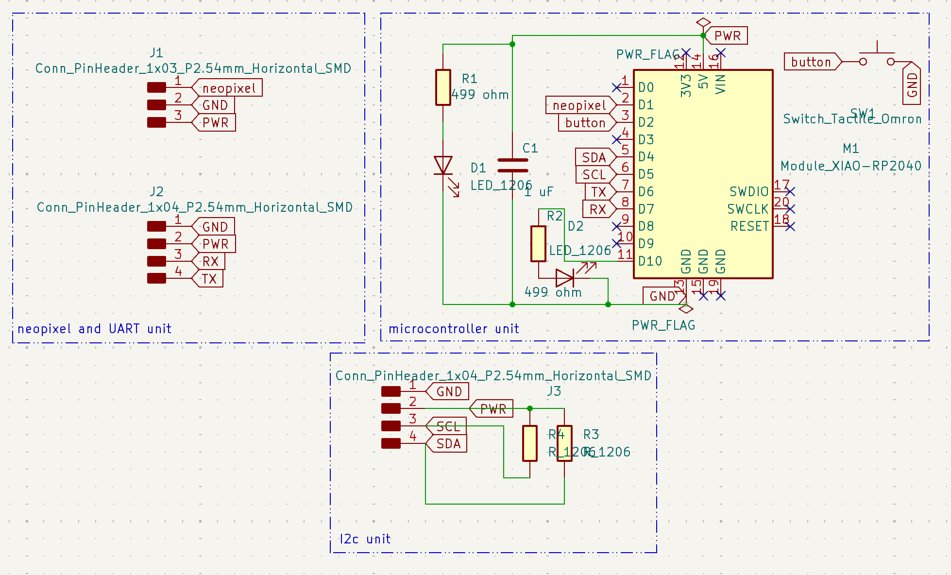
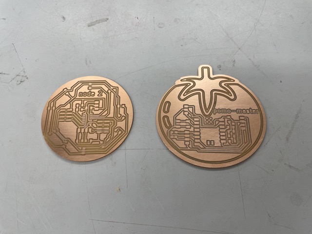
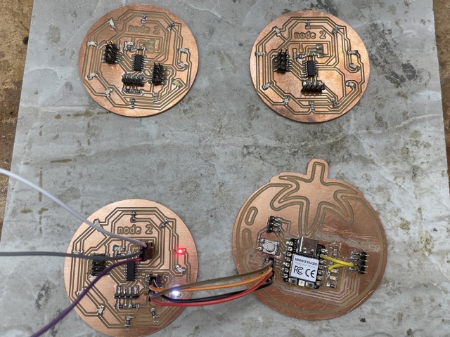
While designing my networking board for this assignment, I chose to create an all-in-one board, including SDA/SCL pins for an I2C connection, as well as RX/TX pins for UART (though for this week, I’ll be primarily using I2C). I wanted these boards to be used for my final project as well, so I tried to incoporate other useful aspects, such as separate I2C pins for a time-of-flight sensor, a button, and LEDS for charlieplexing (refer to Electronics Design). I ultimately created a master with the xiao RP2040 and a node with the ATtiny1614. After a few tries of routing these boards, here is what I came with:
Pomo-master Board:
For the edge cuts of my board, I wanted to do a design that related to my final project, similar to how Teddy Warner created aqua-ponics related boards. Thus, I searched online for a .svg of a tomato, since tomatos are often associated with the pomodoro technique. I scaled this file up in Fusion360, before returning to Kicad and selecting File>Import>Graphics. To create the outside shape as well as the interior details, I created two .dxf files and subsequently inserted them onto the edge cut and silkscreen layers.

Disclosure: this is a tomato, not a pomegranate.
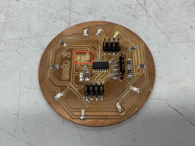
ATtiny1614 Board:
This was my experimental board, so I wanted to include RX/TX pins, I2C communication pins, I2C pins for sensors, charlieplexing, phototransistors, etc. Here is what the schematic looked like:
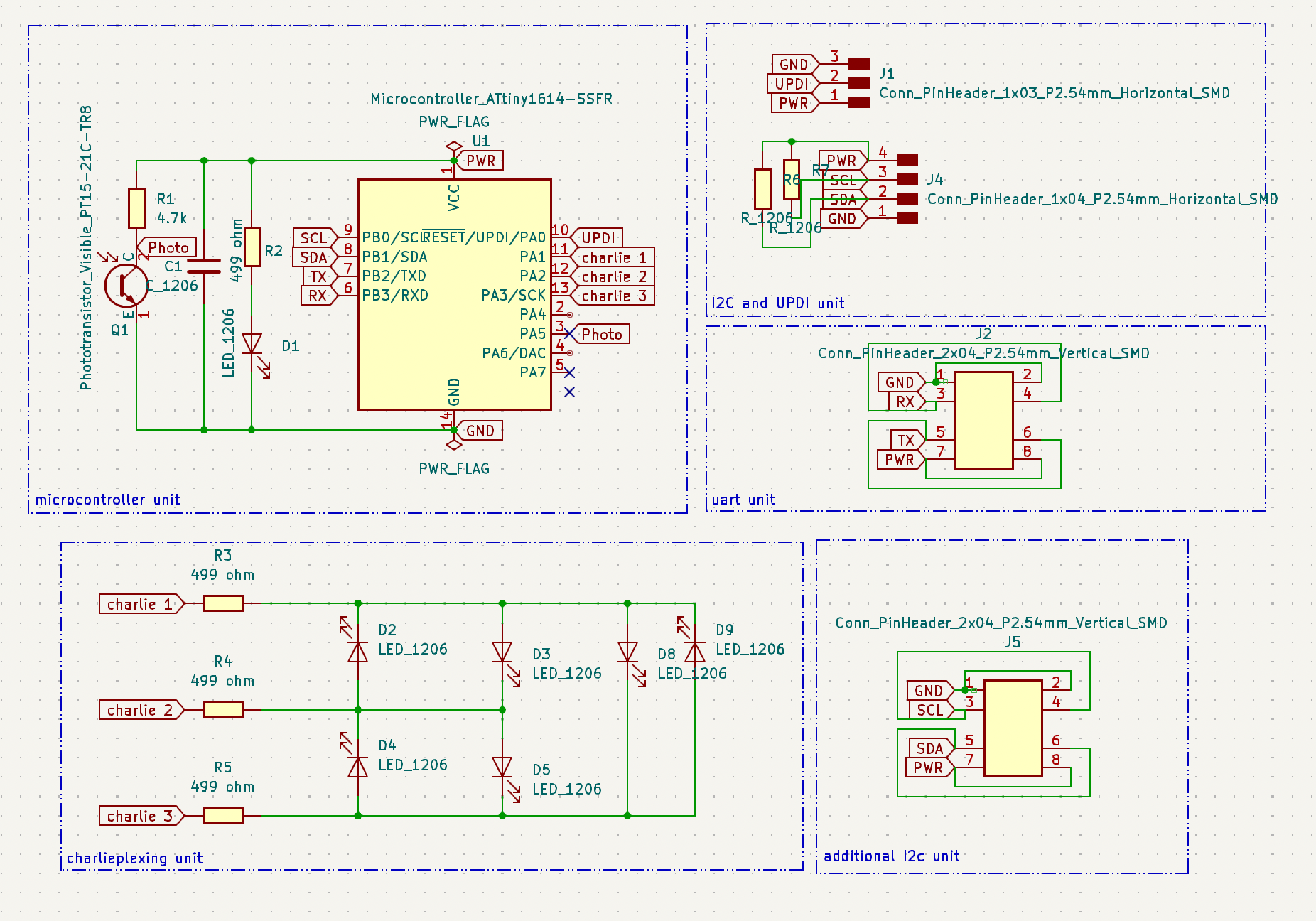
Although the ideas behind the board were fun in hindsight, routing it was truly hectic. I ended up using two different trace widths, between 0.5 mm and 0.3 mm, for many of the traces that ran below components.
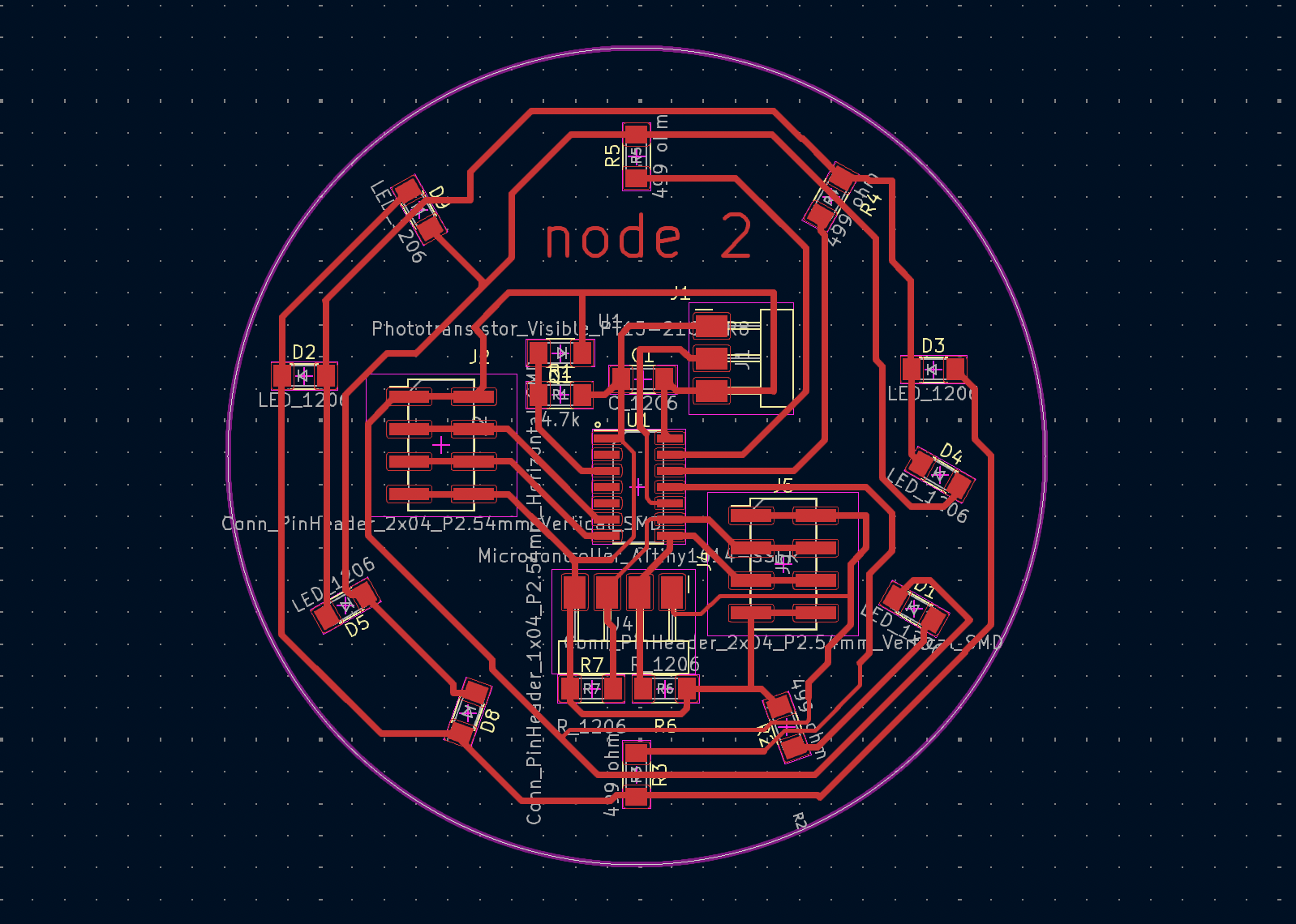
Milling and Iterations
In terms of milling, I followed the same process as previous weeks–plotting/saving my KiCad files as Gerbers, importing into the Bantam software, and configring z-axis and tool settings. The only difference this time was the tool I used for the tiny traces between the ATtiny pads, in which I selected the .005” engraving bit.
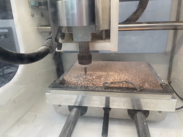
A few times during the outline, I noticed that the bit was plunging into the spoilboard and producing a loud noise. I fixed this later on by slightly increasing the z-material offset until the sound was reduced (though I did break a bit the first time this happened..).
Afterwards, I soldered on the following components:
Pomo-master Board:
| Component | Quantity |
|---|---|
| Seeed Xiao RP2040 | 1 |
| SMD red LED | 2 |
| 4-pin SMT vertical male header (FTDI) | 1 |
| 3-pin SMT vertical male header (FTDI) | 1 |
| 499 1206 SMD resistor | 2 |
| 970 nF capacitor (~1uF) | 1 |
| Milled PCB | 1 |
| Tactile push button | 1 |
ATtiny1614 Board:
| Component | Quantity |
|---|---|
| ATtiny1614 | 1 |
| SMD red LED | 2 |
| SMD green LED | 2 |
| SMD orange LED | 2 |
| SMD white LED | 1 |
| 4-pin SMT vertical male header (FTDI) | 1 |
| 3-pin SMT vertical male header (FTDI) | 1 |
| 499 1206 SMD resistor | 4 |
| 970 nF capacitor (~1uF) | 1 |
| Milled PCB | 1 |
| 2x04 SMT vertical male header | 2 |
| 4.99 k 1206 SMD resistor | 3 |
| SMD visible and IR phototransistor | 1 |
Programming The Boards Individually
Although soldering and milling had brought few setbacks, the programming portion was quite difficult–even when programming the boards individually. Not only did I receive the UPDI initialization failed each time I uploaded a program through the QuenTorres board, but I had also gained a new error, RSP_NO_TARGET_POWER. At the same time, I managed to rip the copper pads off my two iterations I had created at that time, meaning I would have to start over from scratch :(.
RIP to my record of not ripping traces..
While I was producing the third iteration, Teddy Warner visited Charlotte Latin and talked a bit about his pitch and new company. I eventually let him choose (bless) the ATtiny1614 on my new board. This board turned out way better than previous versions, and it was able to properly receive code through JTAG. However, I was struggling to get my charlieplexing to fully work. For some reason, only 2 out of the 6 LEDs were turning on! After an hour of troubleshooting, I realized that the soldering between the charlieplexing 1 pin and the resistor wasn’t solid, so I went back in and fixed the connection.
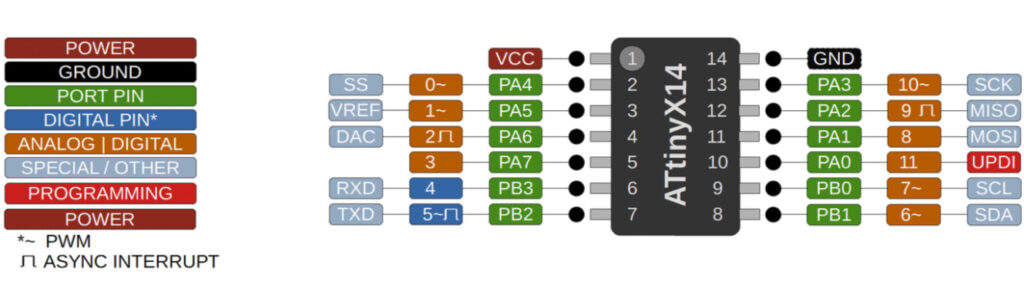
For reference, I used the same code as I did in Electronics Design week, only changing the charlieplexing pins to 10, 9, and 8 based on the ATtiny1614 pinout.
Here is the charlieplexing working:
Thank you to Teddy Warner for choosing the ATtiny :>
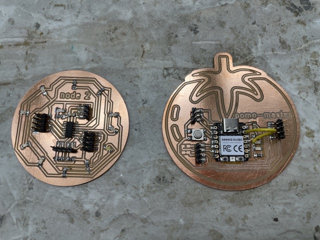
Below are the final boards side-by-side:
After milling the ATtiny board three times total, here are all the iterations laid out:
Programming and Troubleshooting
After looking at Adrian Torres’ documentation, I was able to understand how basic programming for I2C worked. For instance, wire.begin() or wire.begintransmission() initializes the I2c bus for each board. Then, using wire.write(), the user can write data from one device to another. The board that receives data implements the onReceive() function to accept the transmission, before using wire.end() to close the I2c bus. For more information regarding these functions, reference this website.
I connected GND to GND, SDA to SDA, and SCL to SCL before uploading [Adrian Torres’] code. I changed it so it could blink one of the charlieplexing LEDs, though nothing happened when I uploaded. Thus, I went back through to reinforce my soldering and check for potential bridges. I had used solder paste, and I notice that it spreads quite easily. After fixing this (and checking continuity), checking, and testing, I found no changes in my results. At this point, I wondered if the errors had to do with my software. I cross-compared my code with several others that had done I2C in the past, and I couldn’t find anything wrong about it!
It was getting a bit frustrating at this point, so I turned my struggles over to Mattermost and spoke to Adrian Torres for help. He suggested that I use a logic analyzer to probe the SDA and SCL signals. I found that the signals for each were constantly high, indicating that 1) there was simply no transmission between the two, and 2) the pull up resistors seemed to be working. Then, suggested by Leo Kuiper, I set my SDA and SCL pins individually to HIGH/LOW and similarly probed it with the logic analyzer. Here, I found something strange: the RP2040 was changing from HIGH to LOW correctly, but the Attiny wasn’t.
Confused, I decided now to test each one with a regular Arduino Uno. Here was my setup:
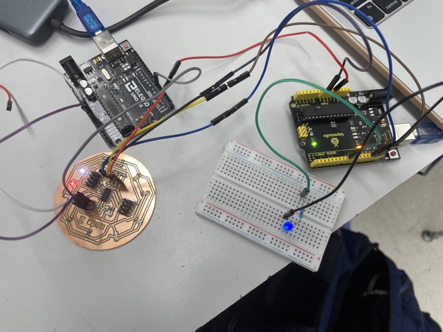
I simply hooked up the I2C pins and connected pin 8 on the Arduino to a resistor and LED. I uploaded the following code:
Master Code:
#include <Wire.h>

#define SLAVE_ADDRESS 8
#define C1 10
#define C2 9
#define C3 8

void setup() {
  Wire.begin(); // join i2c bus (address optional for master)
  Serial.begin(9600);
  pinMode(3, OUTPUT);
  pinMode(C1, OUTPUT);
  pinMode(C2, OUTPUT);
  pinMode(C3, INPUT);
}

void loop() {
  Wire.beginTransmission(SLAVE_ADDRESS); // transmit to device #8
  Wire.write(1);
  digitalWrite(C1, HIGH);
  digitalWrite(C2, LOW);
  delay(1000);
  Wire.endTransmission();  // stop transmitting


  Wire.beginTransmission(SLAVE_ADDRESS);
  Wire.write(2);

  delay(1000);
  Wire.endTransmission();


  //delay(1000);

}
Node Code (Arduino):
int d1=0;
int LED=8;


#include <Wire.h>

void setup() {
  Wire.begin(8); // join i2c bus (address optional for master)
  Serial.begin(9600);  // start serial for output
  pinMode(LED, OUTPUT);
  Wire.onReceive(recieveEvent);

}

void loop() {

  if (d1==1) {
    Serial.println("received");
    Serial.println(d1);
    digitalWrite(LED, HIGH);
    delay(500);
    digitalWrite(LED, LOW);
    delay(500);
  }
  else if (d1 == 2) {
    Serial.println(d1);
    digitalWrite(LED, HIGH);
    delay(1000);
    digitalWrite(LED, LOW);
    delay(1000);
  }

  else {
    digitalWrite(LED, LOW);
    Serial.println(":(");
    delay(1000);

  }

}

void recieveEvent(int howMany)
{
  while (Wire.available())
  {
    d1 = Wire.read();
  }
}
I printed out values of d1 on the serial monitor to ensure that it was actually reading values from the master board, and to my surprise, it worked!
However, new issues arose when I then tested it by sending several messages (setting d1 to 1, and then setting d1 to 2). When viewing the serial monitor after making these changes, I noticed that the values for d1 were getting more erratic (not following a particular pattern). I played around with adding delay(1000) with the help of Mr. Dubick, but I kept getting the same results. Another issue was that the LED and ‘readings’ continued even when SDA and SCL were not actively connected between the two boards. I assumed that the Arduino was simply repeating the last pattern it had read from the attiny, but I’m not sure.
I took a break from I2C and decided to tackle it the next week, testing the tomato rp2040 and the 1614 board again. During this time, I also spoke to Dr. Harris, who explained that the attiny may have issues acting as the slave. I noticed that the attiny worked as the master when I tried it with the Arduino, so I used it as the master this time. I uploaded the following code:
Master Code (now Attiny1614):
#include <Wire.h>

#define SLAVE_ADDRESS 8
#define C1 10
#define C2 9
#define C3 8


void setup() {
  Wire.begin(); // join i2c bus (address optional for master)
  Serial.begin(115200);
  pinMode(3, OUTPUT);
  pinMode(C1, OUTPUT);
  pinMode(C2, OUTPUT);
  pinMode(C3, INPUT);
  Wire.begin(TOF);

  Wire.setClock(400000); // use 400 kHz I2C

  sensor.setTimeout(500);

  // Start continuous readings at a rate of one measurement every 50 ms (the
  // inter-measurement period). This period should be at least as long as the
  // timing budget.


}

void loop() {

  Wire.beginTransmission(SLAVE_ADDRESS); // transmit to device #8
  //Wire.write(1);
  digitalWrite(C1, HIGH);
  digitalWrite(C2, LOW);


  Wire.endTransmission();  // stop transmitting


  //delay(1000);

}
Slave Code (now RP2040):
int d1=0;
int LED=3;


#include <Wire.h>

void setup() {
  Wire.begin(8); // join i2c bus (address optional for master)
  Serial.begin(115200);  // start serial for output
  pinMode(LED, OUTPUT);
  Wire.onReceive(recieveEvent);

}

void loop() {

  //delay(50);
  if (d1==1) {
    Serial.println("received");
    Serial.println(d1);
    digitalWrite(LED, HIGH);
    delay(500);
    digitalWrite(LED, LOW);
    delay(500);
  }

}


void recieveEvent(int howMany)
{

  while (Wire.available())
  {
    d1 = Wire.read();

  }
}
After many tries, I was able to finally get it to work :,D.
UART: The Universal Asynchronous Receiver/Transmitter
UART defines a set of rules for exchanging serial data between two or more devices, or in this case, microcontrollers. Using only three signals, Tx (transmitted serial data), Rx (received serial data), and ground, it provides a robust way for users to access several microcontrollers at once and improves the processing speed overall.
I had originally intended to use UART in my final project to communicate between an xiao RP2040 and an attiny1614, but after repeated issues with UPDI initialization and lack of understanding of how UART worked, I decided to go back to a fundamental level and attempt UART on a breadboard with two Xiao RP2040s. For some guidance, I looked towards previous grad’s documentation. I ended up finding Ryan Kim’s documentation, who similarly experimented with xiao RP2040s and raspberry pi picos. After reading his documentation, I felt like I better grasped the basics of the protocol, including defining
In order to use the protocol, I needed to first create the following connections between the RX, TX, and GND pins:
         Sender                          Receiver

 +---------------------+          +---------------------+
 |        XIAO RP      |          | XIAO RP2040         |
 |         2040        |          |                     |
 |                  TX +----------+ RX                  |
 |                     |          |                     |
 |                  RX +----------+ TX                  |
 |                     |          |                     |
 |                  GND +----------+ GND                |
 |                     |          |                     |
 +---------------------+          +---------------------+

                     UART Prototcol
Below is my setup with the two xiao RP2040s. I included a resistor and an LED as well to serve as an active indicator of whether the serials were truly communicating with each other:
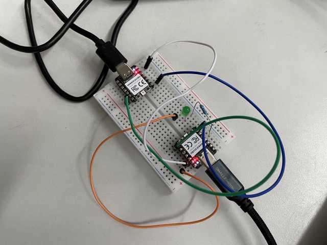
I plugged each xiao rp2040 into different computers, before selectingRaspberry pi as my board in Arduino IDE and uploading the following programs (modified). Note that these two programs follow a similar format, and there isn’t necessarily a distinct sender/receiver, as the boards are communicating mutually with each other.
Board 1 Code:
void setup() {
  delay(2000);
  Serial.begin(9600); // initializes Serial
  pinMode(29, OUTPUT); //defines pin for LED

  delay(200);
  Serial1.begin(9600, SERIAL_8N1);  //SERIAL_8N1 is the default available serial port; Serial1.begin() addresses 1 out of 2 devices involved in the protocol
  Serial.println("\n--- UART communication with XIAO RP2040 ---");
  Serial.println("SERIAL1_TX: " + String(SERIAL1_TX));
  Serial.println("SERIAL1_RX: " + String(SERIAL1_RX));
  Serial.println("-------------------------------------------------------");
}

void loop() {
  if (Serial.available()) {      // If anything comes in Serial (USB),
    Serial1.write(Serial.read());
    digitalWrite(29, HIGH);
    delay(500);
    digitalWrite(29, LOW);   // read it and light up the LED accordingly
  }

  if (Serial1.available()) {     // If anything comes in Serial1 (pins 0 & 1)
    char serial1_In = Serial1.read();
    Serial.write(Serial1.read());
    digitalWrite(29, HIGH);
    delay(500);
    digitalWrite(29, LOW);
  }
}
Board 2 Code:
void setup() {
  pinMode(29, OUTPUT);
  delay(2000);
  Serial.begin(9600);
  delay(200);
  Serial1.begin(9600, SERIAL_8N1);  //defines a unique Serial and addresses 1 out of 2 devices involved in the protocol
  Serial.println("\n--- UART communication with XIAO RP2040 ---");
  Serial.println("SERIAL1_TX: " + String(SERIAL1_TX));
  Serial.println("SERIAL1_RX: " + String(SERIAL1_RX));
  Serial.println("-------------------------------------------------------");
}

void loop() {
  if (Serial.available()) {      // If anything comes in Serial (USB),
    Serial1.write(Serial.read());
       // read it and send it out Serial1 (pins 0 & 1)
    digitalWrite(29, HIGH);
    delay(500);
    digitalWrite(29, LOW);
  }

  if (Serial1.available()) {     // If anything comes in Serial1 (pins 0 & 1)
    Serial.write(Serial1.read());
    digitalWrite(29, HIGH);
    delay(500);
    digitalWrite(29, LOW);   // flashes LED to indicate received message
  }
}
For more information regarding serial ports, visit this website.
Opening the serial monitors on both computers, I could send and receive messages now from both devices! At the same time, the LEDs turn on as an indicator. Here is what it looks like working:
Communicating Between Two Boards
Next, I wanted to try to communicate similarly between two xiaos with a custom milled PCB. To do this, I simply milled and soldered another copy of the tomato board and connected Rx to Tx, Tx to Rx, and GND to GND. I then uploaded the same code with a LED pin 3. At first, there were some issues with the serial monitor printing unknown symbols, but eventually, I got it to work and blink the LED.
Although this system worked pretty well and is deemed the “easiest form of networking,” I didn’t find the process very intuitive, and I struggled quite a bit to understand it conceptually. Additionally, this protocol simply isn’t as effective as others, such as I2C, when incorporating more than one node at a time.
Group Assignment
This week, we were tasked to send a message between two projects. You can find our full documentation here. David used his raspberry pi pico board to send 1’s and 0’s to my tomato RP2040 board.
Reflection
I think this was one of the hardest and most frustrating weeks for me, mainly because there was no “one way” to guarantee success. Certain iterations felt pointless, and I had no way of really checking if what I was doing was fully correct. Nonetheless, I made it through with the help of Adrian Torres, Mr. Durrett, and an unhealthy amount of luck (and perhaps others too for emotional support). This week also put into perspective the applications of networking and allowed me to re-evaluate how I wanted to approach the electronics in my final project.