6. 3D Scanning and printing
This week I designed a model in Fusion360 that could not be created using a subtractive process and 3D printed it. Addiionally, I explored various methods to scanning and modeling a design. You can access all of my files here.
Assignment
group assignment:
- test the design rules for your 3D printer(s)
individual assignment:
-
design and 3D print an object (small, few cm3, limited by printer time) that could not be made subtractively
-
3D scan an object (and optionally print it)
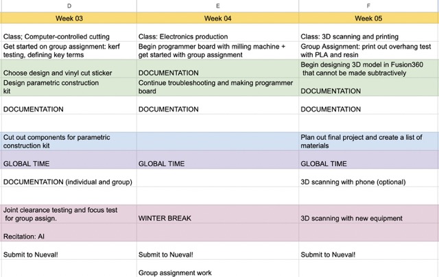
Here is my weekly schedule:
Additive vs. Subtractive
| Additive | Subtractive |
|---|---|
| Refers to a design that requires successive layers of material to create an object |
Removes material to create an object |
| Traditionally refers to 3D printing | Traditionally refers to CNC machining |
Designing and 3D Printing an Object
Making a Dodecahedron
For my 3D printed object, I chose to make a dodecahedron with a sphere on the inside, as that cannot be made subtractively. I took inspiration from Adrian Torres’ design, and I followed this tutorial to create the basic shape (mainly because I’m not very familar with the ‘surface’ tab of Fusion360). This design cannot be made subtractively as it would require, at least, a tool that can be used on several axes. Additionally, it will contain an object on the inside.
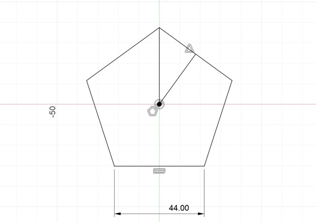
I started out by sketching a pentagon with the circumscribed polygon tool on the XZ axis, setting the side length to 44 mm.
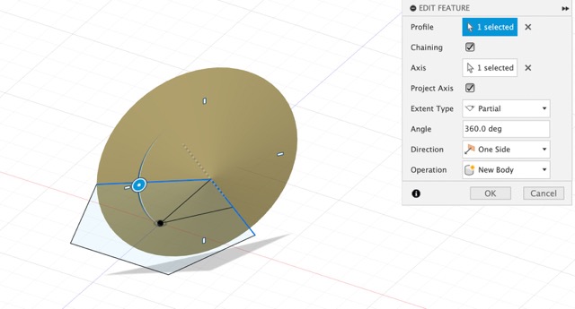
Next, under the Surface tab of Fusion360, I applied the revolve command twice, selecting one edge for the profile and the adjacent edge for the axis.
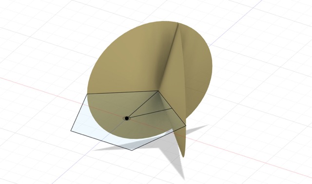
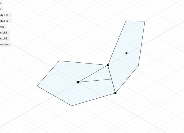
Here is the sketch after applying the two revolves.
Afterward, I applied the surface trim feature under the Modify drop-down menu and selected the revolved features. I then created a plane from 3 points and selected the top of the resulting body (1), the contacting vertex of the pentagon (2), and the adjacent vertex (3). This would allow me to create a new sketch at an angle.
In the newly created plane, I sketched an arbitrary pentagon and used the coincident feature to align the sides.
This is what the two faces look like!
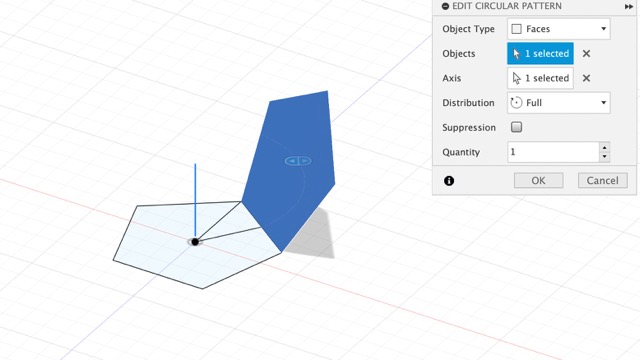
Now, I had to apply the circular pattern feature to the offset pentagon. To do this, I selected the newly created surface as the object and the upward axis as the axis (y in my case). I applied a surface stitch to merge the different faces.
I created one more offset plane that was parallel to the XZ plane. Selecting the entire design, I mirrored it about the plane and used the move tool to rotate it 36º, as instructed. This creates the fully closed dodecahedron.
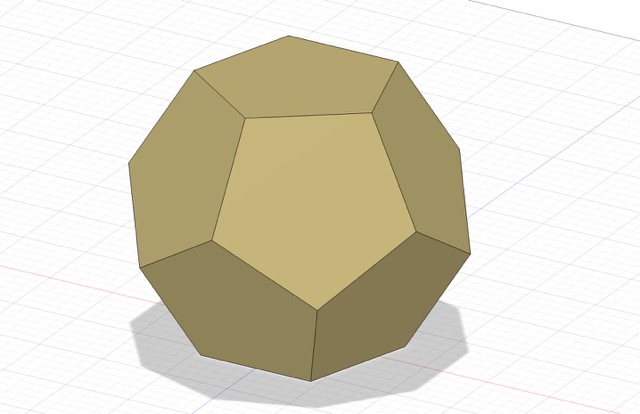
Although the general shape was created, the interior was still completely hollow. To fix this, I used the thicken command and made each wall 5 mm.
The next part of my design was to create offset pentagons on each of the sides and cut them out. I simply used the offset tool, sketched a 22 mm pentagon starting at the center of the face, and extruded it inwards.
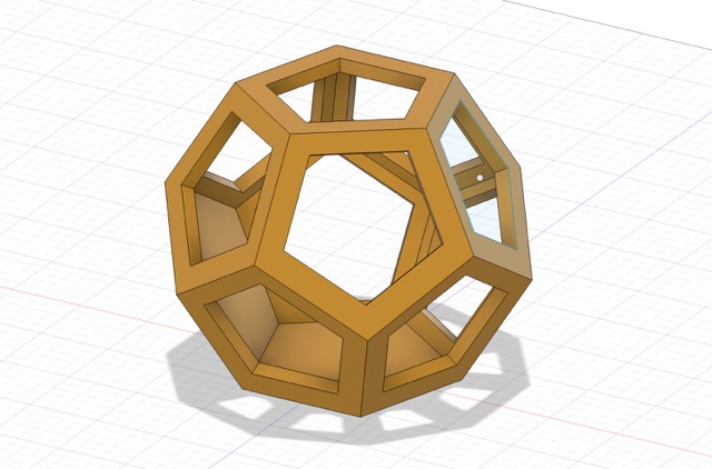
To create the sphere on the inside of my empty dodecahdron, I created a new sketch and used the sphere command, making it around 75mm. I wanted this sphere to move freely in the interior, so I also added five 2mm circular supports, which I extruded.
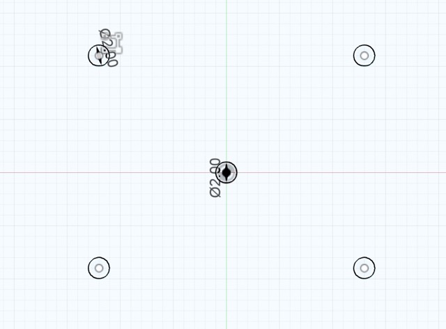
Here are the five circular supports! Mr. Durrett advised adding a support in the center to ensure that the sphere could be created without the help of additional supports when slicing.
Generating a G-Code
After creating the design, I exported it as a .STL file and moved it into PrusaSlicer, a program that allows you to generate a g-code from your 3D design. Upon importing, I selected 0.20 mm quality for the print settings, PLA for the filament, 15% for infill, and ensured that there were no external supports. I sliced the design and uploaded the g-code onto a Octoprint website that was connected to one of the 3D printers.
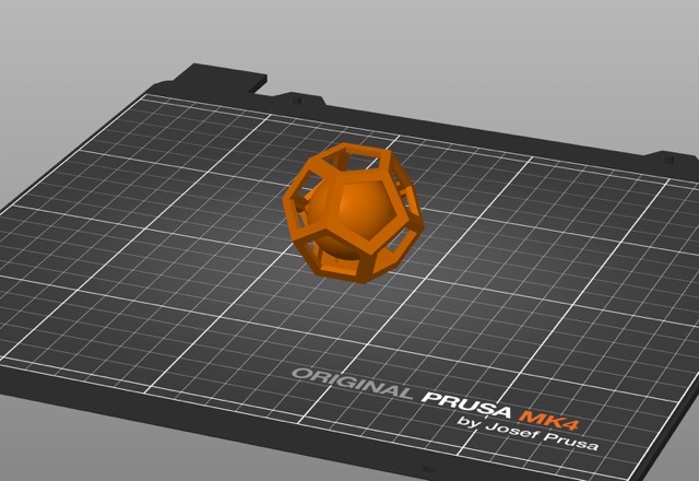
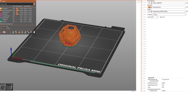
Here is the design in PrusaSlicer!
All that’s left is to watch the 3D printer make it :)
Once the print was finished, I cleaned and trimmed off some of the debris on top with a pair of scissors, before carefully breaking off the supports.
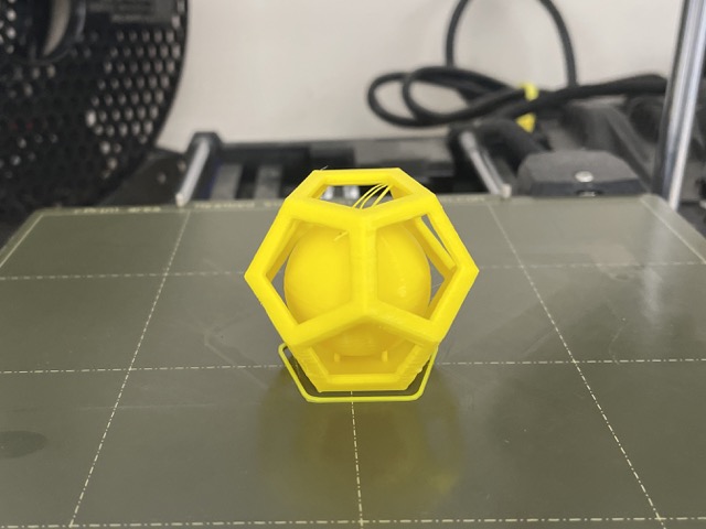
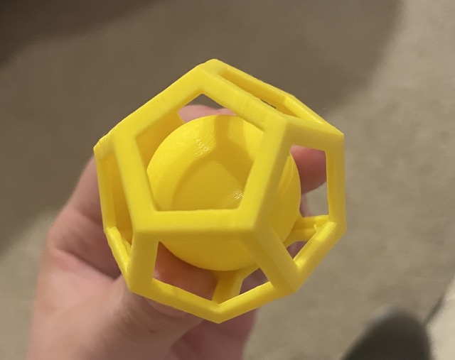

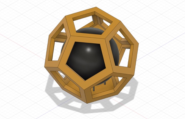
Here is the finished dodecahedron on the printer and from different sides.
I additionally made this cut-out dice by creating a cube with text on each face, and extruding each side respectively; I believe it can be made subtractively, but it was fun nonetheless.
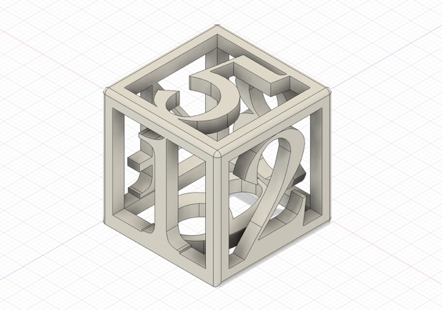
Here is the finished dice.
3D Scanning
For the scanning portion of this week’s assignment, I tested out two different applications: a free software called Qlone and a hand-held device made by Creality Scan Ferret Pro 3D Scanner.
Qlone
I first tested out Qlone, a more affordable and accessible scanner.
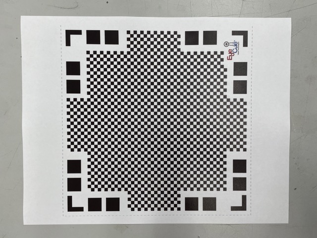
Upon downloading the app and printing out the required mat (required for non-premium users), I selected an object to scan. I chose to scan my friend’s scrunchy, so I placed it on the center of the mat.
Upon pressing the record button, I rotated the mat 360º in several iterations while keeping the camera still.
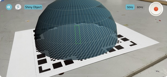
This is what the scanning process looks like, with the addition of an object on the mat.
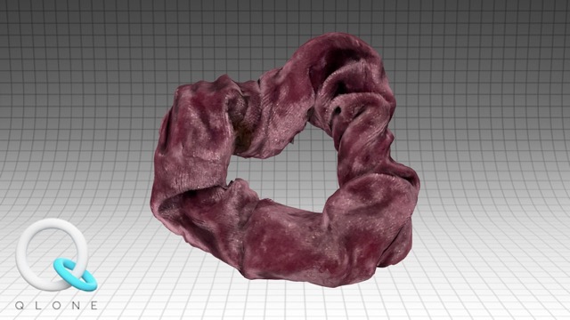
This produced a pretty accurate body, keeping the same texture, shape, and color. The only drawback was the bottom of the scrunchie, which wasn’t depicted in the scan.
Overall, I liked the convenience and speed of Qlone, though a lot of its capabilities (exporting, file types, etc.) are limited by the free version. I found that it performed surprisingly well with textured or irregularly-shaped objects, such as the scrunchie. In the future, I would like to try out more softwares in the future, such as PolyCam!
Creality Scan Ferret Pro 3D Scanner
Next, I tried out the creality scan ferret pro 3d scanner. This device acted as an extension of an app, so all I had to do was plug in the cord into the bottom of my phone. The app recommended that I scan human faces, human bodies, carving, etc.

When I plugged my device in, the app indicated that there wasn’t a connection between the scanner and the phone.
Group Assignment
For this week’s group assignment, we were tasked with testing the design rules for our 3D printer. This involved printing various torture tests, overhang tests, etc. and characterizing different parameters of the process. You can find the full documentation here.
Individual Contribution
I printed out the comprehensive torture test with Prusament PLA and the overhang test on the FormLab printer (resin). Additionally, I defined terms that Neil addressed during his class this week (i.e. infill, bridging, overhang, etc.). I documented these portions respectively.
Reflection
Because I already had previous experience in 3D printing, this week felt pretty streamlined and easy-paced. I enjoyed exploring the possibilities of an additive design, as well as printing the various torture tests in the group assignment. I feel like I’ve gained a better understanding of the Prusa Mini’s and Formlab’s limitations in terms of overhang. The scanning portion was also interesting, though free applications have their share of flaws. I remember Neil mentioning that this week was one of the most creative weeks, and I completely agree! I look forward to applying this week’s knowledge to my final project!!