3. Computer Aided design
This week, I explored various types of 2D raster/vector applications, as well as 3D CADing tools to model my final project You can access all files here.
Note to everyone reading this: I don’t recommend cadding with a trackpad :(
Assignment
- model (raster, vector, 2D, 3D, render, animate simulate, …) a possible final project
- compress your images and videos
- post a description with your design files on your class page
Links to softwares I used:
Modeling my Project in Fusion360
I used Fusion360 to model the general shape/structure of my project, excluding the etch designs on the acrylic (diagram), the neopixel strips, and the electronics. Thanks to Kevin Kennedy’s Learn Fusion360 in 30 Days series, I already had a bit of previous experience in using this program.
I started out with the acrylic component, creating a new sketch on the XZ plane with a 130 mm x 100 x rectangle. My intention with this design was not to create an accurately sized model–rather, I wanted to just experiment with the different components. After drawing the rectangle, I added four 15 mm x 3 mm slots (two on the left and two on the right), so the top could easily slide on top of the wood frame.
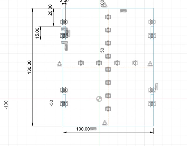
Here, I decided to be a little more specific with my design, so I created a rectangle, filleted the vertices, and subtracted the design from the acrylic to account the LCD screen.
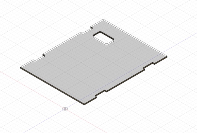
Here’s the acrylic top.
Next, I created an offset plane and began sketching the wooden frame, which would have the same width/length as the acrylic. To avoid typing out all the dimensions again, I used the project feature and selected the four slots. I extruded this new body and subsequently shelled it to get a hollow interior.
Next, I similarly extruded the four slots to serve as tabs for the acrylic.
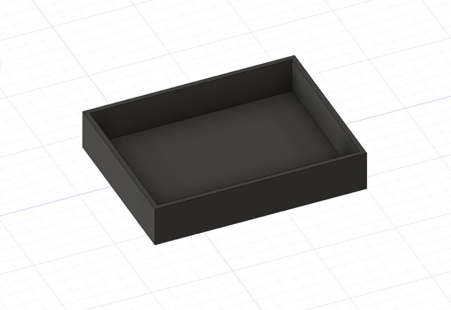
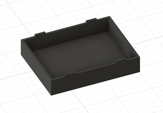
Wood frame before and after extruding the tabs
I created another new sketch and selected the interior wall of the frame as the plane. I drew an arbitrary rectangle and extruded it to cover the entire top. Afterwards, I added some of the more specific details: this included the locations of the sensors, the holder for the LCD screen, and the opening for cables on the side of the box.
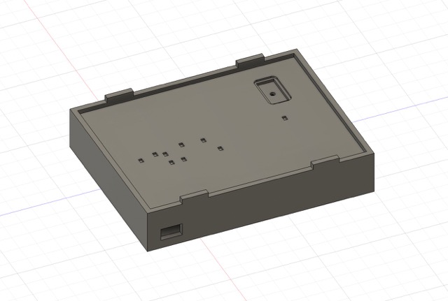
Note from post-week Angelina: why is the color so inconsistent? One can only wonder..
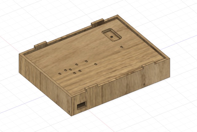
To finalize the wood frame, I used the appearance feature to make it resemble the final product. I ended up choosing oak wood as the design.
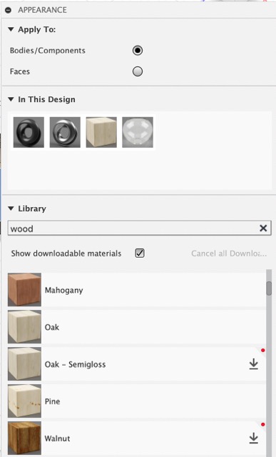
Here is the selection of wood appearances in Fusion360.
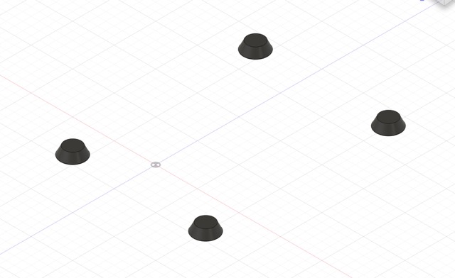
Next, I needed to design the rubber feet. Starting with two offset planes beneath the wooden frame, I sketched two concentric circles and used the rectangular pattern command to replicate it for each corner. Finally, I applied the loft command and shelled the bottom side.
Last but not least, I made all bodies (acrylic, wood frame, and rubber stops) visible to simulate how the different layers of the project would look together.
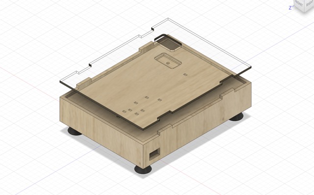
Here is the temporary model of my final project in Fusion360.
Modeling Wire Mounts in Fusion360
As an additional goal for the assignment this week, Mr. Dubick had students design a specific component in three different applications. I chose to design a wire mount for my cable management, as there will be a lot of wires from the LCD screen, neopixels, sensors, etc.
I got this idea after looking at Teddy Warner’s final project, where he made mounts for his jumper wires. The entire premise of the design is similar to his, excluding some stylistic choices.
Reviewing the timeline of Teddy’s design, I created the center component of the mount first. I tried to use more reasonable dimensions this time around, but a lot of it was still arbitrary. My biggest issue during this process was being efficient: I often felt like the methods I was taking were more time consuming than necessary.
To create the ridges, I drew one 3 pt. arc and applied the rectangular pattern command to replicate it. The resulting edges were too sharp, so I added a fillet to each intersection.
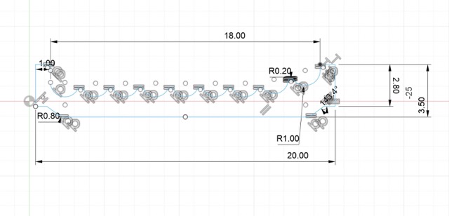
Here’s the initial sketch of the middle component; it’s an absolute mess.
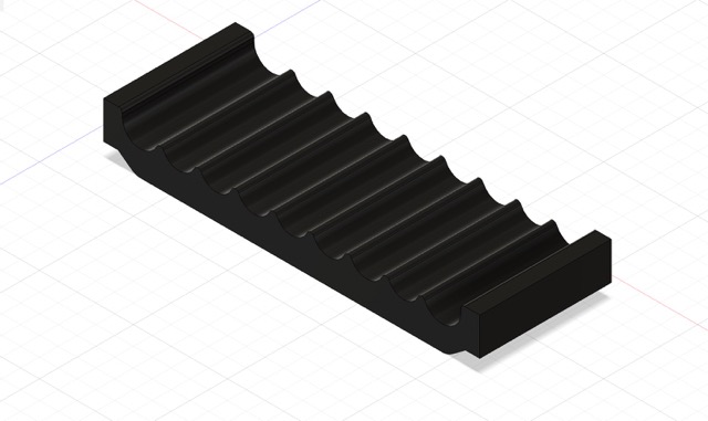
I extruded the sketch by 7 mm. Here, I realized that my design was oriented the wrong way, so I used the move tool to rotate it to make the ridges face down.
After making those changes, I had to design the side components of the mount. The sides were going to be how the mount fastens to the interior of the frame. In a new sketch, I started by using the project feature again, selecting the previously extruded body. I drew a 4 mm line on the top and bottom, followed by a tangent arc. In the center of the arc, I also added a 3.5mm diamter circle. To duplicate the design to the other side, I drew a construction line in the center of the middle component to serve as a mirror guideline.
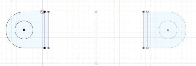
Here is the mirrored sketch of the side component.
All was left was to extrude that sketch and make some stylistic changes, such as adding chamfers.
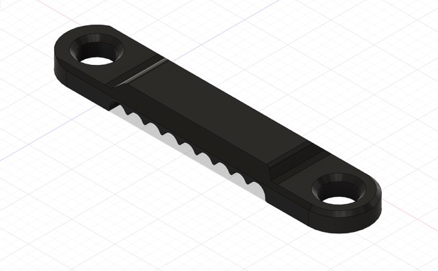
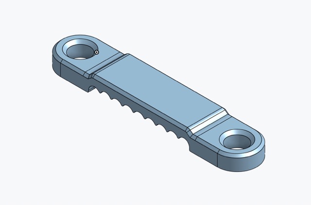
Here’s what the final wire mount in Fusion360 looked like.
Thoughts on Fusion360
Because I used Fusion360 previously in my engineering classes, I was already used to the commands and the interface. I find Fusion360 flexible, efficient, and forgiving. I like how the workspaces are organized, as well as how easy it is to find all of the features (i.e. the timeline). These benefits significantly expedited the process of designing the project model and the wire mounts.
2D Design
Gimp
Type of application: 2D raster program
For the 2D rastering portion of this week, I decided to try out Gimp, specifically its background removing capabilities. I started by importing the following image into Gimp:

Here’s the image I selected.
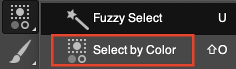
To quickly remove backgrounds from drawings with few colors/intracacies, I used the select by color feature, found in the toolbar. This automatically selects all portions of an image with a specific color.
Then, to get rid of the background, I just used the eraser tool and went over the selected area.
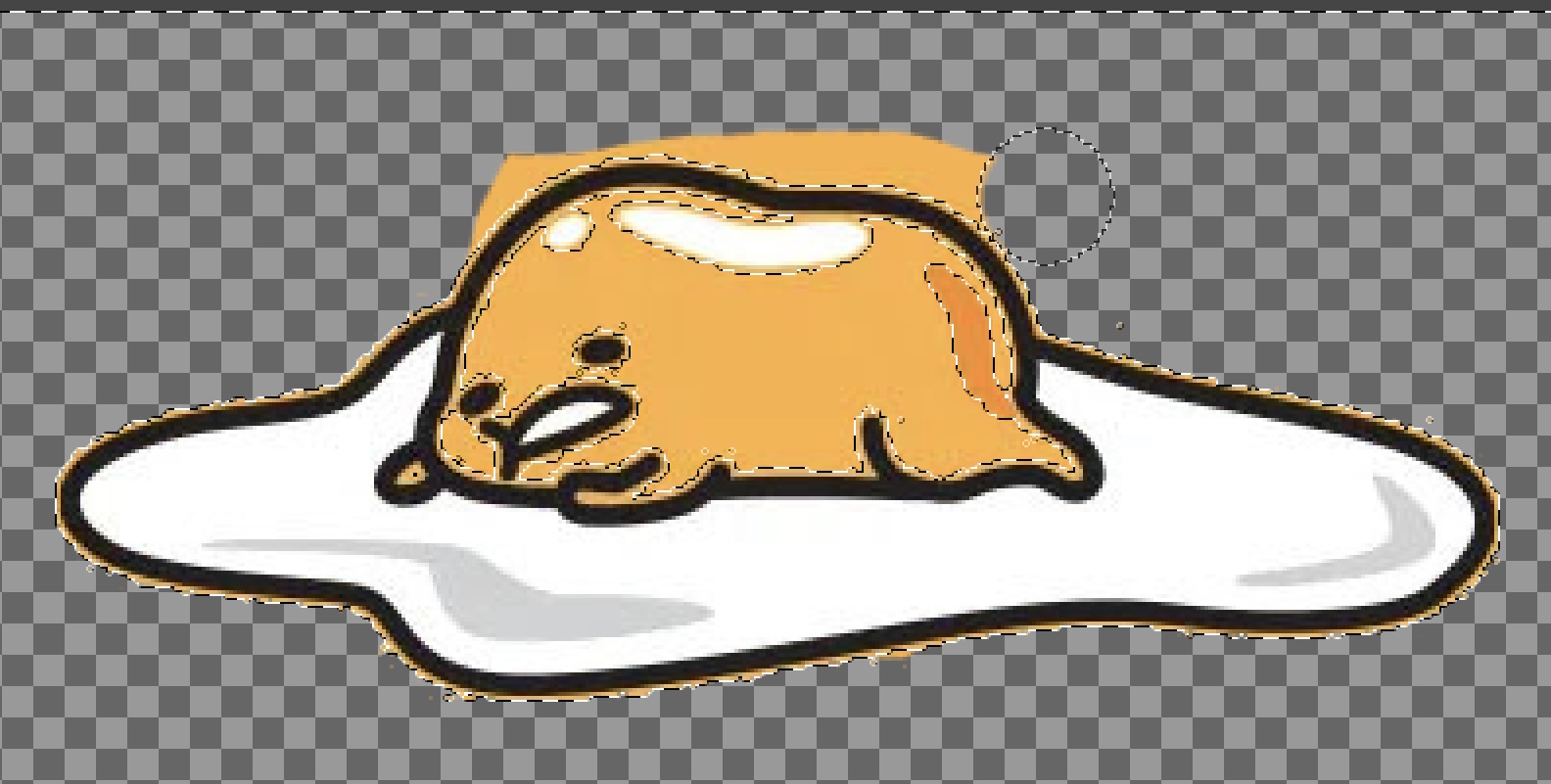
Erasing the background of gudetama
There were still tiny bits of yellow from the background in the black outline, so I went back in with a smaller-sized brush to get rid of them.

Image after fully removing the background
Thoughts on Gimp
For a free program, Gimp has a lot of powerful tools that are pretty easy to use! I enjoyed experimenting with the different tools and checking out the various ways to remove a background. The only downside is that it is a bit difficult to use on a macbook, as it wasn’t letting me easily scroll in and out.
Cuttle
Type of application: online vector design software
The third application I used was Cuttle, which is a vector based software. To begin learning how to use this program, I referenced previous graduates and the tutorials they used. I started out by creating a dodecahedron candle holder with a pentagon base.
One of cuttle’s main features involves geometry snapping, in which the user can easily snap together a selected point and a corner of a polygon, for example. This was different than previous vector softwares I used, and while it could be helpful at certain times, I found it to be less convenient than other design programs.
To create the dodecahedron, I first dragged and dropped a polygon onto the workspace, scaling it up to my desired size. I similarly added a rectangle afterwards, before applying the rotational repeat modifier with five repetitions. Grouping the rectangles and the pentagon with the boolean union, found under the modify tab, I colored the outline of the polygon red to indicate scoring.
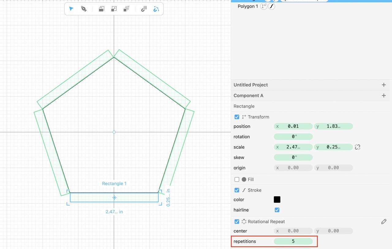
Here’s what the pentagon with rectangular flaps looked like in Cuttle.
For the actual design of the candle holder, I used the pen tool to draw bezier curves and experimented with stars/circles to my liking. To adjust the handles independently, I held the option key.
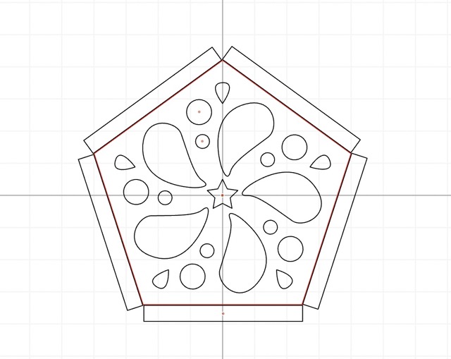
Thoughts on Cuttle
Overall, I thought the software was pretty easy to use, and there wasn’t anything particularly confusing about the interface. The major drawback, however, is that its simplicity can be very limiting (lack of tools, limits on customization, etc.), especially when projects become increasingly complex and multi-faceted. If you want to design a simple component to laser-cut, this application is sufficient; otherwise, I would prefer alternative vector programs, such as CorelDraw.
3D Design
OnShape
Type of application: Web-based CAD software
Next, I wanted to explore OnShape, an online CAD program. When I opened up a new project, I thought that the interface wasn’t too overwhelming as there were a lot of similarities to Fusion360. I messed around with the different commands, exploring how to create sketches/objects, add features, etc. This website was super helpful in finding certain aspects in the interface!
While experimenting with the features, I figured out how to constrain my sketches and how to apply the coincident feature to align shapes with the center point.
Note about constraints: Blue indicates that the sketch is not fully constrained (can still be moved/adjusted), while black indicated that it is constrained.
Because I wanted to try out more features in OnShape, I also made a twisted connector following this tutorial. I learned how to mirror components, bridge curves, and draw tangent arcs.
I sketched out and extruded a basic shape with a tangent arc, before mirroring it to the other side. I applied the transform feature to the mirrored body, rotating it 90º.
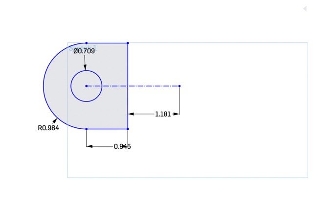
Here is the initial sketch of the connector.
Now, I needed a way to connect them. To do this, I applied the bridge curve command to the side edges, making sure that the “match tangent” option selected.
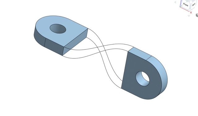
Here’s the connector with the four bridge curves.
To finish, I selected the “fill” option in the tool-bar and clicked each of the newly-created bridge curves.
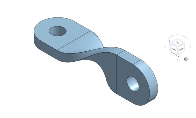
Here is the final twisted connector.
This design was mostly successful, except for when I tried to use the enclose feature on the bridged curves. Despite selecting all surfaces, as instructed by the video, I kept getting this error:
Enclose 1 did not regenerate properly: Selections do not enclose a region.
Designing Wire Mount in OnShape
Now that I have learned how to use Onshape, Mr. Dubick challenged us to design the same component–in this case, I designed the wire mount.
Here’s the final wire mount; I followed the same process as before while designing this.
Thoughts on Onshape
I liked this software a lot because of its resemblance to Fusion360. The interface was easy to use, and there weren’t any aspects I was particularly unfamiliar with. Nevertheless, I found manually clicking view normal to sketch plane each time I create a sketch a little bit redundant and annoying (for reference, in Fusion, it automatically reorients to that view). Managing assemblies and processes can also be frustrating at times. Overall, I would use this application again in the future!
FreeCad
Type of application: 3D modeling software
The last software I used was Freecad, a free downloadable 3D modeling software. After I downloaded and opened the application, I was immediately taken back by the interface: the main menu had a lot of content, and the toolbar had many icons I didn’t recognize.
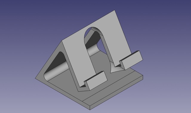
With the help of this tutuorial, which guided me through making a phone holder, I was able to learn some of the basic features.
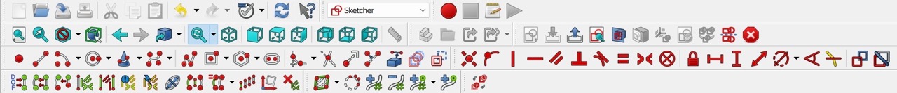
Creating a new sketch in the YZ plane, I drew an equilateral triangle using the line tool, angle constraints, and the vertical distance constraint. I also used the parallel constraint to create an offset triangle on the inside of the original triangle. Then, I sketched out the hook for the phone to sit on, using the perpendicular and distance constraints until I was satisfied. The tutorial made the process a lot easier, but setting up these constraints was still a hassle.
Here’s the sketch of the phone holder, side profile
Instead of having the extrude tool like in Fusion360 or OnShape, FreeCad uses a feature called “Pad.” I used this tool to convert my sketch into a 3D body.
The next part of the tutorial involved creating a pocket through the front and back. To do this efficiently, I created a datum plane on the front of the phone holder and designed a 25 mm wide slot. When I used the pocket feature, it subtracted the slot from the front and back.
Here’s what the phone holder looked like after pocketing the slot.
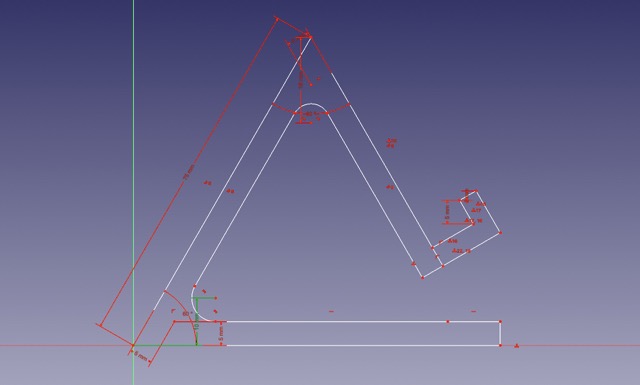
The very last thing to do was to add 1.5 mm fillets to any sharp edges.
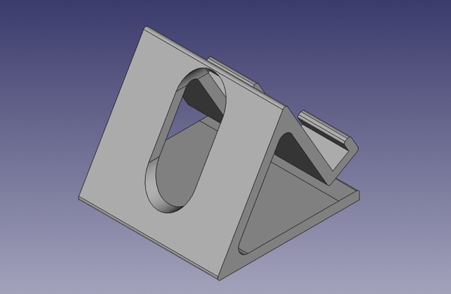
Here is the final phone holder.
Modeling Wire Mounts in FreeCad
Similar to OnShape, I tried to model wire mounts in FreeCad. Unfortunately, I wasn’t even able to create a cohesive sketch due to the confusing interface and the overwhelming amount of options. Additionally, the sketch I created initially was completely red, indicating that it was over-constrained. In the future, I won’t be using this software.
Thoughts on FreeCad
Out of all the software I tried out this week, FreeCad was certainly the most difficult to use. Not only were the commands hard to find, but it also took me quite a while to set up the constraints. The interface isn’t very intuitive or user-friendly in general, which ultimately led to my failure in designing the wire mount. However, for a free program, I still think FreeCad has a lot of features and can be very useful- just maybe not for me.
Gravity Sketch
Type of application: 3D modeling and design software
As an additional CAD program, Mr. Dubick and fellow teacher Mrs. Walthall-Eisman provided VR sets to all of the students to test out Gravity Sketch.
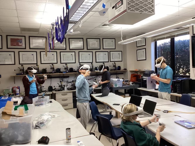
Here is everyone using gravity sketch in the VR headsets.
After loading up the VR set and opening a new project on Gravity Sketch, the first thing I did was test out the different modeling features and 3D object options. I ended up designing this simple face using a sphere, a cone, and the point drawing tool.
Workflow for exporting gravity sketch files
-
On home menu of gravity sketch, click on LandingPad, login to your email (log in without password)
-
Click on
magic link -
Open the email account and click
Activate Magic Link -
Create a 3D sketch in gravity sketch
-
Enter the menu by clicking the button with three lines
-
Go to the
save and exporttab on the right side of the screen -
On the bottom, click the toggle under
save to deviceuntil it sayssave to LandingPad -
Ensure that the file is exported as an .OBJ, select welded and render; when it has sent, the controller linked to your left hand will indicate that the file has successfully exported
-
Open landingpad.me on your computer
-
Sign in using the same email and magic link again
-
Export your file from landingpad.me onto your computer for personal use
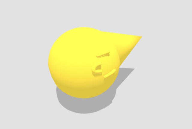
Here’s what my design in Gravity Sketch looks like.
I exported the file as a .obj file, and I imported it in a slicing application called PrusaSlicer. Slicing a 3D model translates the design in a language that a 3D printer can understand (defined by the x, y, and z plane).
I applied default settings, such as .20 mm SPEED and Prusament PLA for the filament.
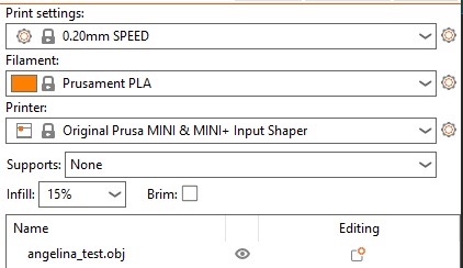
Here’s what my settings looked like in PrusaSlicer.
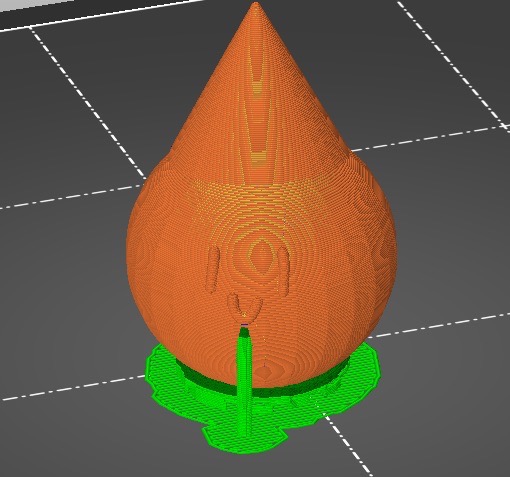
Here’s what the file looked like in PrusaSlicer after slicing (with supports). He’s just a little guy.
The last thing to do was upload the g-code (file type after slicing) to the Prusa websites, which were connected to the 3D printers. The total print took around 40 minutes.
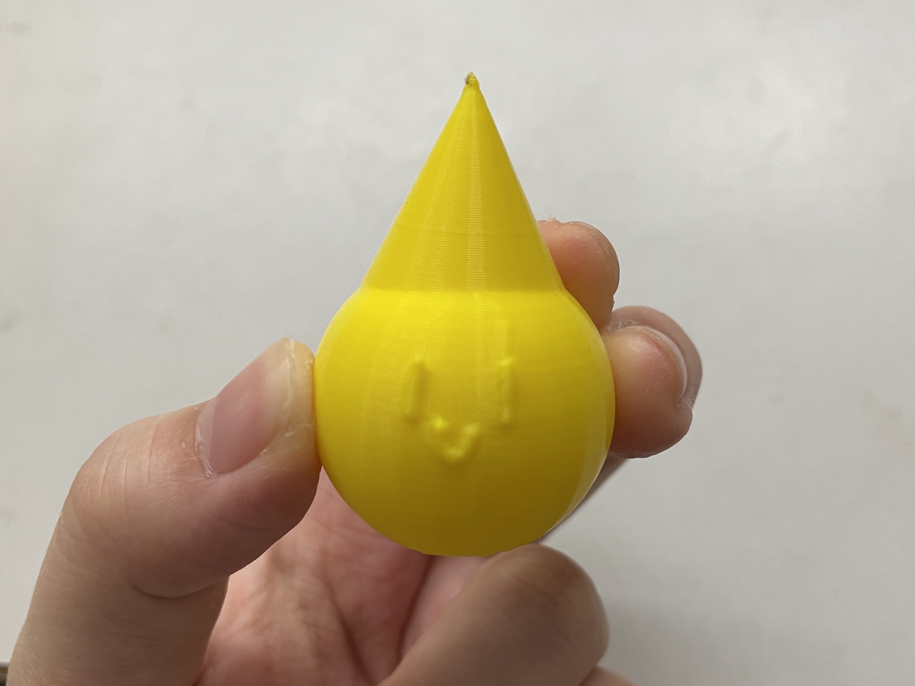
Here’s what the final print looks like!
Thoughts of Gravity Sketch
Although some of the features were limited and not as versatile as Onshape or Fusion360, I still loved testing out cadding in a virtual reality environment! Using the controllers and physically changing the orientation was such a cool experience; it was also fun watching my peers play around with it. Overall, I think gravity sketch has a lot of potential, and I’m excited to use it more in the future. Thanks again to Mr. Dubick and Mrs. Walthall-Eisman for letting us have this unique opportunity!
Week 2 Reflection
To say the least, this week was both challenging and rewarding. I thoroughly enjoyed experimenting with the different CAD programs, such as Gimp, Onshape, Cuttle, etc. on top of using Fusion360, which I was more familiar with. Out of the new programs I tested out, my favorite is definitely Onshape: not only was the interface user-friendly, but the toolbar was accessible and didn’t clutter the screen. However, I also really enjoyed Gravity Sketch, as it was the most memorable and unique CAD software I tried this week. I’m looking forward to the next week!