Final Project
Final Project Slide
Final Project Video
License
This work is licensed under the Creative Commons License-NonCommercial-ShareAlike, which allows others to “enables reusers to distribute, remix, adapt, and build upon the material in any medium or format for noncommercial purposes only, and only so long as attribution is given to the creator.”

Bill of Materials
| Component | Quantity | Source | Part Number | Cost | Available in lab? |
|---|---|---|---|---|---|
| 1/2” plywood | 1 | Home Depot | $68.88 | Yes | |
| One-sided FR-1 board | 2 | Bantam | $0.96 | Yes | |
| Adafruit Neopixel strip roll | 1 | Amazon | $14.99 | Yes | |
| VL53L1X Time of Flight sensor | 1 | Adafruit | $14.95 | Yes | |
| Seeed xiao RP2040 | 1 | Seeed Studio | 102010428 | $5.40 | Yes |
| ESP32 Wroom 32 | 1 | Amazon | 1904-1020-2-ND | $24.99 | Yes |
| Satin brass hinges | 4 | Home Depot | $2.93 | No | |
| 2.8” TFT LCD with ILI9341 | 1 | Adafruit | $29.95 | No | |
| Totalboat tabletop clear epoxy | 1 | Amazon | $59.99 | Yes | |
| Pearl white resin pigment | 1 | Amazon | $14.95 | Yes | |
| Latex primer (panda white) | 1 | Sherwin-Williams | $27.49 | No | |
| 1/8” clear acrylic sheet | 1 | Amazon | $7.99 | Yes |
Total Price: $273.47
Old Project Idea
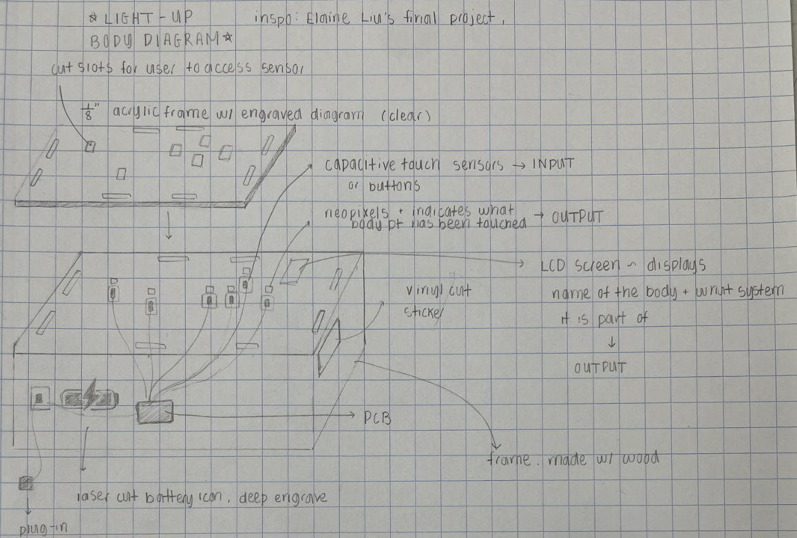
My original final project proposal was to create a light-up diagram of a body, using capacitive sensors or transistors as an input and an LCD/neopixels as an output. This project aims to benefit those who want to explore physiology but find conventional diagrams unengaging (me included!); by creating a more fun and interactive tool for the classroom, students of all ages can explore basic anatomy and learn about systems in the body!
I was inspired by Elaine Liu’s final project, Nadieh Bremer’s final project and one of my previous engineering projects from two years ago. At this point, a lot of aspects in my project are still tentative, but I have a general outline of what I want to achieve:
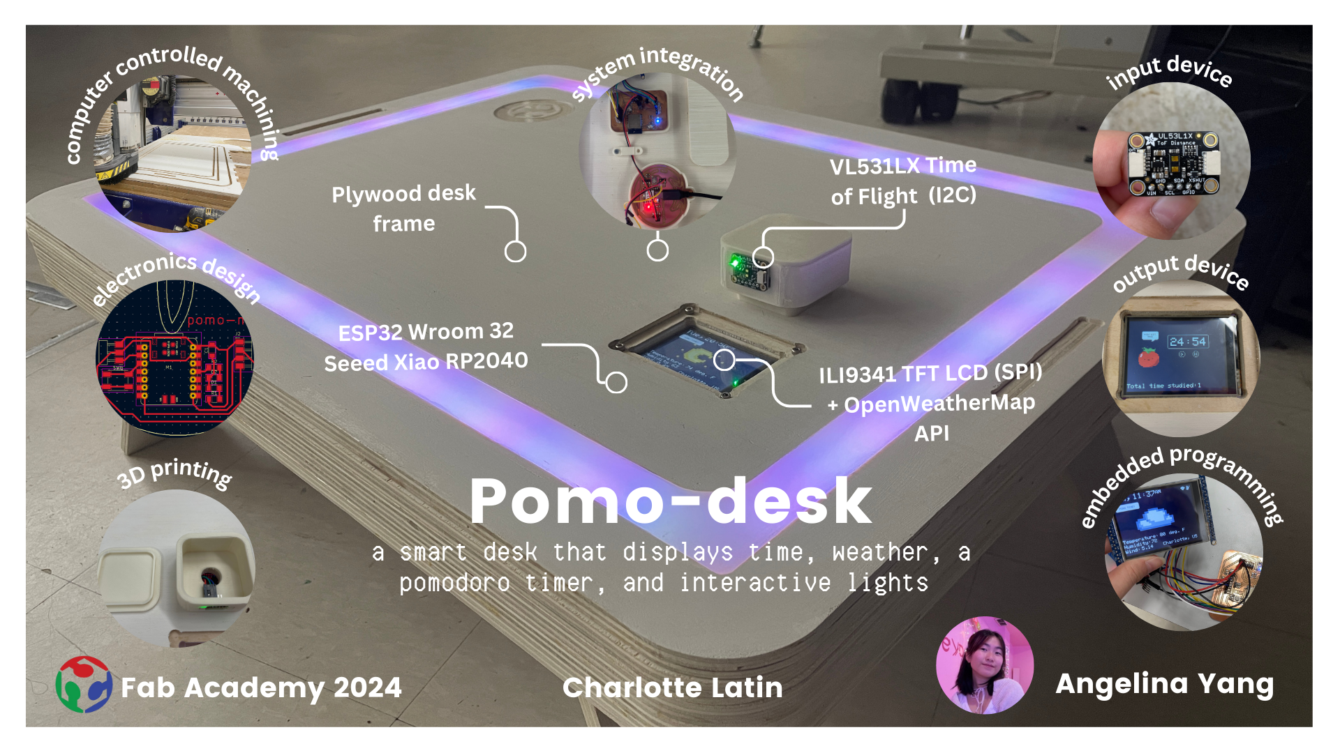
New Project Idea and Model
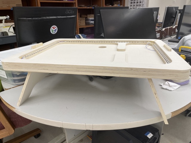
After considering the aesthetic aspect of my original project, as well as the lack of progress I’ve been making, I decided to restart on my brainstorming and choose different final project (week 7). My new approach was to choose something a bit more relevant to myself as a student. Thus, for my second project idea, I decided to create a portable smart desk with a built in pomodoro timer. This desk will contain three layers total–two wood layers serving as a frame, with a center layer made out of wood flexures and acrylic. I plan on having a neopixel shine through the acrylic.
| Method | How it will apply in my project |
|---|---|
| Week 2: Computer-aided design | I designed my project in my CAD program of choice; in terms of a project-specific component, I will design components for cable management and electronics housing |
| Week 3: Computer controlled cutting | I laser-cut a clear acrylic coaster to go on top of the desk |
| Week 4: Electronics production | I created the PCB I need to use for my LCD screen, neopixels, etc. (2 boards) |
| Week 5: 3D scanning and printing | I 3D printed out components for electronics housing and cable management |
| Week 6: Electronics design | I designed custom boards needed for neopixels, TOF, and LCD and created a plan for how to wire the neopixels and the LCD screen |
| Week 7: Computer controlled machining | I used the CNC shopbot to design the main frame of the desk |
| Week 8: Embedded programming | I programmed the TOF to turn on the neopixels when an individual is nearby |
| Week 10: Input devices | I programmed the TOF to work in conjunction with the neopixels; I programmed touch on the tft lcd |
| Week 11: Output devices | I programmed the neopixels on the interior of the desk |
| Week 13: Networking | I used openweathermap API alongside the ESP32 wroom 32 to display weather information in real time |
| Week 15: Interface and Application Programing | I designed the interface of the LCD screen with custom bitmaps |
System Diagram and Gantt Chart
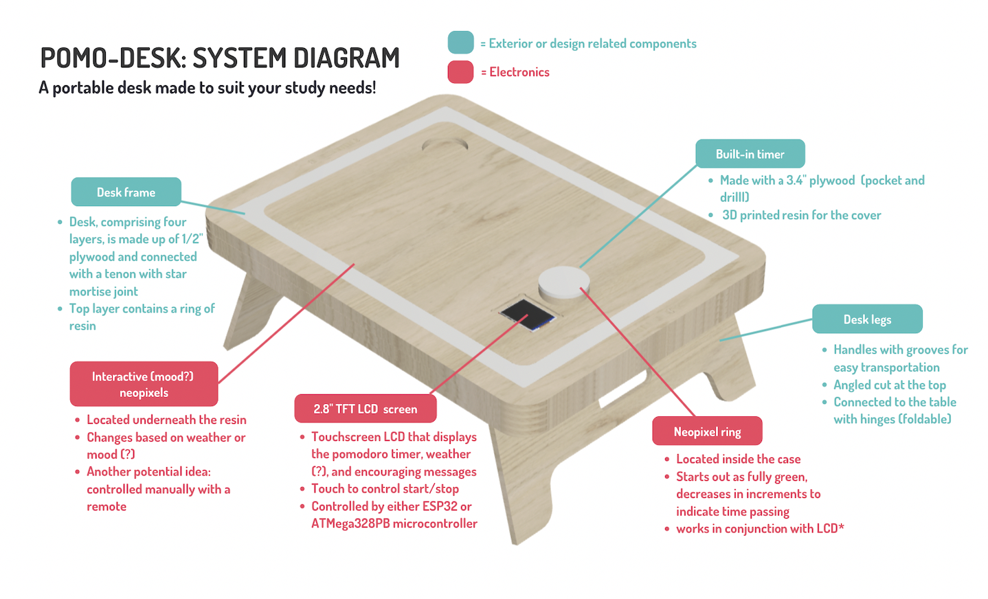
I created this system diagram to visualize the application of each process in the final product. The TFT LCD model was taken from GrabCad.
Original model was created during CAD week
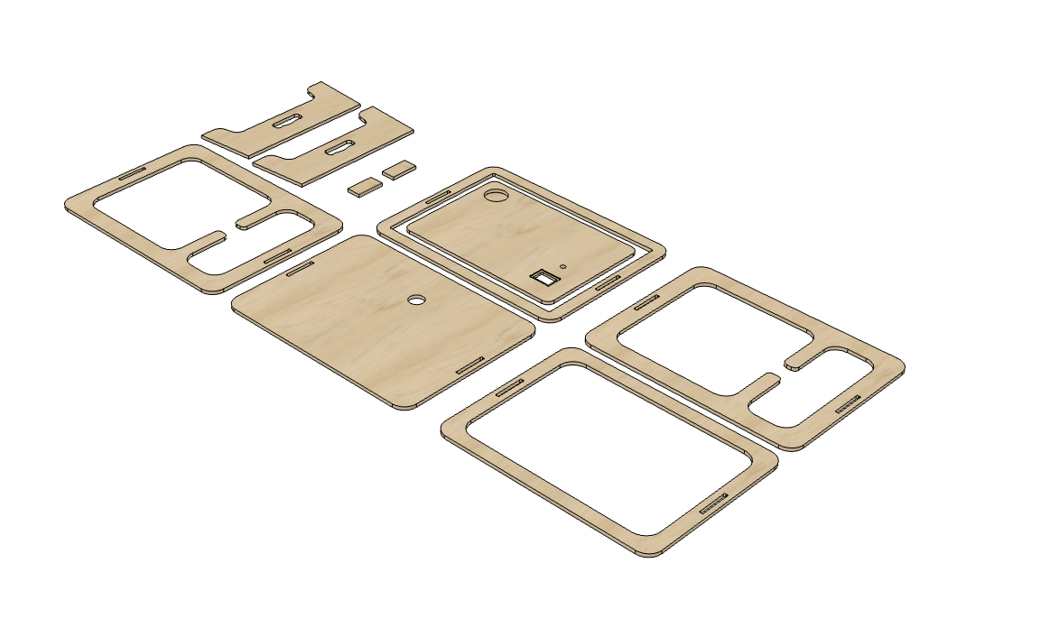
My original idea was to have three layers, with a channel in-between for the acrylic to slide into. This was ultimately a failed idea and mainly existed as a driver for my project. I ended up remodeling so that the wood would layer, and the neopixels would shine up, as opposed to outwards. I CADded this design in Fusion360.
I also designed this gantt chart during midterms to determine what tasks I needed to complete leading up to June:
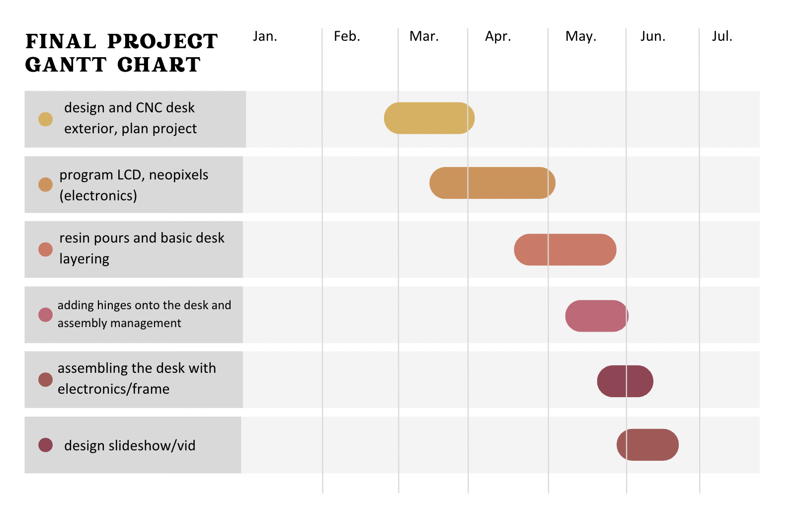
Note from future Angelina: this was a very optimistic plan :,D
I also created a list of tasks to be completed at this point:
x determine the full extent of features with the lcd
x test the touch capabilities on the lcd (preferably inputs week)
x choose microcontroller for lcd - between the atmega328 or the ESP32 (works with wifi)
x design the lcd PCB and test
x design the rp2040 PCB for the neopixels surrounding the interior
x sand down the desk and make sure that the key fits (too thick as of now)
x paint the contact points of the wood with epoxy
x do the resin pour on the top layer and polish
x design and 3d print top for timer case
x callibrate everything
x assemble everything (add hinges too)
Desk Frame
Designing the Desk in Fusion360
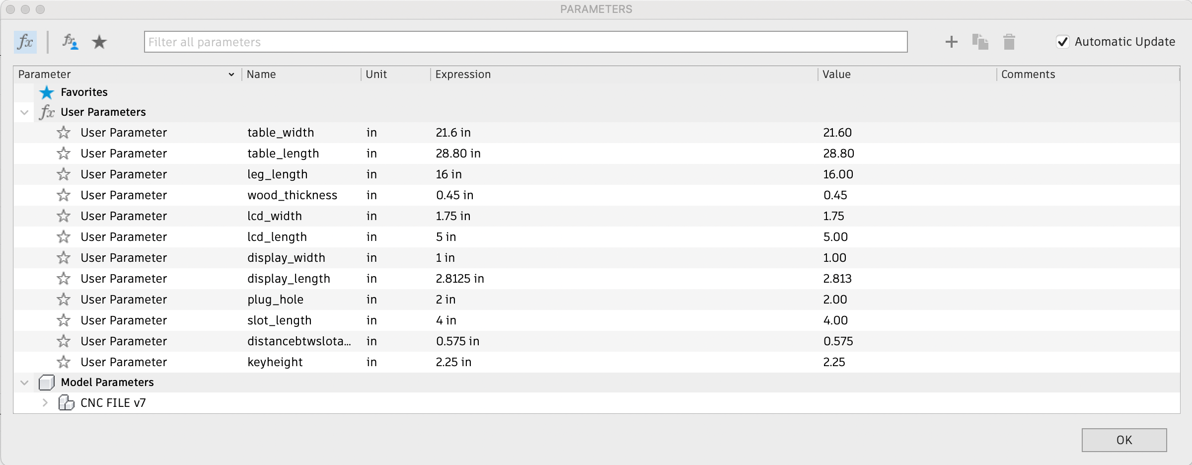
I began designing my sketch in Fusion 360, creating a list of parameters. My design was originally a lot bigger, but given the design constraints, I had to scale it down by at least 60%.
Structure Description:
-
Bottom layer: serving as a base for the table, contains a hole for the cable
-
2nd layer: offset outline based on the bottom layer with two compartments outlined for electronics housing
-
3rd layer: offset outline based on the bottom layer, distance slightly smaller to create a lip for the neopixels
-
Top layer: offset outline based on bottom layer, center piece with a pocket for cup holder, hole for timer wiring, and a pocket/profile for the LCD screen; the channel will be filled with resin
-
Legs: legs will be fastened onto the bottom of the table with hinges
-
Rectangular key: will slot into the sides of each layer to keep the table together
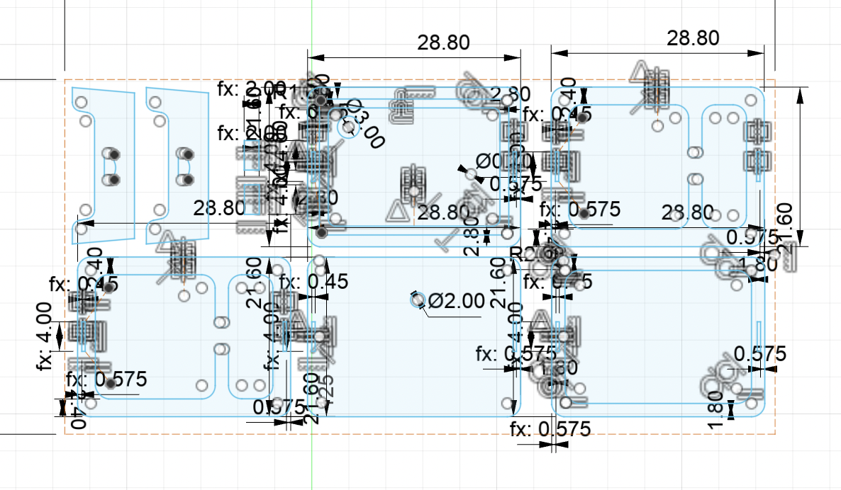
Here are the parameters of the scaled down version:
I extruded by the material thickness, around .45” and created a pocket for the LCD screen and the cup holder by .125”.
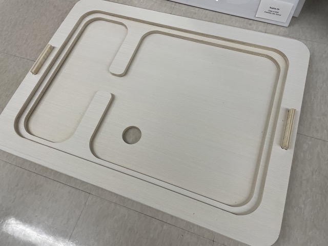
CAM and Milling
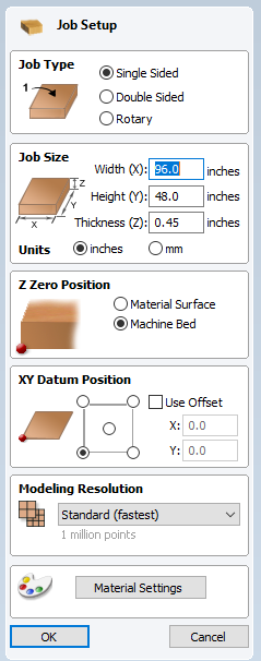
After adding the dogbones extension I found in week 7, I exported as a .dxf and pulled the design into Aspire. I configured the job setup according to the bed size (96” x 48”) and thickness of material. I selected the machine bed as the z zero position.
In the main workspace, I created three toolpaths, including a profile, a pocket (.125” deep), and a cut-through pocket (.45” deep).
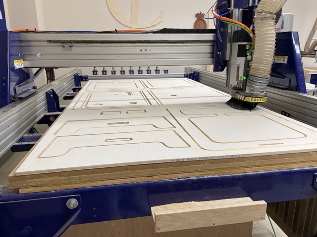
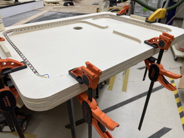
As mentioned in my week 7 documentation, the top piece was slightly messed up, so I created a new toolpath and remilled it. Here is what it looks like all milled out:
For more documentation, refer to Computer Controlled Machining week.
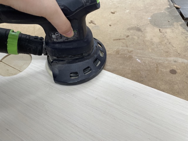
I post-processed my boards afterwards with the orbital sander (180-330 grit sandpaper).
Resin
After discussing with Mrs. Morrow about what type of resin would work best for a .5” pour and approximately 1200 mL volume, she suggested the Totalboat Tabletop Epoxy (1A:1B). We were initially considering the Totalboat Thickset epoxy, but we concluded that it was too runny and inconvenient to use in a short time frame.
Sealing the Wood
The first thing I had to do was seal the edges of my wood that would come in contact with the resin. This ensures that the resin won’t sink and affect the wood. For this, I also used the Totalboat Tabletop Epoxy.
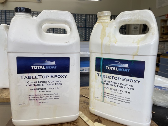
After mixing for 5-7 minutes, I simply painted this over the edge and left it to set for 24 hours.

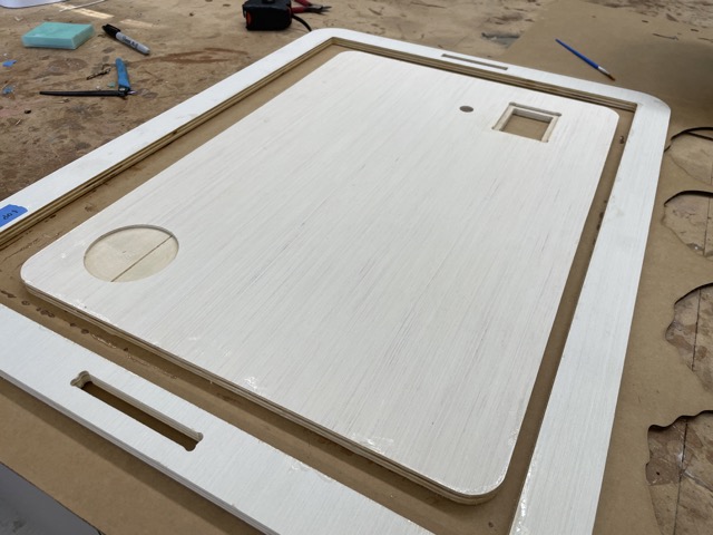
When I went to check on it the next day, I noticed that parts of the cardboard were stuck to it, so I ran the orbital sander with 220 grit sandpaper over it a couple of times.
Pouring and Polishing the Resin
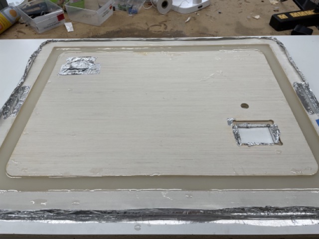
The lab had recently gotten aluminum foil tape, and I wanted to see how effectively it could protect the wood from the resin. I simply ripped off a large portion and wrapped the perimeter in it. I also covered the slots and the area for the screen in tape.

Note: to ensure that the distance between the center piece and the outer ring was consistent all the way around, I laser cut a cardboard spacer and used it as a reference.
Because the tabletop epoxy undergoes a exothermic reaction when it sets, I needed to do a 2-3 layer pour over a few days. I initially started out with 200g of part A and 200g of part B (first two layers), mixing in a small spoonful of pearl white pigment before moving to 60g of A to 60g of B to create the finish. After each pour, I used the heat gun to briefly remove the air bubbles within the resin.
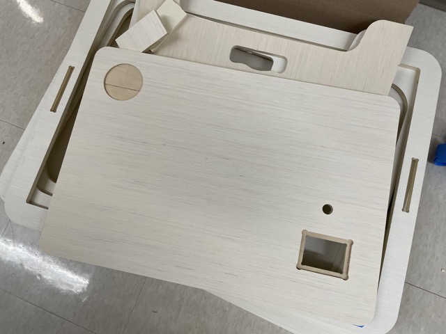
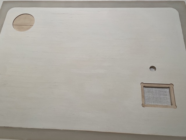
Once the resin was set, I again used the heat gun to remove parts of the foil that had stuck to the resin. Then, I used a mallet and a chisel to remove the entire piece off of the melamine board. Thankfully, the resin didn’t stick to the board, so I was able to get it off relatively easily. However, some of the resin did flow underneath the wood, causing it to be slightly uneven at some parts. To fix this, I simply ran the wood underneath the drum sander with the help of Mr. Budzichowski. Additionally, I applied a white primer, since sanding the wood resulted in its yellow undertones coming through. Here is what the top looked like after:
For more information, visit Computer Controlled Machining.
Electronics
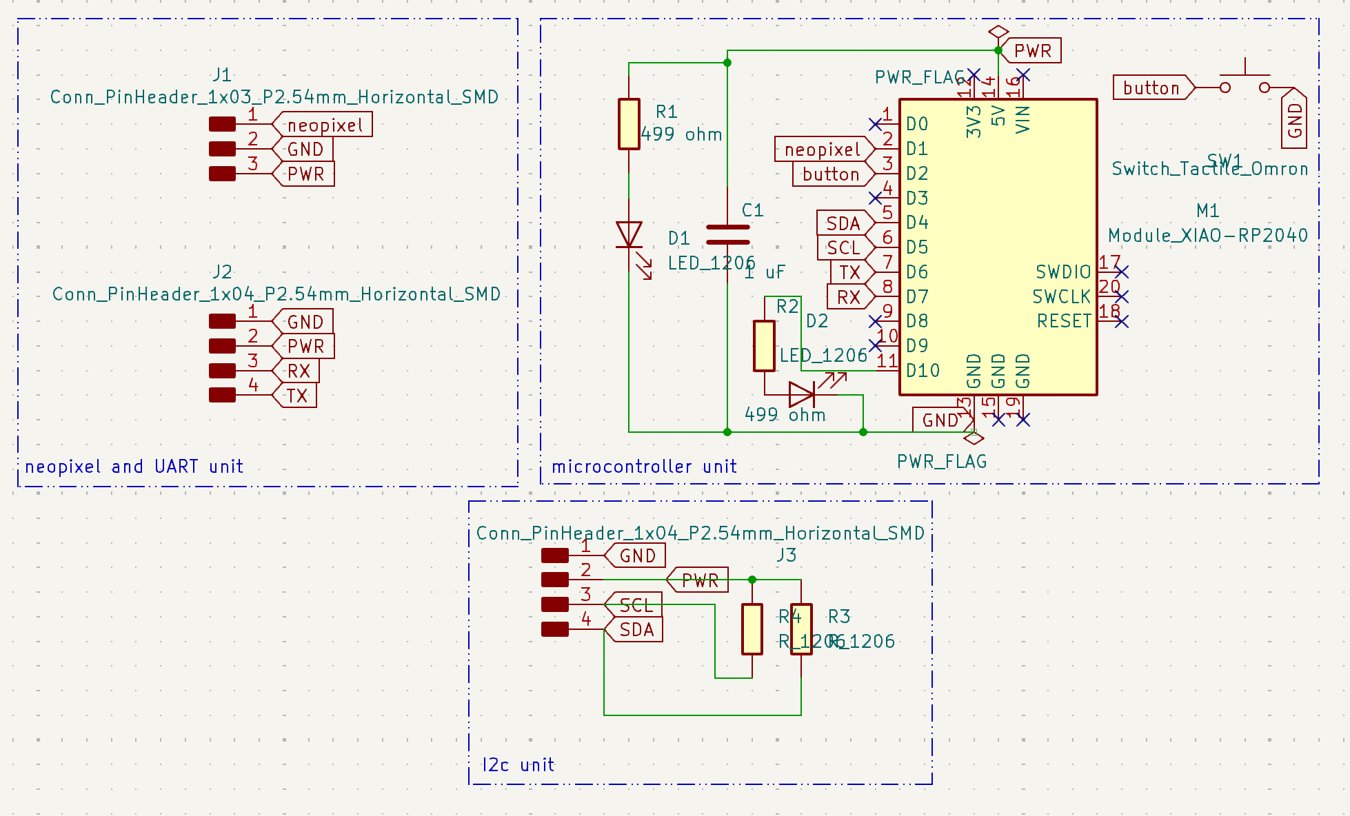
RP2040 Tomato Master Board
For my main board, I designed a board using the seeed xiao RP2040 that could support I2C and had headers for neopixels too.
Pomo-master Board:
For the edge cuts of my board, I wanted to do a design that related to my final project, similar to how Teddy Warner created aqua-ponics related boards. Thus, I searched online for a .svg of a tomato, since tomatos are often associated with the pomodoro technique. I scaled this file up in Fusion360, before returning to Kicad and selecting File>Import>Graphics. To create the outside shape as well as the interior details, I created two .dxf files and subsequently inserted them onto the edge cut and silkscreen layers. Because the original .svg file was too small, I had to scale up the design by 1.65x to fit the board.

Once I finished designing, I plotted and saved my KiCad files as Gerbers and imported them into the Bantam software. I selected the 1/64” and 1/32” bits, set z-material offset as .01 and ran the jobs.
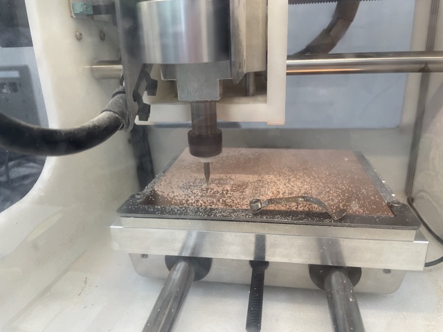
Afterwards, I applied kapton tape onto the back of the seeed, and I soldered on the following components onto the board:
| Component | Quantity |
|---|---|
| Seeed Xiao RP2040 | 1 |
| SMD red LED | 2 |
| 4-pin SMT vertical male header | 1 |
| 3-pin SMT vertical male header | 1 |
| 499 1206 SMD resistor | 2 |
| 970 nF capacitor (~1uF) | 1 |
| Milled PCB | 1 |
| Tactile push button | 1 |
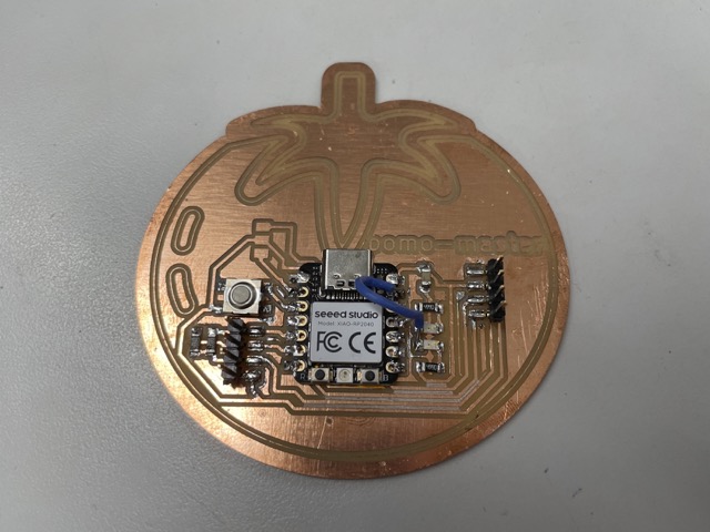
I ended up swapping out the jumper with a more flexible wire.
For more information, visit Networking and communications.
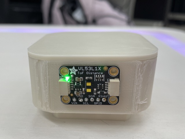
Programming a VL53L1X Time of Flight
I wanted my desk to be more interactive, so I decided to include a vl53l1x time of flight sensor, inspired by Alana Duffy. This sensor measures the amount of time it takes for a portion of emitted light to return to the emitter - or in other (simpler) words, it can sense the distance of an individual or an object. I planned on using this to make the desk more aware of when someone is near (inspiration from Sands Fish).
In Arduino IDE, I downloaded the VL531LX library by Polulu and opened up the Continuous example. In terms of the wiring, I simply connected the following pins:
-
SDA to SDA
-
SCL to SCL
-
GND to GND
-
VCC to 5V
/*
This example shows how to take simple range measurements with the VL53L1X. The
range readings are in units of mm.
*/

#include <Wire.h>
#include <VL53L1X.h>

VL53L1X sensor;

void setup()
{
  while (!Serial) {}
  Serial.begin(115200);
  Wire.begin();
  Wire.setClock(400000); // use 400 kHz I2C

  sensor.setTimeout(500);
  if (!sensor.init())
  {
    Serial.println("Failed to detect and initialize sensor!");
    while (1);
  }

  // Use long distance mode and allow up to 50000 us (50 ms) for a measurement.
  // You can change these settings to adjust the performance of the sensor, but
  // the minimum timing budget is 20 ms for short distance mode and 33 ms for
  // medium and long distance modes. See the VL53L1X datasheet for more
  // information on range and timing limits.
  sensor.setDistanceMode(VL53L1X::Long);
  sensor.setMeasurementTimingBudget(50000);

  // Start continuous readings at a rate of one measurement every 50 ms (the
  // inter-measurement period). This period should be at least as long as the
  // timing budget.
  sensor.startContinuous(50);
}

void loop()
{
  Serial.print(sensor.read());
  if (sensor.timeoutOccurred()) { Serial.print(" TIMEOUT"); }

  Serial.println();
}
When I uploaded this to the tomato board, the serial monitor stated Failed to detect and initialize sensor!, indicating that either the sensor was bad or the board had an issue. To begin troubleshooting, I decided to first test the ToF with a basic Arduino Uno.
I wired the Arduino to the ToF in a similar way and uploaded the exact same code.
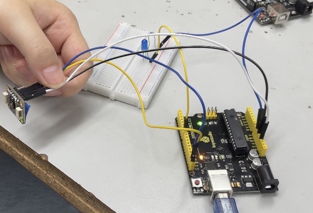
After uploading, I got values ranging from 10 to ~300 mm, meaning that the sensor was working. Confused, I looked towards previous documentation for help. From Alana’s and Adam Stone’s documentation, which suggested the following steps:
-
plug in without bootloader button
-
select board + board
-
upload (it will fail)
-
unplug
-
plug in while holding bootloader button
a. select the UF2 document in the pop-up
-
select UF2 Board as the upload port
-
upload
-
select the new port which will be COM something
-
open the serial monitor (if applicable)
When I followed these steps, I was able to easily upload the code to the seeed and get the ToF working!
Programming the Neopixels to Respond to Distance
#include <Adafruit_NeoPixel.h>
#ifdef __AVR__
 #include <avr/power.h> // Required for 16 MHz Adafruit Trinket
#endif

// Which pin on the Arduino is connected to the NeoPixels?
// On a Trinket or Gemma we suggest changing this to 1:
#define LED_PIN     27

// How many NeoPixels are attached to the Arduino?
#define LED_COUNT  100

// NeoPixel brightness, 0 (min) to 255 (max)
#define BRIGHTNESS 50 // Set BRIGHTNESS to about 1/5 (max = 255)

// Declare our NeoPixel strip object:
Adafruit_NeoPixel strip(LED_COUNT, LED_PIN, NEO_GRBW + NEO_KHZ800);

#include <Wire.h>
#include <VL53L1X.h>

VL53L1X sensor;

void setup()
{
  while (!Serial) {}
  Serial.begin(115200);
  Wire.begin();
  Wire.setClock(400000); // use 400 kHz I2C

  sensor.setTimeout(500);
  if (!sensor.init())
  {
    Serial.println("Failed to detect and initialize sensor!");
    while (1);
  }

  // Use long distance mode and allow up to 50000 us (50 ms) for a measurement.
  // You can change these settings to adjust the performance of the sensor, but
  // the minimum timing budget is 20 ms for short distance mode and 33 ms for
  // medium and long distance modes. See the VL53L1X datasheet for more
  // information on range and timing limits.
  sensor.setDistanceMode(VL53L1X::Long);
  sensor.setMeasurementTimingBudget(50000);

  // Start continuous readings at a rate of one measurement every 50 ms (the
  // inter-measurement period). This period should be at least as long as the
  // timing budget.
  sensor.startContinuous(50);
  strip.begin();           // INITIALIZE NeoPixel strip object (REQUIRED)
  strip.show();            // Turn OFF all pixels ASAP
  strip.setBrightness(BRIGHTNESS);
}

void loop()
{
  int val = sensor.read();
  Serial.print(sensor.read());
  if (sensor.timeoutOccurred()) { Serial.print(" TIMEOUT"); }

  Serial.println();
  if (val <400) {
    rainbow(.0001);
  } else {
    for (int i = 0; i<255; i++){
      strip.setPixelColor(i, strip.Color(0, 0, 0));
    }
    strip.show();
  }
}

void rainbow(int wait) {
  for(long firstPixelHue = 0; firstPixelHue <5*16384; firstPixelHue += 512) {
    strip.rainbow(firstPixelHue);
    strip.show();

  }
}
ESP32 Wroom LCD Board
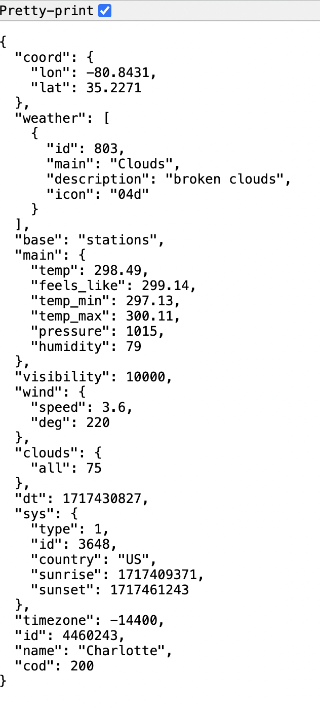
For the functionality of my ili9341 tft lcd, I wanted to include mainly two features: a main menu that displays time, location, temperature, and humidity, and an alternate page for the pomodoro timer. To do this, I decided to use the ESP32 Wroom 32 and OpenWeatherMap API. On the openweathermap website, I first created a new account and accessed my API key. Ensuring that active is toggled, I copied the api key and typed the following into a web browser: https://api.openweathermap.org/data/2.5/weather?q=CITY,COUNTRY&APPID=APIKEY, inserting my city, country, and api key into the appropriate locations (i.e. Charlotte, US). I used this to confirm if it was displaying relatively accurate information:
Seeing as it was working fine, I began working towards displaying it on my tft lcd. There wasn’t that much documentation on using the adafruit 2.8” screen with an ESP32 wroom, and there seemed to be several pins that could work with SPI, but I thankfully found Maharshi Bhattacharya’s documentation, who had used a similar model.
Here’s a detailed outline of the connections I found worked:
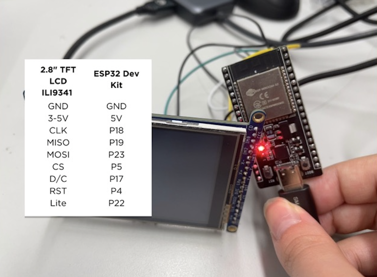
I uploaded the graphicstest example sketch under the Adafruit_ILI9341 library, defining the new pins and it worked!
From that point on, I wrote a code based off of the examples in the esp8266 weather station library. I also included the NTPClient library, which displays time.
#include <WiFi.h>
#include <HTTPClient.h>
#include <Arduino_JSON.h>

#include "SPI.h"
#include "Adafruit_GFX.h"
#include "Adafruit_ILI9341.h"
#include <NTPClient.h>
#include <WiFiUdp.h>

String weekDays[7]={"Sun", "Mon", "Tue", "Wed", "Thu", "Fri", "Sat"};
String months[12]={"Jan", "Feb", "Mar", "Apr", "May", "Jun", "Jul", "Aug", "Sep", "Oct", "Nov", "Dec"};
static const unsigned char PROGMEM image_weather_temperature_bits[] = {0x1c,0x00,0x22,0x02,0x2b,0x05,0x2a,0x02,0x2b,0x38,0x2a,0x60,0x2b,0x40,0x2a,0x40,0x2a,0x60,0x49,0x38,0x9c,0x80,0xae,0x80,0xbe,0x80,0x9c,0x80,0x41,0x00,0x3e,0x00};
static const unsigned char PROGMEM image_wifi_full_bits[] = {0x01,0xf0,0x00,0x07,0xfc,0x00,0x1e,0x0f,0x00,0x39,0xf3,0x80,0x77,0xfd,0xc0,0xef,0x1e,0xe0,0x5c,0xe7,0x40,0x3b,0xfb,0x80,0x17,0x1d,0x00,0x0e,0xee,0x00,0x05,0xf4,0x00,0x03,0xb8,0x00,0x01,0x50,0x00,0x00,0xe0,0x00,0x00,0x40,0x00,0x00,0x00,0x00};


#define TFT_DC 17
#define TFT_CS 5
#define TFT_MOSI 23
#define TFT_CLK 18
#define TFT_RST 4
#define TFT_MISO 19

WiFiUDP ntpUDP;
NTPClient timeClient(ntpUDP);

String alternative;

// If using the breakout, change pins as desired
Adafruit_ILI9341 tft = Adafruit_ILI9341(TFT_CS, TFT_DC, TFT_MOSI, TFT_CLK, TFT_RST, TFT_MISO);

const char* ssid = "CLSLabs";
const char* password = "clshawks";

// Your Domain name with URL path or IP address with path
String openWeatherMapApiKey = "e0f21e445c4ebf1aec3b6ebab38b7261";
// Example:
//String openWeatherMapApiKey = "bd939aa3d23ff33d3c8f5dd1dd435";

// Replace with your country code and city
String city = "Charlotte";
String countryCode = "US";

// THE DEFAULT TIMER IS SET TO 10 SECONDS FOR TESTING PURPOSES
// For a final application, check the API call limits per hour/minute to avoid getting blocked/banned
unsigned long lastTime = 0;
// Timer set to 10 minutes (600000)
//unsigned long timerDelay = 600000;
// Set timer to 10 seconds (10000)
unsigned long timerDelay = 10000;

String jsonBuffer;

void setup() {
  Serial.begin(115200);
  tft.begin();

  WiFi.begin(ssid, password);
  timeClient.begin();
  timeClient.setTimeOffset(-14400);
  Serial.println("Connecting");
  while(WiFi.status() != WL_CONNECTED) {
    delay(500);
    Serial.print(".");
  }
  Serial.println("");
  Serial.print("Connected to WiFi network with IP Address: ");
  Serial.println(WiFi.localIP());

  Serial.println("Timer set to 10 seconds (timerDelay variable), it will take 10 seconds before publishing the first reading.");

}

void loop() {
  // Send an HTTP GET request
  if ((millis() - lastTime) > timerDelay) {
    // Check WiFi connection status
    if(WiFi.status()== WL_CONNECTED){
      String serverPath = "http://api.openweathermap.org/data/2.5/weather?q=" + city + "," + countryCode + "&APPID=" + openWeatherMapApiKey;

      jsonBuffer = httpGETRequest(serverPath.c_str());
      Serial.println(jsonBuffer);
      JSONVar myObject = JSON.parse(jsonBuffer);

      // JSON.typeof(jsonVar) can be used to get the type of the var
      if (JSON.typeof(myObject) == "undefined") {
        Serial.println("Parsing input failed!");
        return;
      }
      tft.setRotation(1);

      delay(1000);
      tft.fillScreen(ILI9341_BLACK);

      tft.setTextSize(3);
      tft.setCursor(0, 0);
      timeClient.update();
      String hour = String(timeClient.getHours());
      String minute = String(timeClient.getMinutes());
      String weekDay = weekDays[timeClient.getDay()];
      tft.println(weekDay + ",");
      tft.setCursor(80, 0);
      tft.println(hour + ":" + minute);
      if(hour.toInt() >= 12){
    alternative = "PM";
  }else{
    alternative = "AM";
  }
      tft.setTextSize(2);
      tft.setCursor(170, 0);
      tft.println(alternative);
      tft.drawBitmap(301, 4, image_weather_temperature_bits, 16, 16, 0xFFFF);
      tft.drawBitmap(276, 4, image_wifi_full_bits, 19, 16, 0xFFFF);


      tft.setTextSize(2);
      Serial.print("JSON object = ");
      Serial.println(myObject);
      tft.setCursor(0, 175);
      tft.println("Temperature: ");
      tft.setCursor(150, 175);
      tft.println(myObject["main"]["temp"]);
      Serial.print("Pressure: ");
      Serial.println(myObject["main"]["pressure"]);
      tft.setCursor(0, 195);
      tft.println("Humidity: ");
      tft.setCursor(110, 195);
      tft.println(myObject["main"]["humidity"]);
      tft.setCursor(0, 215);
      tft.println("Wind: ");
      tft.setCursor(65, 215);
      tft.println(myObject["wind"]["speed"]);
      tft.setCursor(155, 215);
      tft.println(city + ", " + countryCode);
   // taken from circuit python :D  weather = json.loads(weather)
     // weather_icon = weather['weather'][0]['icon']
      //self.set_icon("/sd/icons/"+weather_icon+".bmp")

    }
    else {
      tft.fillScreen(ILI9341_BLACK);
      tft.setCursor(45, 20);
      tft.println("WiFi Disconnected");
    }
    lastTime = millis();
  }
}

String httpGETRequest(const char* serverName) {
  WiFiClient client;
  HTTPClient http;

  // Your Domain name with URL path or IP address with path
  http.begin(client, serverName);

  // Send HTTP POST request
  int httpResponseCode = http.GET();

  String payload = "{}";

  if (httpResponseCode>0) {
    Serial.print("HTTP Response code: ");
    Serial.println(httpResponseCode);
    payload = http.getString();
  }
  else {
    Serial.print("Error code: ");
    Serial.println(httpResponseCode);
  }
  // Free resources
  http.end();

  return payload;
}
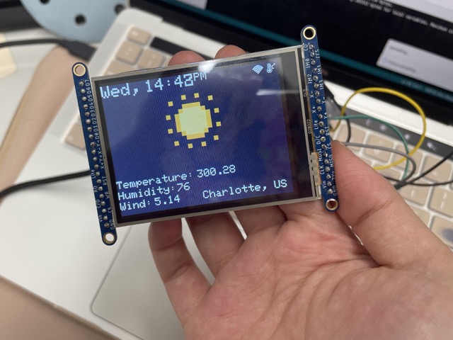
Here is it working:
For the bitmap designs in the right corner, I simply saved the pre-written code from this website :)
Using an MicroSD Card
In order to display specific icons pertaining to the current weather status, I used a micro SD card, given by fellow student Ryan Zhou with the slot on the back of the screen. To begin formatting the sd card, I used a USB insert with the card inside. Adafruit created a project that was similar in nature and had also used openweathermap, so I simply downloaded their .bmp files (labeled accordingly to the icon codes on openweathermap) and moved them to the sd card. After clicking eject, I inserted the sd card into the screen’s slot. Additionally, I connected the Card CS pin to GPIO16 on the ESP32 (though other pins should also work).
In Arduino IDE, under the Adafruit_Imagereader library, I modified parts of the ShieldILI9341 example to test if the screen could display the bitmaps alongside the weather data. I added these lines to ensure that the bitmap associated with the current weather would display:
String icon = myObject["weather"][0]["icon"];
String bmpFileName = "/" + icon + ".bmp"; // constructs the file location


reader.drawBMP(bmpFileName.c_str(), tft, -10, -50); // this function displays the bitmap according to the file, display, x pos. and y pos.
For the timer screen, I also wanted to incorporate some cute bitmaps, so I went onto Pixil Art and began drawing out some cute tomatoes that fit the theme of pomodoro. I exported these as .png files, converted it to 24 bit color (accepted by the ILI9341 driver), and then converted it again to a .bmp file.

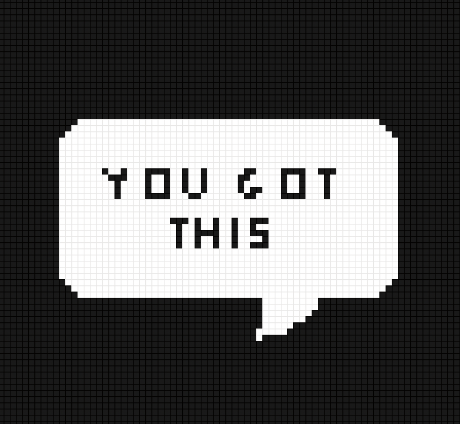
Here’s an example of a pixel art tomato and some encouraging text I drew (with my trackpad lol)
Exploring Touch Features
Because I wanted to have two pages to display on my screen, I needed to figure out how to get the actual touch features to work. I had gotten it to work previously with the Arduino, but I couldn’t figure out the connections on the ESP32. I noticed that the back of the lcd had four main pins for touch:
-
Y+ must be an Analog pin
-
X- must be an Analog pin
-
Y- can be any Digital pin
-
X+ can be any Digital pin
Although there are a bunch of analog/digital pins on the ESP32, I quickly learned that redefining them in the breakouttouchpaint example sketch didn’t enable touch; I tested this with a couple of different pins on the esp to no avail. I originally thought it was an issue with my connections, so I went online to see if anyone had successfully gotten touch to work. I eventually found this forum, which led me to this website and explained how to use the ADC1 pins on the chip. From this, I selected the following pins: A5 for YP and A4 for XM.
Unfortunately, when I uploaded the code, it would only work very sporadically. I asked Dr. Harris for advice, to which he suggested testing the Touchscreen.h library individually. I used the map() function to define a range of values based on the dimensions of the screen (320 x 240) and measured x, y, and z pressures. Here is the code I used:
// Touch screen library with X Y and Z (pressure) readings as well
// as oversampling to avoid 'bouncing'
// This demo code returns raw readings, public domain

#include <stdint.h>
#include "TouchScreen.h"

#define YP A5  // must be an analog pin, use "An" notation!
#define XM A4  // must be an analog pin, use "An" notation!
#define YM 14   // can be a digital pin
#define XP 12  // can be a digital pin

// For better pressure precision, we need to know the resistance
// between X+ and X- Use any multimeter to read it
// For the one we're using, its 300 ohms across the X plate
TouchScreen ts = TouchScreen(XP, YP, XM, YM, 300);

void setup(void) {
  Serial.begin(9600);
  pinMode(2, OUTPUT); // this is the pin for the built-in LED
}

void loop(void) {

  // a point object holds x y and z coordinates
  TSPoint p = ts.getPoint();

  // we have some minimum pressure we consider 'valid'
  // pressure of 0 means no pressing!
  if (p.z < 50) {
    int x_pos = map(p.x, -2500, 600, 0, 240);
     Serial.print("X = "); Serial.print(x_pos);
     int y_pos = map(p.y, -2500, 600, 0, 320);
     Serial.print("\tY = "); Serial.print(p.y);
     Serial.print("\tPressure = "); Serial.println(p.z);
     if (x_pos < 100 && y_pos < 100) {
      digitalWrite(2, HIGH);
     } else {
      digitalWrite(2, LOW);
     }
  }

  //delay(100);
}
Take note of the
map()function here, which recallibrates the screen’s mapping system into its actual dimensions (240 x 320). This makes it easier to locate certain ranges on the screen.
Now that I confirmed the screen itself was taking analog inputs, alongside displaying I could begin designing my ESP32 Wroom PCB!
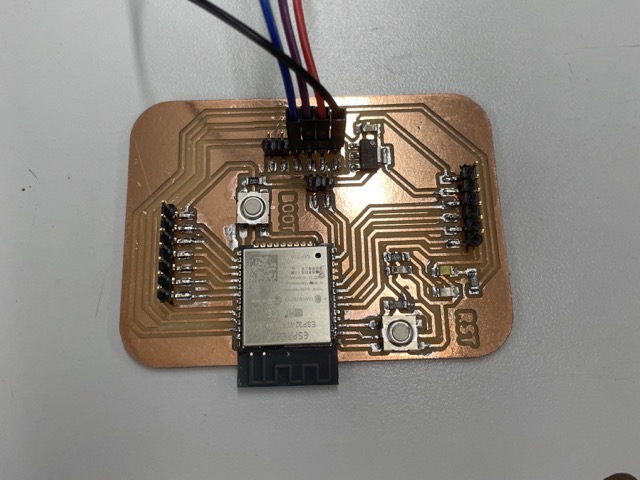
Producing the ESP32 Wroom Board
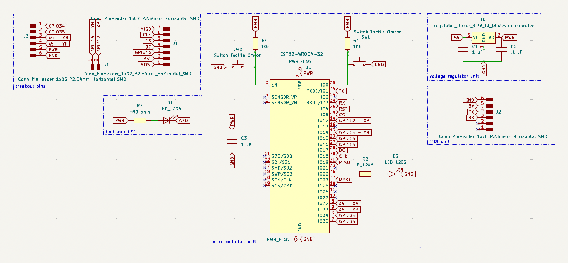
When creating my board, I followed alongside Neil’s example, adding two buttons and pullups for reset and boot. Because I was using an FTDI converter (RX / TX) to program this chip, I also needed to include a 3.3V voltage regulator. Here is how the board turned out:
Routing this board drove me absolute nuts, but after 45 minutes of struggle and squeezing the life out of the android plush in the lab, I came up with this:

For this board, I used the .005” engraving bit, 1/64” flat end mill bit, and 1/32” flat end mill bit. I kept all other settings as standard (refer to Electronics Production for more information).
I soldered the following components on the board, using a smaller iron tip and solder paste for the ESP32 chip.
| Component | Quantity |
|---|---|
| ESP32 Wroom 32 | 1 |
| SMD blue LED | 1 |
| SMD white LED | 1 |
| 6-pin SMT vertical male header | 2 |
| 7-pin SMT vertical male header | 1 |
| 2-pin SMT vertical male header | 1 |
| 499 1206 SMD resistor | 2 |
| 970 nF capacitor (~1uF) | 2 |
| Milled PCB | 1 |
| Tactile push button | 2 |
| 3.3V voltage regulator | 1 |
| 10k ohm resistor | 2 |
| .1 uF capacitor | 1 |
For more information, visit Interface and Application programming.
Crash Course on UART Programming
To begin programming the ESP32 wroom, I bought a FT232RL converter off amazon, which came with a cord and jumpers. Then, following Joaleong’s documentation, who had created a similar board, I learned that the computer needed to recognize two things in order to program the chip:
-
The FTDI converter
-
The ESP32 chip
Following her documentation, she suggested first checking if the computer (Macbook) recognizes the FTDI converter. I opened up terminal and typed the command ioreg -p IOUSB -l -w0 and confirmed the converter was picked up by the computer after seeing FT232RL pop up. Next, I installed an FTDI virtual COM port (VCP) driver, taken from here. I similarly downloaded the Max OS X10.15 and macOS11 version and it seemed to work fine, though you need to move the installer into Applications and give permission from System Preferences before running. After restarting my computer and opening up Arduino IDE, I saw the USB to UART port, called /dev/cu.usbserial-A50285BI.
I made the following connections between the converter and the chip. CTS (clear to send) and RTS (request to send) aren’t necessary in this case:
-
RXD to TX
-
TXD to RX
-
5V to VCC
-
GND to GND
How to Upload a Program
-
Hold down the boot button
-
Upload the program as usual
-
While it is uploading, press the reset button
Here is the final code I used, which integrates features from the sd card and the touchscreen. I also created my own 24 color bitmap drawing to be displayed on the timer screen :>.
// bitmap to byte message on the timer screen

const int study_minutes = 0;
const int short_break_minutes = 5;
const int long_break_minutes = 15;


static const unsigned char PROGMEM image_paint_0_bits[] = {0x0c,0x00,0x0a,0x00,0x0a,0x00,0xbe,0x40,0xff,0xe0,0xff,0xe0,0x7f,0xe0,0x7f,0xe0,0x7f,0xc0,0x7f,0xc0,0x7f,0xc0,0x7f,0x80,0x7f,0x00,0x7c,0x00,0xf8,0x00,0x80,0x00};
static const unsigned char PROGMEM image_paint_1_bits[] = {0x91,0xe4,0x81,0x87,0xbe,0x71,0x24,0x83,0x04,0x88,0x21,0x24,0x82,0x04,0x88,0x21,0xe3,0x82,0xe4,0x88,0x21,0xe0,0x03,0xc7,0x88,0x00,0x00,0x00,0x00,0x00,0x00,0x00,0x00,0x00,0x00,0x00,0x00,0x00,0x00,0x00,0x00,0x7f,0x24,0xe0,0x00,0x00,0x09,0x24,0x80,0x00,0x00,0x09,0xe4,0xe0,0x00,0x00,0x09,0x34,0x20,0x00,0x00,0x09,0x34,0xe0,0x00};
static const unsigned char PROGMEM image_paint_2_bits[] = {0x00,0x00,0x40,0x22,0x00,0x00,0x00,0x00,0x00,0x00,0x00,0x00,0xc3,0x80,0x30,0x00,0x02,0x02,0x50,0x00,0x00,0x02,0x40,0x00,0x00,0x00,0x00,0x00,0x00,0x00,0x00,0x00,0x62,0x00,0x00,0x00,0x00,0x00,0x00,0x00,0x00,0x00,0x00,0x00,0x00,0x10,0x00,0x00,0x00,0x10,0x00,0x00};
static const unsigned char PROGMEM image_paint_3_bits[] = {0x90,0x60};

static const unsigned char PROGMEM image_paint_5_bits[] = {0x80,0xe0,0xb0,0x8c,0x86,0x8e,0x98,0xf0,0xc0};
static const unsigned char PROGMEM image_paint_6_bits[] = {0xe1,0xc0,0xa1,0x40,0xa1,0x40,0xa1,0x40,0xa1,0x40,0xa1,0x40,0xa1,0x40,0xa1,0x40,0xe1,0xc0};

// timer icons


#include <Adafruit_GFX.h>         // Core graphics library
#include <Adafruit_ILI9341.h>     // Hardware-specific library
#include <SdFat.h>                // SD card & FAT filesystem library
#include <Adafruit_SPIFlash.h>    // SPI / QSPI flash library
#include <Adafruit_ImageReader.h> // Image-reading functions

#include <WiFi.h>
#include <HTTPClient.h>
#include <Arduino_JSON.h>

#include <NTPClient.h>
#include <WiFiUdp.h>

#include <TouchScreen.h>

//Touchscreen X+ X- Y+ Y- pins
#define YP A5  // must be an analog pin, use "An" notation!
#define XM A4  // must be an analog pin, use "An" notation!
#define YM 14   // can be a digital pin
#define XP 12   // can be a digital pin

TouchScreen ts = TouchScreen(XP, YP, XM, YM, 300);

String alternative;

String weekDays[7]={"Sun", "Mon", "Tue", "Wed", "Thu", "Fri", "Sat"};
String months[12]={"Jan", "Feb", "Mar", "Apr", "May", "Jun", "Jul", "Aug", "Sep", "Oct", "Nov", "Dec"};
static const unsigned char PROGMEM image_weather_temperature_bits[] = {0x1c,0x00,0x22,0x02,0x2b,0x05,0x2a,0x02,0x2b,0x38,0x2a,0x60,0x2b,0x40,0x2a,0x40,0x2a,0x60,0x49,0x38,0x9c,0x80,0xae,0x80,0xbe,0x80,0x9c,0x80,0x41,0x00,0x3e,0x00};
static const unsigned char PROGMEM image_wifi_full_bits[] = {0x01,0xf0,0x00,0x07,0xfc,0x00,0x1e,0x0f,0x00,0x39,0xf3,0x80,0x77,0xfd,0xc0,0xef,0x1e,0xe0,0x5c,0xe7,0x40,0x3b,0xfb,0x80,0x17,0x1d,0x00,0x0e,0xee,0x00,0x05,0xf4,0x00,0x03,0xb8,0x00,0x01,0x50,0x00,0x00,0xe0,0x00,0x00,0x40,0x00,0x00,0x00,0x00};

// This is calibration data for the raw touch data to the screen coordinates
#define TS_MINX -2300
#define TS_MINY -2600
#define TS_MAXX 400
#define TS_MAXY 500

#define USE_SD_CARD


#if defined(ESP8266)
  #define TFT_CS   5
  #define TFT_DC   17
  #define SD_CS    2
#elif defined(ESP32) && !defined(ARDUINO_ADAFRUIT_FEATHER_ESP32S2)
  #define TFT_CS   5
  #define TFT_DC   17
  #define SD_CS    16

#else // Anything else!
  #define TFT_CS   5
  #define TFT_DC   17
  #define SD_CS    16
#endif

#if defined(USE_SD_CARD)
  SdFat                SD;         // SD card filesystem
  Adafruit_ImageReader reader(SD); // Image-reader object, pass in SD filesys
#else
  // SPI or QSPI flash filesystem (i.e. CIRCUITPY drive)
  #if defined(__SAMD51__) || defined(NRF52840_XXAA)
    Adafruit_FlashTransport_QSPI flashTransport(PIN_QSPI_SCK, PIN_QSPI_CS,
      PIN_QSPI_IO0, PIN_QSPI_IO1, PIN_QSPI_IO2, PIN_QSPI_IO3);
  #else
    #if (SPI_INTERFACES_COUNT == 1)
      Adafruit_FlashTransport_SPI flashTransport(SS, &SPI);
    #else
      Adafruit_FlashTransport_SPI flashTransport(SS1, &SPI1);
    #endif
  #endif
  Adafruit_SPIFlash    flash(&flashTransport);
  FatVolume        filesys;
  Adafruit_ImageReader reader(filesys); // Image-reader, pass in flash filesys
#endif

Adafruit_ILI9341       tft    = Adafruit_ILI9341(TFT_CS, TFT_DC);
Adafruit_Image         img;        // An image loaded into RAM
int32_t                width  = 0, // BMP image dimensions
                       height = 0;

void timer();

const char* ssid = "tigerhome";
const char* password = "yy8701yy";


String openWeatherMapApiKey = "e0f21e445c4ebf1aec3b6ebab38b7261";


String city = "Charlotte";
String countryCode = "US";

// THE DEFAULT TIMER IS SET TO 10 SECONDS FOR TESTING PURPOSES
// For a final application, check the API call limits per hour/minute to avoid getting blocked/banned
unsigned long lastTime = 0;
// Timer set to 10 minutes (600000)
//unsigned long timerDelay = 600000;
// Set timer to 10 seconds (10000)
unsigned long timerDelay = 10000;

String jsonBuffer;


WiFiUDP ntpUDP;
NTPClient timeClient(ntpUDP);


void setup(void) {

  ImageReturnCode stat; // Status from image-reading functions

  Serial.begin(9600);
  while(!Serial)  delay(100);       // Wait for Serial Monitor before continuing

  tft.begin();          // Initialize screen

  // The Adafruit_ImageReader constructor call (above, before setup())
  // accepts an uninitialized SdFat or FatVolume object. This MUST
  // BE INITIALIZED before using any of the image reader functions!
  Serial.print(F("Initializing filesystem..."));
#if defined(USE_SD_CARD)
  // SD card is pretty straightforward, a single call...
  if(!SD.begin(SD_CS, SD_SCK_MHZ(25))) { // ESP32 requires 25 MHz limit
    Serial.println(F("SD begin() failed"));
    for(;;); // Fatal error, do not continue
  }
#else
  // SPI or QSPI flash requires two steps, one to access the bare flash
  // memory itself, then the second to access the filesystem within...
  if(!flash.begin()) {
    Serial.println(F("flash begin() failed"));
    for(;;);
  }
  if(!filesys.begin(&flash)) {
    Serial.println(F("filesys begin() failed"));
    for(;;);
  }
#endif
  Serial.println(F("OK!"));


  // Load full-screen BMP file 'purple.bmp' at position (0,0) (top left).
  // Notice the 'reader' object performs this, with 'tft' as an argument.
  Serial.print(F("Loading weather.bmp to screen..."));
  tft.fillScreen(ILI9341_BLACK);
  //stat = reader.drawBMP("/01d.bmp", tft, 0, 0);
  // (Absolute path isn't necessary on most devices, but something
  // with the ESP32 SD library seems to require it.)
  //reader.printStatus(stat);   // How'd we do?


  delay(2000); // Pause 2 seconds before moving on to loop()
  WiFi.begin(ssid, password);
  timeClient.begin();
  timeClient.setTimeOffset(-14400);
  Serial.println("Connecting");
  while(WiFi.status() != WL_CONNECTED) {
    delay(500);
    Serial.print(".");
  }
  Serial.println("");
  Serial.print("Connected to WiFi network with IP Address: ");
  Serial.println(WiFi.localIP());


}
void loop() {
  TSPoint p = ts.getPoint();
  p.x = map(p.x, TS_MINY, TS_MAXY, 0, 240);
  p.y = map(p.y, TS_MINX, TS_MAXX, 0, 320);


 // if (p.x >= 135 && p.x <= 200 && p.y >=195 && p.y <=330) {
  if (p.x >= 180 && p.x <= 210 && p.y >=-10 && p.y <=80) {

    tft.fillScreen(0);

    reader.drawBMP("/tom.bmp", tft, 0, 0);


    tft.fillRoundRect(44, 37, 55, 29, 4, 0xFFFF);
    tft.drawBitmap(76, 57, image_paint_0_bits, 11, 16, 0xFFFF);
    tft.drawBitmap(51, 45, image_paint_1_bits, 39, 13, 0x0);
    tft.drawBitmap(59, 45, image_paint_2_bits, 31, 13, 0xFFFF);
    tft.drawBitmap(64, 48, image_paint_3_bits, 4, 2, 0x0);
tft.drawCircle(178, 117, 10, 0xFFFF);
tft.drawBitmap(175, 113, image_paint_5_bits, 7, 9, 0xFFFF);
tft.drawCircle(225, 117, 10, 0xFFFF);
tft.drawBitmap(220, 113, image_paint_6_bits, 10, 9, 0xFFFF);


    tft.setCursor(140, 60);

    tft.setTextColor(ILI9341_WHITE);
    tft.drawRoundRect(130, 50, 140, 48, 5, ILI9341_WHITE);
   // tft.println("25:00");
   while(true) {

    TSPoint p = ts.getPoint();
      p.x = map(p.x, TS_MINY, TS_MAXY, 0, 240);
p.y = map(p.y, TS_MINX, TS_MAXX, 0, 320);

  if (p.x >= 120 && p.x <= 165 && p.y >=170 && p.y <=200) {
    timer();

  }

  }

  }


    delay(1000); // Pause 1 sec.
    if ((millis() - lastTime) > timerDelay) {
    // Check WiFi connection status
    if(WiFi.status()== WL_CONNECTED){
      String serverPath = "http://api.openweathermap.org/data/2.5/weather?q=" + city + "," + countryCode + "&APPID=" + openWeatherMapApiKey;

      jsonBuffer = httpGETRequest(serverPath.c_str());
      Serial.println(jsonBuffer);
      JSONVar myObject = JSON.parse(jsonBuffer);

      // JSON.typeof(jsonVar) can be used to get the type of the var
      if (JSON.typeof(myObject) == "undefined") {
        Serial.println("Parsing input failed!");
        return;
      }
      delay(1000);

      tft.setRotation(1);

      String icon = myObject["weather"][0]["icon"];
      String bmpFileName = "/" + icon + ".bmp";

      reader.drawBMP(bmpFileName.c_str(), tft, -10, -50);


      tft.setRotation(1);
      tft.setTextSize(3);
      tft.setTextColor(ILI9341_WHITE);
      tft.setCursor(0, 0);
      timeClient.update();
      String hour = String(timeClient.getHours());
      String minute = String(timeClient.getMinutes());
      String weekDay = weekDays[timeClient.getDay()];
      tft.println(weekDay + ",");
      tft.setCursor(80, 0);
      tft.println(hour + ":" + minute);
      if(hour.toInt() >= 12){
    alternative = "PM";
  }else{
    alternative = "AM";
  }
      tft.setTextSize(2);
      tft.setCursor(170, 0);
      tft.println(alternative);
      tft.drawBitmap(301, 4, image_weather_temperature_bits, 16, 16, 0xFFFF);
      tft.drawBitmap(276, 4, image_wifi_full_bits, 19, 16, 0xFFFF);

      tft.setTextSize(2);
      Serial.print("JSON object = ");
      Serial.println(myObject);
      tft.setCursor(0, 175);
      tft.println("Temperature: ");
      tft.setCursor(150, 175);
      int temp = myObject["main"]["temp"];
       int new_temp = (temp - 273.15)*9/5 + 32;
       tft.println(new_temp);
       tft.setCursor (165, 175);  tft.println("  deg. F");
      Serial.print("Pressure: ");
      Serial.println(myObject["main"]["pressure"]);
      tft.setCursor(0, 195);
      tft.println("Humidity: ");
      tft.setCursor(110, 195);
      tft.println(myObject["main"]["humidity"]);
      tft.setCursor(0, 215);
      tft.println("Wind: ");
      tft.setCursor(65, 215);
      tft.println(myObject["wind"]["speed"]);
      tft.setCursor(155, 215);
      tft.println(city + ", " + countryCode);
   // taken from circuit python :D  weather = json.loads(weather)
     // weather_icon = weather['weather'][0]['icon']
      //self.set_icon("/sd/icons/"+weather_icon+".bmp")
      tft.drawRoundRect(5, 35, 90, 25, 4, ILI9341_WHITE);
      tft.fillRoundRect(5, 35, 90, 25, 4, ILI9341_WHITE);
      tft.setCursor(20, 45);
      tft.setTextSize(1);
      tft.setTextColor(ILI9341_BLACK);
      tft.println("POMO TIME!");


    }
    else {

      tft.setCursor(45, 20);
      tft.println("WiFi Disconnected");
    }
    lastTime = millis();
  }
}


String httpGETRequest(const char* serverName) {
  WiFiClient client;
  HTTPClient http;

  // Your Domain name with URL path or IP address with path
  http.begin(client, serverName);

  // Send HTTP POST request
  int httpResponseCode = http.GET();

  String payload = "{}";

  if (httpResponseCode>0) {
    Serial.print("HTTP Response code: ");
    Serial.println(httpResponseCode);
    payload = http.getString();
  }
  else {
    Serial.print("Error code: ");
    Serial.println(httpResponseCode);
  }
  // Free resources
  http.end();

  return payload;
}

void timer() {


      int seconds = 0;

    int minutes = 25;
    int minutesstudied = 0;
      tft.setCursor(0, 215);
      tft.setTextSize(2);


    tft.println("Total time studied: ");


    // count up and display the timer during study period
    //  if (p.x >= 140 && p.x <= 165 && p.y >=170 && p.y <=190) {


        Serial.println("received!");


        while(minutes>=study_minutes){ // keep counting until we've reached the time limit for a study session


          // print out the timer value in mm:ss format
          while (minutes > 0 || seconds > 0) {

            tft.setTextSize(2);
            tft.fillRoundRect(230, 215, 60, 50, 5, 0x2946);
             tft.setCursor(230, 215);

             tft.println(minutesstudied);
                  tft.setTextSize(4);
            tft.setCursor(140, 60);
            if(minutes<10){  // if minutes is less than 10, we need to print an extra 0 to the display
              tft.println("0");
              tft.setCursor(165, 60);
              tft.println(minutes);

            } else {
            tft.setCursor(140, 60);
            tft.println(minutes);
            }
            tft.setCursor(190, 60);
            tft.println(":");
            if(seconds<10){  // if seconds is less than 10, we need to print an extra 0 to the display
              tft.setCursor(215, 60);
              tft.println("0");
              tft.setCursor(240, 60);
              tft.println(seconds);
            } else {
            tft.setCursor(215, 60);
            tft.println(seconds);
            }
            // wait for one second then increment the second counter
            delay(1000);


            tft.fillRoundRect(130, 50, 140, 48, 5, 0x2946);
            tft.drawRoundRect(130, 50, 140, 48, 5, ILI9341_WHITE);
            seconds--;
            if (seconds < 0) {
            seconds = 59;

          // increment the minute counter after 60 seconds have elapsed

          minutesstudied ++;
          minutes--;


      }


    }
  }

}
It worked!
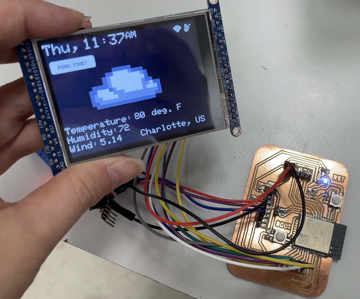
Here is the functional 25 minute timer that displays encouraging messages, a tomato bitmap, and the total time studied:
Assembly
I sanded down the key as it was initially two thick to fit within the joint. Then, I began layering my table:
Afterwards, I installed several strands of programmable neopixels on the lip of the table. I simply soldered wires of three colors (yellow, blue, red) to represent data, ground, and power. I applied hot glue to all soldered areas to prevent the wires from potentially touching each other. Then, to fasten the neopixels down onto the wood, I removed the adhesive backing and firmly pressed it down.
![]()
System Integration + Electronics Management
In terms of electronics management, I knew that system integration would become a big aspect of my project, especially given the crazy amount of wires required between the ESP32 board and the tft lcd.
RP2040 Board Case
First, I 3D-printed a couple of mounts to keep my boards in place: for my main RP2040 tomato board, I created a similar design to Teddy Warner, adding two areas to screw the mount in and an area for the cord to go. This fit pretty well and kept the board secure.

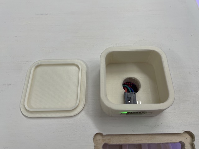
ESP32 Board Case
I also made a similar case for the ESP32 board, using the .step file from KiCad (File>Export>STEP from the PCB editor).

So many wires to manage :,D
Wire Mounts
Next, I designed these simple wire mounts, again with inspiration from Teddy’s design. I printed these with organic supports, which I found were the easiest to remove in this case.
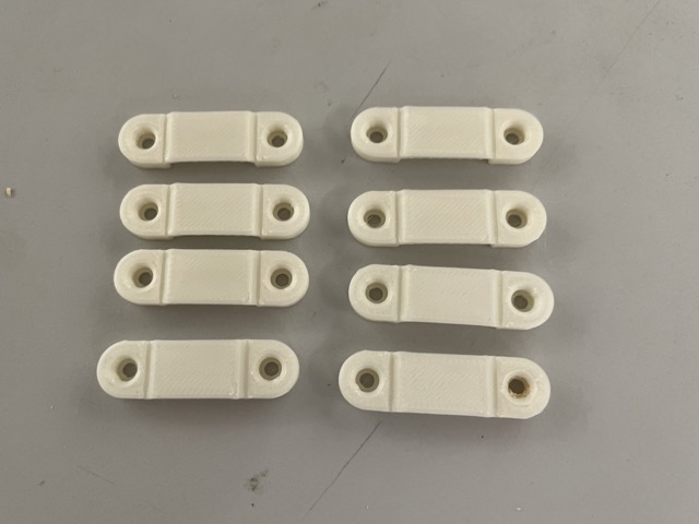
In the future, I would recommend making these a bit larger and thicker. Although they worked pretty well, certain ones ended up being a bit flimsy.
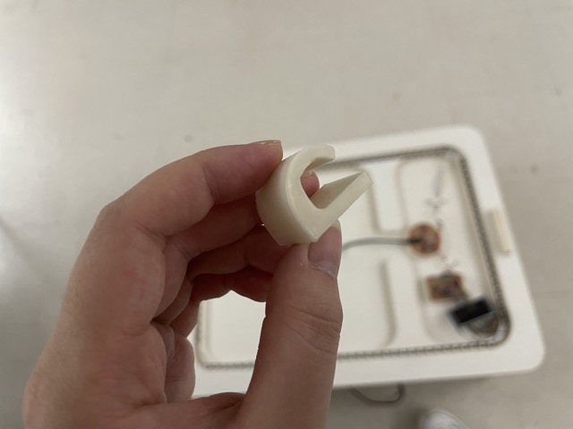
Time of Flight Case
The original supports were a bum to remove, so I printed this case rotated on its side, with organic supports added.
Back Hook
I initially planned on screwing this into the side, but after some re-consideration, I decided to simply fasten it with nitto tape.
For more information, visit 3D printing and scanning.
Installation
First, since I only needed the top layer to be removable, I decided to glue the first three layers together with wood glue. I clamped these layers together and let it dry for a couple of hours:
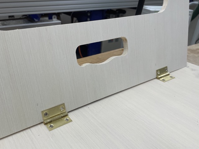
Secondly, I needed to install the hinges onto the bottom of my desk, which would allow the desk to be foldable and easily used on both the floor and on top of an existing table. With the help of Mr. Budzichowski, I first used the table saw to create an angled cut on the legs of my table, before using a power drill and small screws to install the hinges.
Afterward, to integrate all the aforementioned components into one final product, I also used a drill with a phillips head screwdriver and screwed in the cases and the wire mounts. During this time, I unfortunately ripped a trace on my RP2040 board and had to remill it :(.
Here is the final system integration:
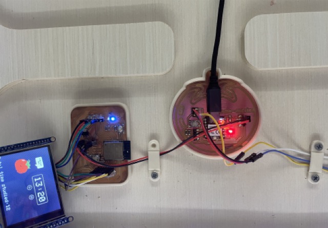
At this point, I didn’t install that last screw holding down the power and ground wires as I would likely still have to re-arrange those later on (as it connects the ESP32 board and xiao board to a common power/ground).
Upon actually layering the desk, I realized that there weren’t enough wood ‘layers’ on the desk, resulting in the electronics/cables getting smushed down. To prevent damaging the electronics, I ended up using the ShopBot to CNC another layer. During the assembly process, I then slightly pushed up the wood slot key to keep the desk together. With a bit of sanding (120 grit) on the inside of the slot, I was able to easily assemble the remainder of my desk!
I ultimately made a small adjustment to the placement of the time of flight: I noticed that the sensor was giving out weird distance values when placed inside the case, so I ended up reorienting it and putting it on the outside.
Customization
For customization, I decided to laser cut and engrave a simple acrylic coaster for the cup holder of my desk. I used 1/8” clear acrylic.
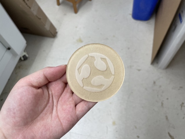
Here is the final coaster installed:
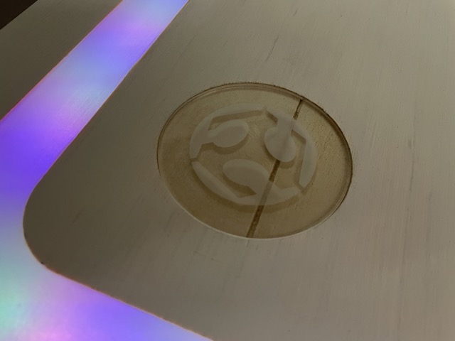
For more information, visit Computer Controlled Cutting.
Files
You can access all project files here.
Acknowledgements
Thank you to Mrs. Morrow, Mr. Budzichowski, Mr. Dubick, Dr. Taylor, Dr. Harris, Mr. Durrett, and Garrett for all of your support and encouragement throughout this process. Your help has been instrumental to this project’s development. Whether staying late in the lab, talking about final presentations, or simply being there to cheer us on, I doubt that any of us would’ve made it without you.
Thank you to my parents for coming out late to pick me up (I still can’t drive lol) and supporting me throughout this entire journey, through both the complaints and successes.
And lastly, thank you to my peers, who have been there every step of the way and experienced all of it with me. Cheers to future engineering projects!!