11. Machine Design and Mechanical Design
This week, our group decided to design, produce, and automate a claw machine! You can access our group site here.
Assignment
group assignment:
-
design a machine that includes mechanism+actuation+automation+application
-
build the mechanical parts and operate it manually
individual assignment:
- document the group project and your individual contribution
Planning
Starting out, after brainstorming some machine ideas, we eventually agreed to follow through with the claw machine. Although the design of the claw machine was intuitive, and there were many existing examples, this project still involved a lot of components. For one, we needed to build a CoreXY system gantry with some form of z-axis built-in for the claw. Additional elements involved a joystick (movement), a 16x2 I2C LCD screen (displays time left), an light up push-button (automates claw), and neopixel strips (decoration).
Research
Individual Contribution
For my individual contribution, I mainly worked on the frame, parts of the gantry, assembling the claw machine, and testing additional electronics.
Claw Machine Frame
For the frame, I started out by sketching the sides of the claw machine, the top and bottom, and the playing area, before adding slots and tabs accordingly. I had measured the wood beforehand and added a .005” offset to the thickness (.47” > .475”), as suggested by Mr. Budzichowski and Mr. Dubick.
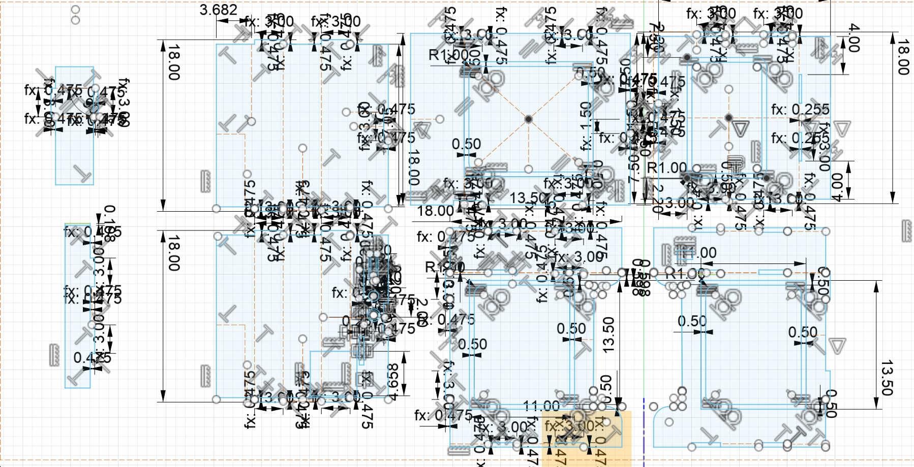
Here is the scaled down version of the sketch.
Here are the parameters I established initially:

After I finished designing the individual components, I extruded the sketches by .475” and used the align tool to assemble them.

Another aspect of this design was to leave enough room for the gantry at the top. After communicating with Connor, I decided that 3.5” was enough to fitthe gantry (~2” tall).

We saved the file as a .dxf and imported it into Aspire to begin generating the toolpaths.
I had to generate a bunch of toolpaths for this design, as there were several profiles and pockets of various depths. I first configured the job setup:

After checking if all vectors were closed, I used the built-in dogbone feature and added them to the design accordingly (I changed the measurement value to the appropriate tool diameter/2). In terms of milling, I followed the our lab’s ShopBot procedures. I first ran an aircut at a 2” z-offset, before homing and running the job again.
The only issue during this process was that the tabs were too shallow and didn’t hold up during the pocket toolpaths. Thankfully, I noticed this issue early on, and with the help of Garrett Nelson, I used the brad nail gun to fasten the wood down again. Later on, Isimply used a chisel and a mallot to remove the sides from the sacrificial board.

After sanding down the edges with 80-100 grit sandpaper, we were able to easily assemble the sides of the claw machine.

For easy access, we decided to just assemble the sides and playing area. Here’s what it looks like:
Acrylic Panels
Next, I needed to install acrylic panels for the sides and back of the claw machine. Because I had created the rectangle pocket during the CNC job, designing the panels was super quick and easy. I cut 2 ~11” x 13.5” pieces of 1/4” acrylic, and a ~13.3” x 12” piece on the laser cutter.
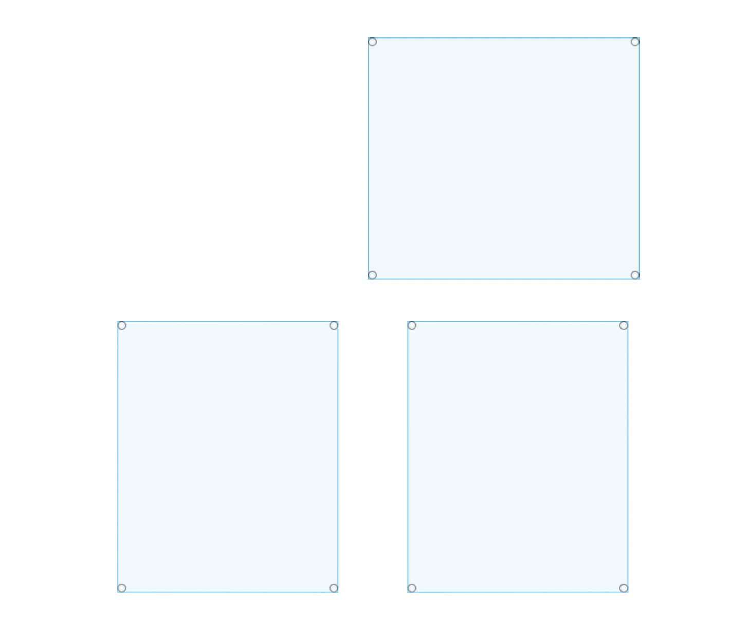
I also added four circles to fit m3 screws.
The first time I ran the job, it didn’t cut through entirely, so I had to run the job again.
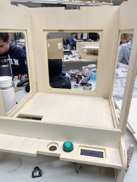
Aligning the panels to the window, Alana and I drilled holes through the sides of the claw machine and installed m3 screws/nuts. Here is what the front looks like after assembling:

Neopixels Installation
For the top of the machine, I also wanted to include a set of neopixels to serve as a decorative piece for the claw machine. I first soldered and tested a strand of neopixels using the following code, which was taken from Dariyah Strachan’s documentation:
// A basic everyday NeoPixel strip test program.

// NEOPIXEL BEST PRACTICES for most reliable operation:
// - Add 1000 uF CAPACITOR between NeoPixel strip's + and - connections.
// - MINIMIZE WIRING LENGTH between microcontroller board and first pixel.
// - NeoPixel strip's DATA-IN should pass through a 300-500 OHM RESISTOR.
// - AVOID connecting NeoPixels on a LIVE CIRCUIT. If you must, ALWAYS
//   connect GROUND (-) first, then +, then data.
// - When using a 3.3V microcontroller with a 5V-powered NeoPixel strip,
//   a LOGIC-LEVEL CONVERTER on the data line is STRONGLY RECOMMENDED.
// (Skipping these may work OK on your workbench but can fail in the field)

#include <Adafruit_NeoPixel.h>
#ifdef __AVR__
 #include <avr/power.h> // Required for 16 MHz Adafruit Trinket
#endif

// Which pin on the Arduino is connected to the NeoPixels?
// On a Trinket or Gemma we suggest changing this to 1:
#define LED_PIN    D3

// How many NeoPixels are attached to the Arduino?
#define LED_COUNT 30

// Declare our NeoPixel strip object:
Adafruit_NeoPixel strip(LED_COUNT, LED_PIN, NEO_GRB + NEO_KHZ800);
// Argument 1 = Number of pixels in NeoPixel strip
// Argument 2 = Arduino pin number (most are valid)
// Argument 3 = Pixel type flags, add together as needed:
//   NEO_KHZ800  800 KHz bitstream (most NeoPixel products w/WS2812 LEDs)
//   NEO_KHZ400  400 KHz (classic 'v1' (not v2) FLORA pixels, WS2811 drivers)
//   NEO_GRB     Pixels are wired for GRB bitstream (most NeoPixel products)
//   NEO_RGB     Pixels are wired for RGB bitstream (v1 FLORA pixels, not v2)
//   NEO_RGBW    Pixels are wired for RGBW bitstream (NeoPixel RGBW products)


// setup() function -- runs once at startup --------------------------------

void setup() {
  // These lines are specifically to support the Adafruit Trinket 5V 16 MHz.
  // Any other board, you can remove this part (but no harm leaving it):
#if defined(__AVR_ATtiny85__) && (F_CPU == 16000000)
  clock_prescale_set(clock_div_1);
#endif
  // END of Trinket-specific code.

  strip.begin();           // INITIALIZE NeoPixel strip object (REQUIRED)
  strip.show();            // Turn OFF all pixels ASAP
  strip.setBrightness(50); // Set BRIGHTNESS to about 1/5 (max = 255)
}


// loop() function -- runs repeatedly as long as board is on ---------------

void loop() {
  // Fill along the length of the strip in various colors...
  colorWipe(strip.Color(255,   0,   0), 50); // Red
  colorWipe(strip.Color(  0, 255,   0), 50); // Green
  colorWipe(strip.Color(  0,   0, 255), 50); // Blue

  // Do a theater marquee effect in various colors...
  theaterChase(strip.Color(127, 127, 127), 50); // White, half brightness
  theaterChase(strip.Color(127,   0,   0), 50); // Red, half brightness
  theaterChase(strip.Color(  0,   0, 127), 50); // Blue, half brightness

  rainbow(10);             // Flowing rainbow cycle along the whole strip
  theaterChaseRainbow(50); // Rainbow-enhanced theaterChase variant
}


// Some functions of our own for creating animated effects -----------------

// Fill strip pixels one after another with a color. Strip is NOT cleared
// first; anything there will be covered pixel by pixel. Pass in color
// (as a single 'packed' 32-bit value, which you can get by calling
// strip.Color(red, green, blue) as shown in the loop() function above),
// and a delay time (in milliseconds) between pixels.
void colorWipe(uint32_t color, int wait) {
  for(int i=0; i<strip.numPixels(); i++) { // For each pixel in strip...
    strip.setPixelColor(i, color);         //  Set pixel's color (in RAM)
    strip.show();                          //  Update strip to match
    delay(wait);                           //  Pause for a moment
  }
}

// Theater-marquee-style chasing lights. Pass in a color (32-bit value,
// a la strip.Color(r,g,b) as mentioned above), and a delay time (in ms)
// between frames.
void theaterChase(uint32_t color, int wait) {
  for(int a=0; a<10; a++) {  // Repeat 10 times...
    for(int b=0; b<3; b++) { //  'b' counts from 0 to 2...
      strip.clear();         //   Set all pixels in RAM to 0 (off)
      // 'c' counts up from 'b' to end of strip in steps of 3...
      for(int c=b; c<strip.numPixels(); c += 3) {
        strip.setPixelColor(c, color); // Set pixel 'c' to value 'color'
      }
      strip.show(); // Update strip with new contents
      delay(wait);  // Pause for a moment
    }
  }
}

// Rainbow cycle along whole strip. Pass delay time (in ms) between frames.
void rainbow(int wait) {
  // Hue of first pixel runs 5 complete loops through the color wheel.
  // Color wheel has a range of 65536 but it's OK if we roll over, so
  // just count from 0 to 5*65536. Adding 256 to firstPixelHue each time
  // means we'll make 5*65536/256 = 1280 passes through this loop:
  for(long firstPixelHue = 0; firstPixelHue < 5*65536; firstPixelHue += 256) {
    // strip.rainbow() can take a single argument (first pixel hue) or
    // optionally a few extras: number of rainbow repetitions (default 1),
    // saturation and value (brightness) (both 0-255, similar to the
    // ColorHSV() function, default 255), and a true/false flag for whether
    // to apply gamma correction to provide 'truer' colors (default true).
    strip.rainbow(firstPixelHue);
    // Above line is equivalent to:
    // strip.rainbow(firstPixelHue, 1, 255, 255, true);
    strip.show(); // Update strip with new contents
    delay(wait);  // Pause for a moment
  }
}

// Rainbow-enhanced theater marquee. Pass delay time (in ms) between frames.
void theaterChaseRainbow(int wait) {
  int firstPixelHue = 0;     // First pixel starts at red (hue 0)
  for(int a=0; a<30; a++) {  // Repeat 30 times...
    for(int b=0; b<3; b++) { //  'b' counts from 0 to 2...
      strip.clear();         //   Set all pixels in RAM to 0 (off)
      // 'c' counts up from 'b' to end of strip in increments of 3...
      for(int c=b; c<strip.numPixels(); c += 3) {
        // hue of pixel 'c' is offset by an amount to make one full
        // revolution of the color wheel (range 65536) along the length
        // of the strip (strip.numPixels() steps):
        int      hue   = firstPixelHue + c * 65536L / strip.numPixels();
        uint32_t color = strip.gamma32(strip.ColorHSV(hue)); // hue -> RGB
        strip.setPixelColor(c, color); // Set pixel 'c' to value 'color'
      }
      strip.show();                // Update strip with new contents
      delay(wait);                 // Pause for a moment
      firstPixelHue += 65536 / 90; // One cycle of color wheel over 90 frames
    }
  }
}
![]()
Seeing that it worked, we readjusted the soldering and wiring to fit within the channel on the top piece.
![]()
Whew! Cheers to 50+ neopixels installed and working!
CoreXY: First Iteration
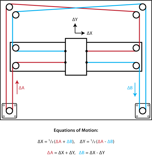
For the gantry, Connor Cruz designed a CoreXY and simulated it in Fusion360. CoreXY uses two main stepper motors and belts to move along the x and y axis. Here is a diagram of the gantry:
Initially, the gantry was designed to have two parallel components for the pulleys and a middle section, but after re-evaluating the structure and the length of the sides (what could be 3D printed vs. what couldn’t), I removed the middle section and modified the sides to join together.
Here was his initial gantry design:

Here is his final gantry design assembled:
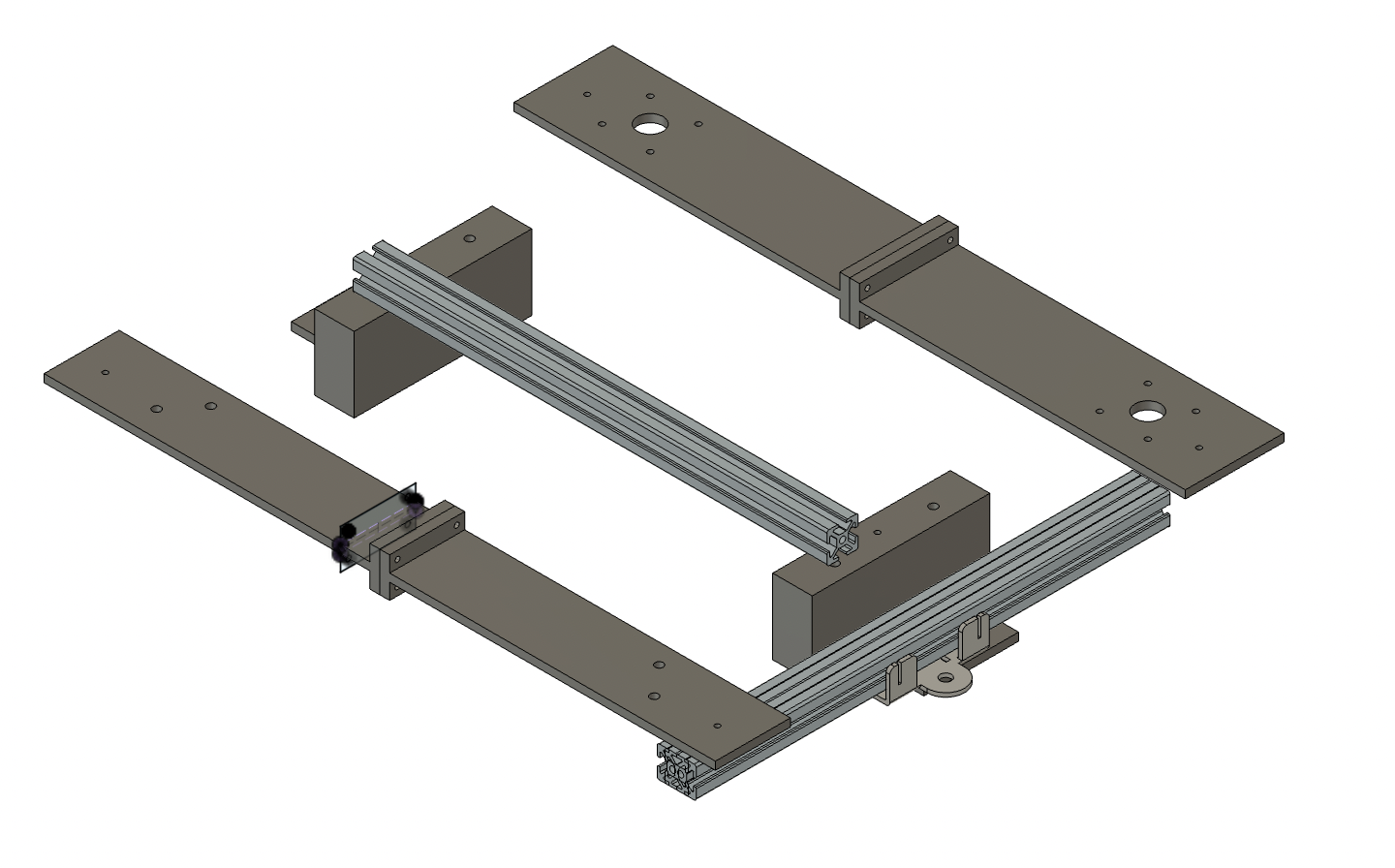
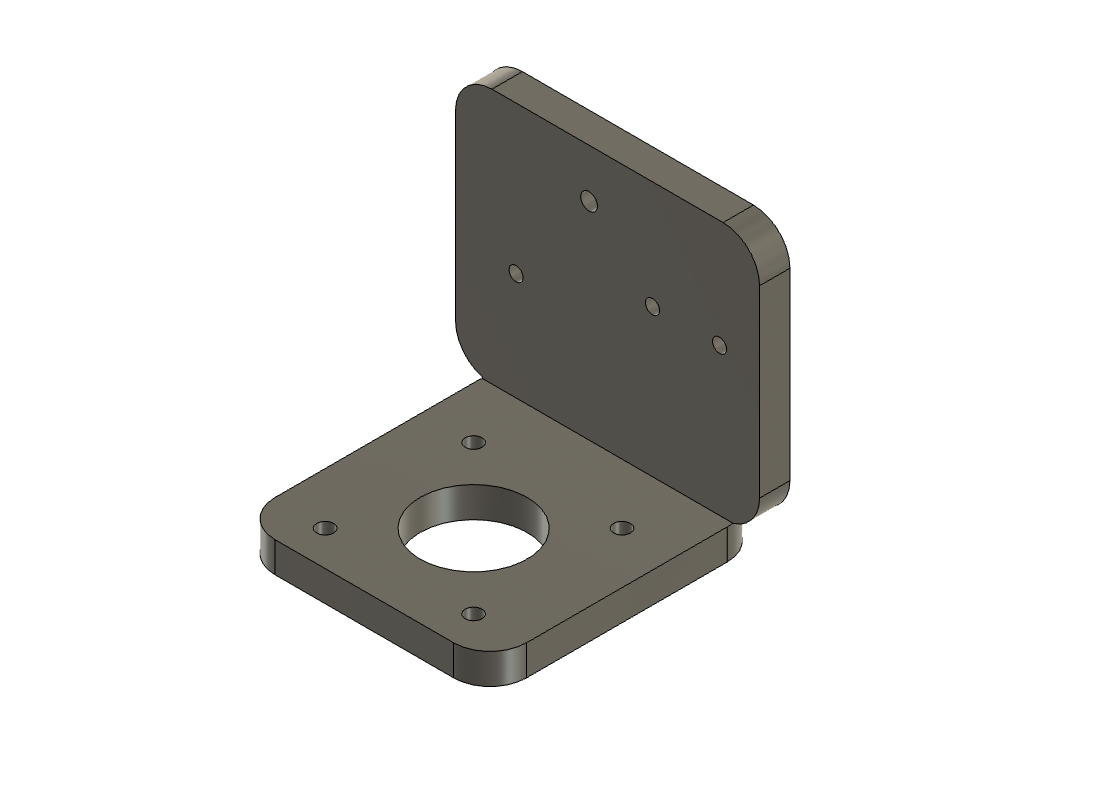
However, we still needed to figure out how to move the claw up and down to grab onto the items. Our inital idea was to use a pulley system with the claw attached, but we weren’t sure if it would work. After meeting up, we settled on using a stepper motor with a lead screw. I began designing a simple connector piece to connect the gantry slider with the stepper motor. I used the [OnShape library] to obtain models for the motor and slider, before projecting the screw holes onto my new sketch and adding a .001” offset. Here is what it looks like:
I imported the 20 mm T-slot to simulate what it would look like attached to the linear axis:

I saved the file as a .STL and brought it into PrusaSlicer to generate the g-code. With Kabir Nawaz’s help, I saved it on my USB and printed it on my PrusaMini.

The only issue was that the models were slightly inaccurate, causing the alignment to be off. Thankfully, the difference wasn’t drastic, so I just used a drill to modify the size. Here is what it looks like fully assembled:
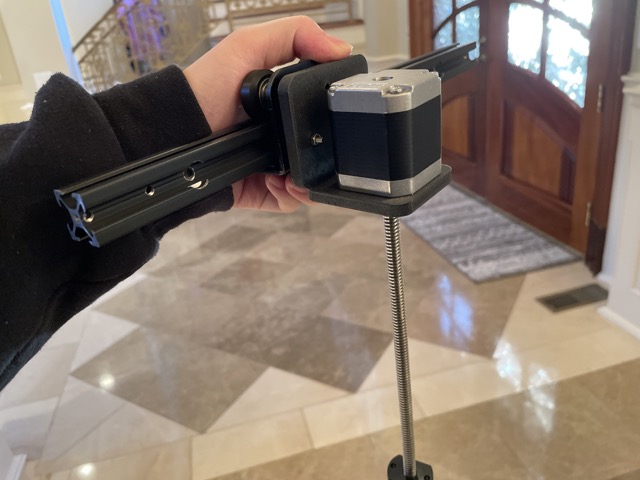
For installation, I used M3 screws of various lengths.
Here is the gantry fully assembled:
Problems with Iteration 1:
-
Though we were able to assemble the 3D printed gantry, we struggled to install the x-axis linear rail onto gantry, which mainly consisted of 3D printed components.
-
When we used the heat inserts, the filament couldn’t fully support it, resulting in the insert falling through.
-
Our next attempt included using adhesives such as hot glue and super glue. While this kept the linear rail stable when moving along the y-axis, it wasn’t sturdy to support the z-axis.
-
Lastly, we tried to fasten the rails onto the gantry using screws and bolt underneath, though this failed to keep the rail still.
-
Thus, we ultimately had to start over from scratch and try a new type of gantry with CoreXY.
CoreXY: Second Iteration
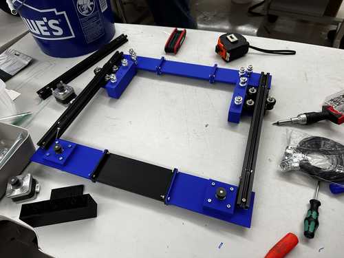
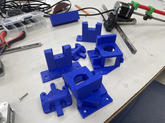
The second iteration followed this video and involved more pre-manufactured components (i.e. different linear rails). We started by downloading this folder and printing the motor bases, the idle supports, and the x-carriage mounts.
To assemble the gantry, we followed the video’s instructions, using M3 screws for the motor/idle supports and 20 mm M5 screws for the pulleys.
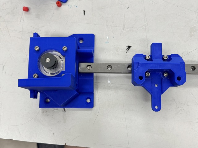
Instead of using the original project’s magnet mount file, which attaches onto the x-axis guide, I designed a z-axis mount, similar to the one in the video, to hold the third motor and a bracket to clip the belt in place. I did not have the original dimensions, since the file was already converted to an .stl, but I was able to get a good estimate. Here is how the design turned out:

I downloaded the linear rail with MGN12H guides model off of OnShape (.step file).
Though there was quite a bit of pressure put on the bracket, this ended up holding the belt securely.
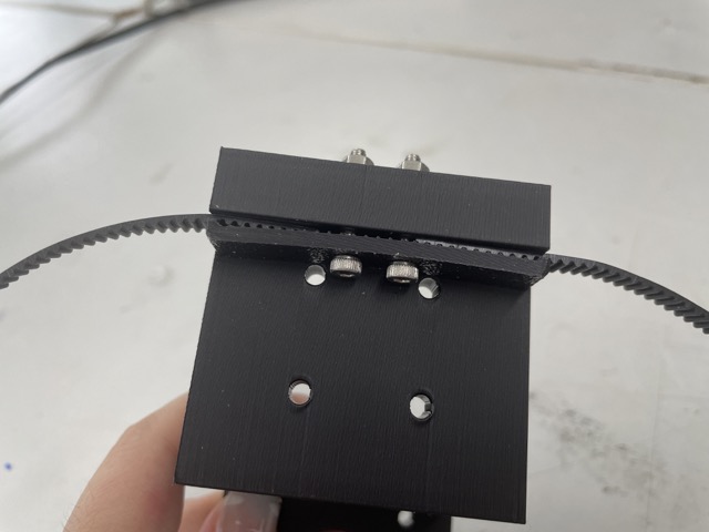
To get the belts in, we simply followed the diagram in the video, cut the end of the belt, and clip it in with the bracket. We ended up having several people pull the belt tight while screwing in the bracket. Here is the second gantry assembled with the z-axis installed:
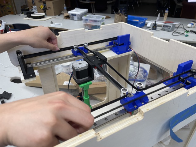
Here is the gantry working by pulling the belts manually:
Reflection
This week both taught and challenged me a lot. Firstly, I enjoyed the team-work aspect, especially as it demonstrated the importance of cooperation and communication. Did things work all the time? No, but it all worked out in the end!
On another note, I feel like this week has prepared me a lot about how to asssemble or design certain aspects of my final project. I’m a lot more comfortable now with the ideation process, and I can finally think through how to do my final project.