10. Output Devices
This week, I began really thinking about what type of board I wanted to use in my final project, and what kinds of outputs I needed to include. I ended up testing out three different outputs, including an i2c lcd, a tft lcd touchscreen, and a neopixel ring. You can access all of my files here.
Assignment
group assignment:
- measure the power consumption of an output device
individual assignment:
- add an output device to a microcontroller board you’ve designed, and program it to do something
Prior Research and Considerations
When I started thinking about my board for this week, I immediately turned to my final project. I knew I wanted to include an LCD of sorts and two types of neopixels, but after neil’s lecture, I was also inspired to include a speaker system! But with so many components in mind and limited time, I wasn’t sure how to execute these ideas. First, I knew that I needed to use a chip that had a lot more pins, as I was looking into using a TFT LCD: instead of producing a board compatible with the 412, as I did in past weeks, I saw that a lot of previous graduates used the ATmega328P. As for the neopixels, I aimed for the 1614, a larger ATtiny with more storage and pins.
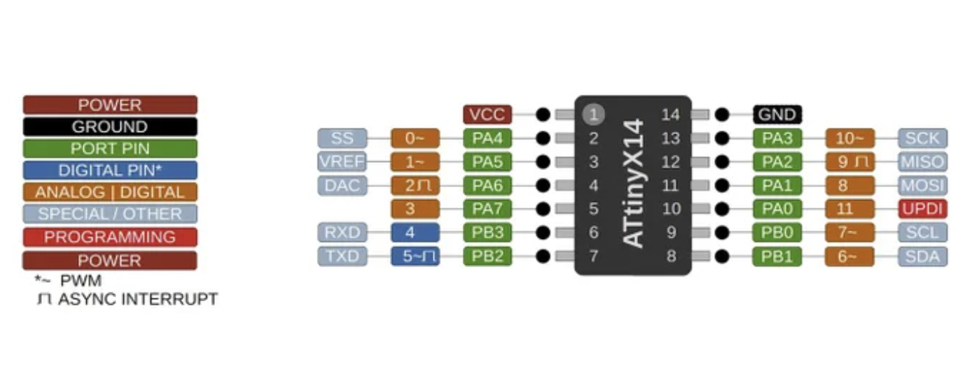
The main difference between the ATtiny412 and the ATtiny1614 is the storage and number of pins. Whereas the 412 has 8 pins, the 1614 has 14.
At this point, I also needed to determine the maximum voltage that these chips can handle, and how much voltage my components required.
Before anything, I wanted to look at individual’s documentation for this week to see if anyone has done anything similar. Fortunately, I found Ginny Foster’s documentation, where she programmed with neopixel strips. From her documentation, I read this Adafruit Guide on Basic Connections, which served as a good reference during my PCB design process. Additionally, from previous experience with neopixels, I knew that neopixels required a 5V power supply, which a ATtiny1614 could handle. Unfortunately, for my other components, I would have to use a different MCU.
I2C LCD
To start off a bit easier, I started with my original final project output, a serial LCD display with an I2C/IIC serial adapter installed already (contains a potentiometer and the I2c pins laid out).
I2C: Inter-integrated Circuit
The inter-integrated circuit is a common synchronous serial communication bus that shares a minimum of two pins, SDA and SCL.
Here is a more detailed description of the pins:
-
SDA: Serial data line is a line for the master and slave to send and receive data at a regular interval
-
SCL: Serial clock line synchronizes all data transfers over the I2C bus.
Connecting the I2C LCD to an Arduino Uno
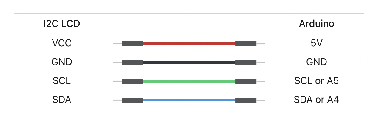
And the prototyping begins! I read this short guide on how to wire the four pins on the lcd. I connected them accordingly:
Then, I downloaded the LiquidCrystal_I2c library and the HD44870 library (known for working well with the 1614). I opened up the example HelloWorld sketch and uploaded it to the Arduino Uno. Initially, because contrast was quite high, all I saw were a line of white blocks. I simply took a phillips head screwdriver and rotated the potentiometer to make the text more visible.
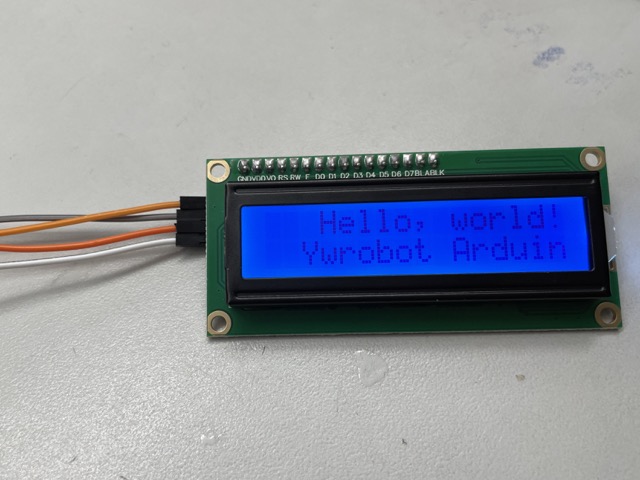
This is what the lcd looks like with low contrast, for example.
Creating a MCU Board for the I2C LCD
To move from the Arduino testing to the QuenTorres, I created a basic schematic in KiCad with an indicator LED, a resistor, header pins for the i2c, a button, and an ATtiny1614.
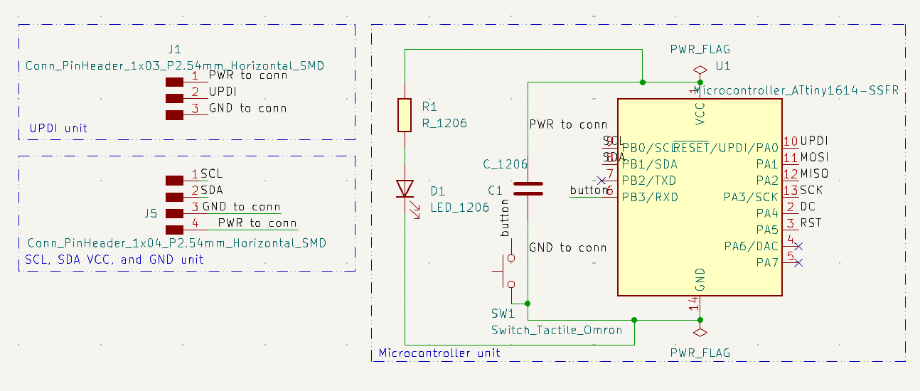
The ATtiny1612 outlines specific pins for SCL and SDA.
I set up the same footprints as during Electronics Design week, swapping out the 412 with a 1614. Additionally, for the constraints and pre-defined route sizes in the PCB layout editor, I also kept it pretty consistent as before.
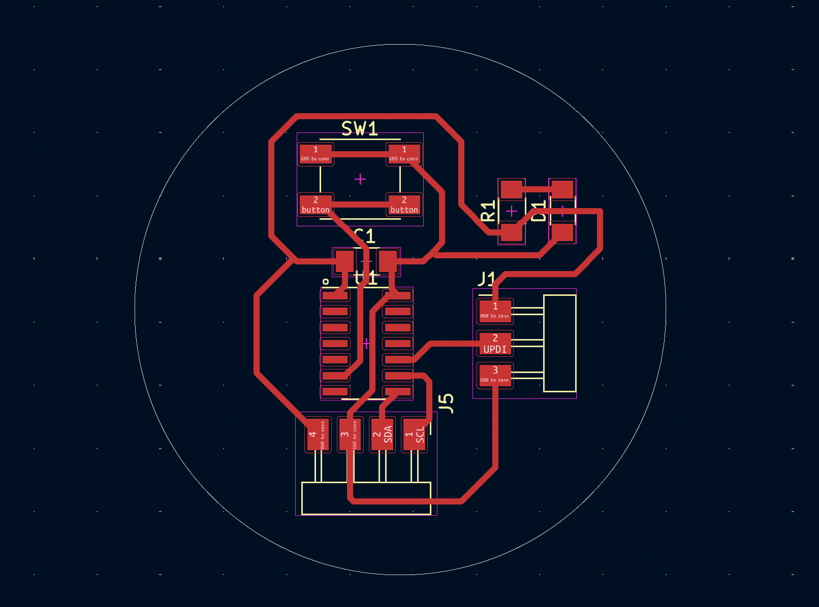
I had no issues while milling or soldering this board. Here was the components I used:
| Component | Quantity |
|---|---|
| ATtiny1614 | 1 |
| 3-pin SMT male header (FTDI) | 1 |
| 4-pin SMT male header (FTDI) | 1 |
| 970 nF capacitor (~1uF) | 1 |
| 499 ohm smd resistor | 1 |
| LED | 1 |
| Tactile switch | 1 |
| Milled PCB | 1 |
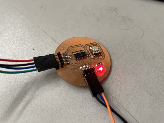
Here is the soldered board with the indicator LED on.
I hooked up the respective pin headers to the lcd with jumper wires and made some quick modifications to the code. Fortunately, it worked!
I also looked into making a simple timer, controlling the button, and using bytes to add custom symbols, which I found from this link. The timer aspect was modified from this project, which my final project was inspired by.
#include <Wire.h>
#include <hd44780.h>                       // main hd44780 header
#include <hd44780ioClass/hd44780_I2Cexp.h> // i2c expander i/o class header

hd44780_I2Cexp lcd; // declare lcd object: auto locate & auto config expander chip
byte customChar[8] = {
  0b00000,
  0b11011,
  0b11111,
  0b01110,
  0b00100,
  0b00000,
  0b00000,
  0b00000
};

// If you wish to use an i/o expander at a specific address, you can specify the
// i2c address and let the library auto configure it. If you don't specify
// the address, or use an address of zero, the library will search for the
// i2c address of the device.
// hd44780_I2Cexp lcd(i2c_address); // specify a specific i2c address
//
// It is also possible to create multiple/seperate lcd objects
// and the library can still automatically locate them.
// Example:
// hd4480_I2Cexp lcd1;
// hd4480_I2Cexp lcd2;
// The individual lcds would be referenced as lcd1 and lcd2
// i.e. lcd1.home() or lcd2.clear()
//
// It is also possible to specify the i2c address
// when declaring the lcd object.
// Example:
// hd44780_I2Cexp lcd1(0x20);
// hd44780_I2Cexp lcd2(0x27);
// This ensures that each each lcd object is assigned to a specific
// lcd device rather than letting the library automatically asign it.

// LCD geometry

int buttonstate = 0 ;

const int LCD_COLS = 16;
const int LCD_ROWS = 2;
const int study_minutes = 5;

void setup()
{
int status;

  // initialize LCD with number of columns and rows:
  // hd44780 returns a status from begin() that can be used
  // to determine if initalization failed.
  // the actual status codes are defined in <hd44780.h>
  // See the values RV_XXXX
  //
  // looking at the return status from begin() is optional
  // it is being done here to provide feedback should there be an issue
  //
  // note:
  //  begin() will automatically turn on the backlight
  //
  status = lcd.begin(16, 2);

  pinMode(4, INPUT);
  lcd.print("Hello, World! :>");
  lcd.setCursor(0, 1);
  lcd.createChar(0, customChar);
  lcd.home();
}

int seconds = 0;
int minutes = 0;
int count = 0;
void loop() {

  buttonstate = digitalRead(4);

  if (buttonstate == LOW) {
    lcd.print("study time!");
    lcd.write(0);

    delay(1000);

    seconds = 0;
    minutes = 0;

    // count up and display the timer during study period
    while(minutes<study_minutes){ // keep counting until we've reached the amount for a study session
      seconds = 0;
      // print out the timer value in mm:ss format
      while(seconds<60){
        lcd.setCursor(0, 1);
        if(minutes<10){  // if minutes is less than 10, we need to print an extra 0 to the display
          lcd.print("0");
        }
        lcd.print(minutes);
        lcd.print(":");
        if(seconds<10){  // if seconds is less than 10, we need to print an extra 0 to the display
          lcd.print("0");
        }
        lcd.print(seconds);
        // wait for one second then increment the second counter
        delay(1000);
        seconds++;
      }
      // increment the minute counter after 60 seconds have elapsed
      minutes++;

    }


  } else {
    lcd.clear();
  }

}
Here is what it looks like working!
TFT LCD Touch Screen
For one of my selected outputs in my final project, I wanted to use a TFT LCD. Specifically, I obtained the 2.8” TFT LCD 320x240 SPI serial with an ILI9341 driver. The datasheet for ILI9341 drivers can be found here.
SPI: Serial Peripheral Interface
Serial peripheral interface enables and facilitates short-distance communication between a microcontroller and other perpheral integrated circuits (ICs). For my assignment, I will be using this to create a synchronous communication between my ATtiny1614 and the LCD screen.
Here are the pins it involves:
-
SCK: Serial Clock controls the timing in communication between any two devices; ranges between 0 and 5 volts
-
MISO: Master Input Slave Output allows the LCD in this case to send signals back to the master, the microcontroller
-
MOSI: Master Output Slave Input allows the master microcontroller to send signals back to the slave, the LCD
-
SS: Slave select consists of other pins to use when you want to control several devices
-
DC: Data / Command
-
RST: Reset
Connecting the TFT LCD to an Arduino Uno
To begin wiring and programming this screen, I followed along with this video, which explains the basics of SPI and how to wire the screen to the Arduino Uno. He particularly mentions the risk of frying the board with the 5V power supply, suggesting that users implement a voltage divider, but after looking through the product information some more, I found that the model I was using was compatible. Then, following essentially the same schematic, I used jumper wires to directly connect the Arduino Uno to the screen. There were only two changes I made during this process: 1) I excluded the recommended resistors, and 2) adivsed by Mr. Durrett, we created a solder bridge on the J1 pad to interrupt the 3.3 V regulator.
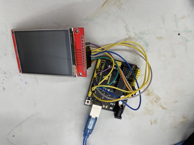
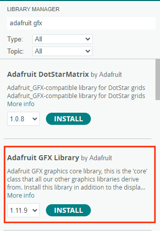
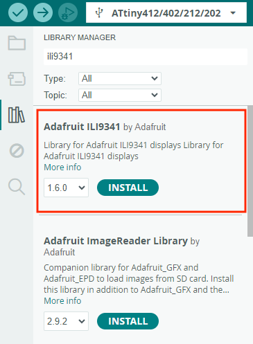
Ensuring these connections were in tact (the screen would remain blank otherwise), I downloaded the Adafruit GFX library and Adafruit ILI9341 library under library manager in Arduino IDE.
Under the adafruit ILI9341 example codes, I opened up the graphicstest, which would run through a series of texts and designs on the screen. Unlike the adafruit version, this lcd doesn’t automatically define the RESET pin in the code, so I added one more line under the initialization of the other pins with:
#define TFT_RST 8
and added TFT_RST into the corresponding function. Here is what the first couple of lines look like:
// For the Adafruit shield, these are the default.
#define TFT_DC 9
#define TFT_CS 10
#define TFT_RST 8

// Use hardware SPI (on Uno, #13, #12, #11) and the above for CS/DC
Adafruit_ILI9341 tft = Adafruit_ILI9341(TFT_CS, TFT_DC, TFT_RST);
Once I checked the wiring and the pin configuration in the code, I uploaded it to my Arduino Uno.
Creating a MCU Board for the TFT LCD
Seeing as the graphics test worked fine on this LCD, I decided to begin designing the custom board. I didn’t want to get involved with the touchscreen quite yet, but still needed to test its capabilities, so I made a slight modification to my plans and used the ATtiny1614 (I convened with Mr. Durrett beforehand to discuss whether the ATtiny would work). I again opened up KiCad and started a new schematic where I pulled in two 1x03 (1 for UPDI and another for VCC and GND for the lcd) conn pin headers and one 1x06 (remaining pins).
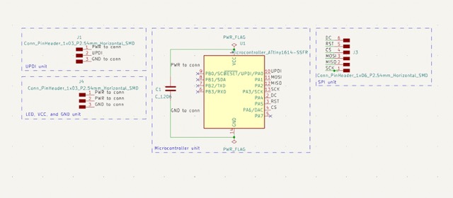
The footprints consisted of C_1206, various size pinheaders, and the SOIC-14_3.9x8.66mm_P1.27 mm chip. When I finished routing and running the DRC, I plotted and saved the design as a Gerber.
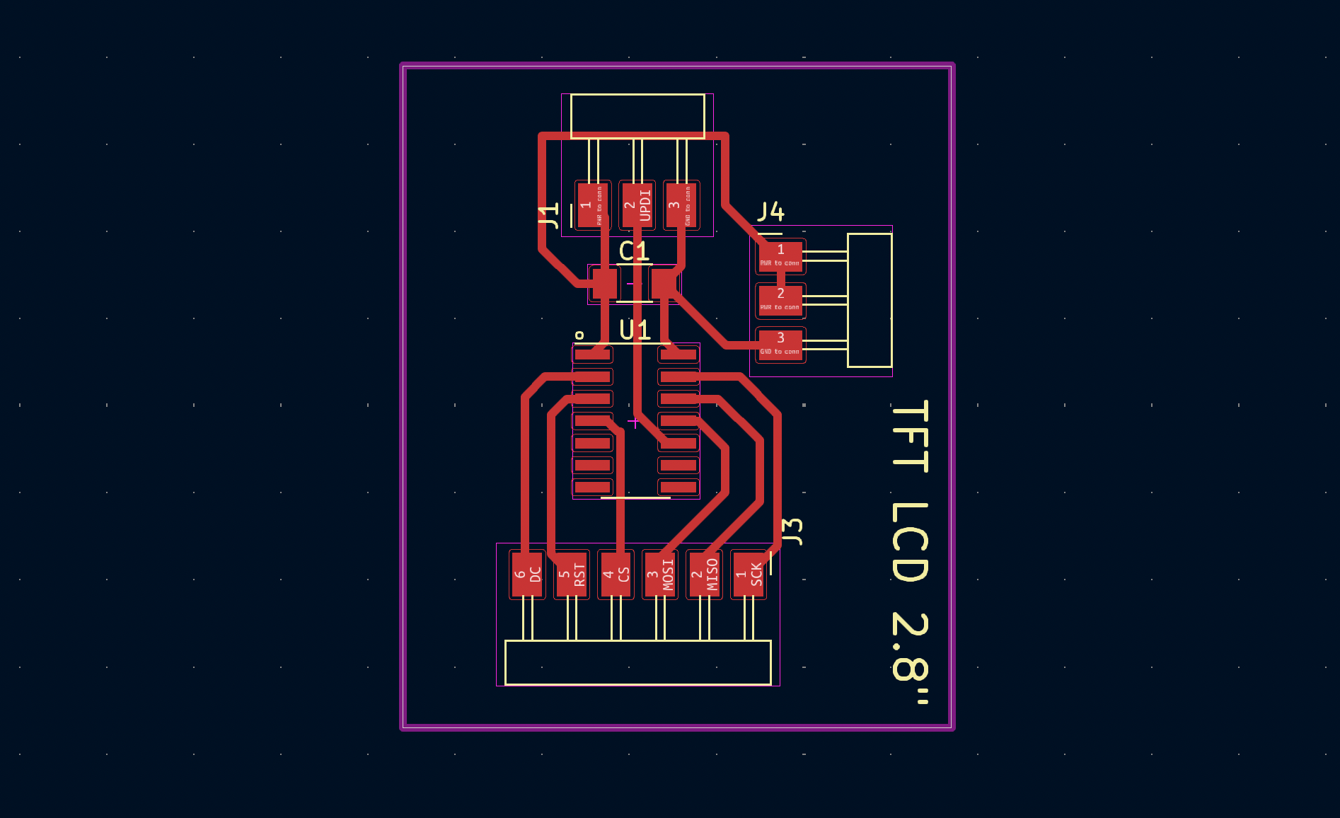
Here is the schematic in the PCB layout editor.
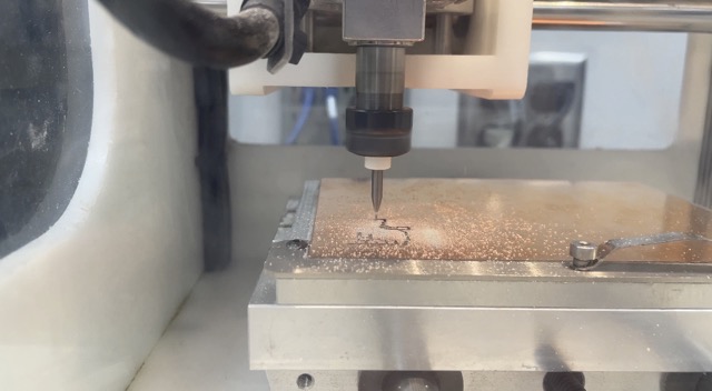
This job required a 1/64” and a 1/32” flat end mill bit. Additional information regarding the PCB milling process can be found in my Electronics Production documentation.
| Component | Quantity |
|---|---|
| ATtiny1614 | 1 |
| 3-pin SMT male header (FTDI) | 2 |
| 6-pin SMT male header (FTDI) | 1 |
| 970 nF capacitor (~1uF) | 1 |
| Milled PCB | 1 |
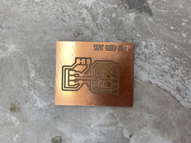
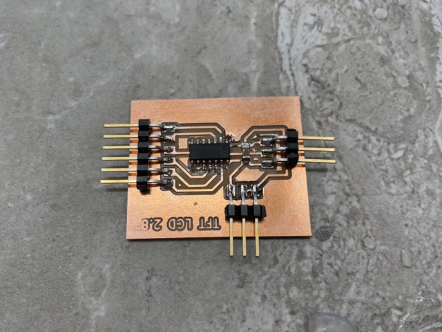
PCB before and after
After connecting the nine pins on the newly milled PCB to the tft lcd, and the three pins for UPDI, GND, and VCC, I selected ATtiny1614 as the chip under the MegaTinycore library.
Unfortunately, although the program compiled and was seemingly sent to the lcd, there was no indication of the graphics test running. The screen wasn’t necessarily blank either; rather, it exhibited a constant flickering state.
In general, I found this board difficult to navigate, and a lot of the previous documentation with the same model didn’t encounter similar issues or use similar microcontrollers. In an effort to be more time effective, I set this aside and began working on the neopixel ring.
Neopixels
Because I have worked with strand neopixels before, I understood the basics of how to wire a ring. I cut, stripped, and soldereed three wires to connect to the 5V, GND, and the DATA-IN pin. All I had to do was connect these to the corresponding pins on the charlie-plexing board I had made the previous week, and define the data-in on my code.
To test, I ran Garrett Nelson’s rainbow ring program that he created during his Embedded programming week.
Here is the code for reference:
//https://github.com/adafruit/Adafruit_NeoPixel/blob/master/examples/strandtest/strandtest.ino
//and
//https://create.arduino.cc/projecthub/robocircuits/neopixel-tutorial-1ccfb9
// NeoPixel Ring simple sketch (c) 2013 Shae Erisson
// Released under the GPLv3 license to match the rest of the
// Adafruit NeoPixel library
// Rainbow from https://codebender.cc/sketch:80438#Neopixel%20Rainbow.ino

#include <tinyNeoPixel.h>
// NeoPixel Ring simple sketch (c) 2013 Shae Erisson
// Released under the GPLv3 license to match the rest of the
// Adafruit NeoPixel library
// modified: sgn, March 2022


// Which pin on the Arduino is connected to the NeoPixels?
#define PIN        4 // Garrett Attiny Neopixel Board

// How many NeoPixels are attached to the Arduino?
#define NUMPIXELS 24 // this was changed to 24 because the ring has 24 neopixels

// When setting up the NeoPixel library, we tell it how many pixels,
// and which pin to use to send signals. Note that for older NeoPixel
// strips you might need to change the third parameter -- see the
// strandtest example for more information on possible values.
tinyNeoPixel pixels(NUMPIXELS, PIN, NEO_GRB + NEO_KHZ800);

#define DELAYVAL 500 // Time (in milliseconds) to pause between pixels

void setup() {
  pixels.begin(); // INITIALIZE NeoPixel strip object (REQUIRED)
  pixels.setBrightness(85); // about 1/3 brightness
  pixels.clear();
}

void loop() {

  rainbow(30);
  delay (20);

}


void rainbow(uint8_t wait) {
  uint16_t i, j;

  for(j=0; j<256; j++) {
    for(i=0; i < pixels.numPixels(); i++) {
      // pixels.setPixelColor(0, pixels.Color(0, 150, 0));
      pixels.setPixelColor(i, Wheel((i*1+j) & 255));
    }
    pixels.show();
    delay(wait);

  }
}

//input a value 0 to 255 to get a color value
// the colors are transitions, r - g - g - back to r
uint32_t Wheel(byte WheelPos) {
  if (WheelPos < 85) {
    return pixels.Color(WheelPos * 3, 255 - WheelPos * 3, 0);
  }
  else if(WheelPos < 170){
    WheelPos -= 85;
    return pixels.Color(255 - WheelPos * 3, 0, WheelPos * 3);
  }
  else {
    WheelPos -= 170;
    return pixels.Color(0, WheelPos * 3, 255 - WheelPos * 3);
  }
}
Group Assignment
For this week’s group assignment, Ryan Zhou and I determined the power consumption of his selected output, a servo motor. You can find our full documentation here.
Individual Contribution
The work was evenly distributed, as both of us measured the voltage/current coming out of the servo, as well as documented.
Reflection
Even though I had heard that Outputs was easier among the weeks, I definitely struggled a lot over these last few days. Particularly, the hardest thing was trying to figure out the tft lcd, as few people had used that model in their final projects. Another challenge that came with using this lcd was time management: I felt more stressed in terms of how to allocate my time, and I ended up spending a lot on the touch screen. In the future, I’ll be sure to be more proactive in my research, so the week will not have so many unexpected outcomes.
Other than that, I wanted to emphasize that I enjoy the freedoms in each week. The extent of creativity that a student has in their work is fully contingent on their own goals, but that also means there are a ton of ways to complete the week’s assignment. Personally, although I “completed” the assignment, I still didn’t feel really satisfied with anything I did. However, in terms of what I did accomplish, I feel like I still learned a decent amount of information about how to interface outputs, specifically the difference between i2c and spi. To say the least, I’m looking forward to inputs week, where I can tackle the tft lcd again!