4. Computer controlled cutting
This week I explored computer controlled cutting through an individual and group project. Computer controlled cutting involves tools that move to a numerically defined location and cuts out a previously specified design. You can access all files here.
Assignment
group assignment:
- characterize your lasercutter’s focus, power, speed, rate,
- kerf, joint clearance and types
individual assignment:
- cut something on the vinyl cutter
- design, lasercut, and document a parametric construction kit, accounting for the laser cutter kerf, which can be assembled in multiple ways,
- for extra credit, include elements that aren’t flat
Vinyl Cutting
For my sticker, I wanted to do something related to miffy because it is one of my favorite characters! I found this cute image that involved 4-5 different colors:

Here is the image of miffy I selected. You can find it here.
Tracing a Bitmap in CorelDraw
Whereas I usually just use the tracing feature in Silhouette studio, I wanted to try something new this time. I followed Adam Stone’s documentation and his approach in CorelDraw, creating a traced bitmap.
Note: a traced bitmap creates a group of vector lines from an original (raster) image!
Selecting the image, I tested out Bitmaps > outline trace > detailed logo, and it worked surprisingly well!
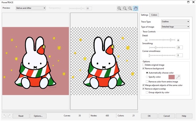
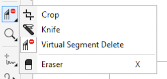
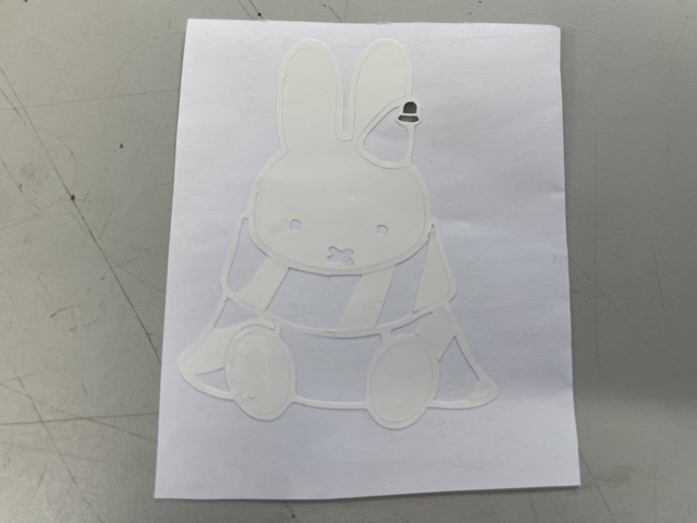
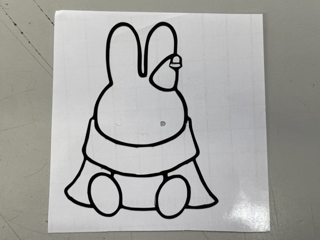
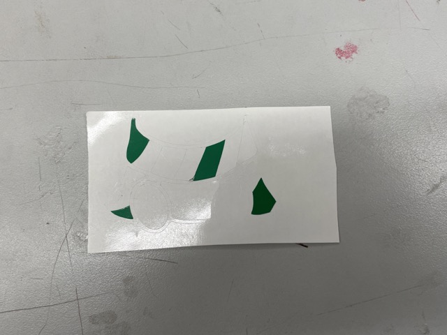
Besides creating the trace bitmap, I wanted to make some minor adjustments to the design itself, particularly with the surrounding gold stars (snowflakes?). To rearrange and delete them, I first ungrouped the components in the bitmap and used the virtual segment delete tool, found in the toolbar. This allows me to easily delete certain segments or components.
For reference, this is what my bitmap looked like before and after making these adjustments:


Before and after of traced ‘mif-map’
Now it looks much cleaner and organized! Time to get started with the vinyl cutter!
Silhouette Studio
I initially exported my CorelDraw file as a .SVG, intending to import it into Silhouette Studio through the import to library feature. However, when I entered the software, it didn’t allow me to import that file type, presenting the message:
File Type Not Supported
Confused, I asked my teacher and previous Fab Academy student, Mr. Durrett, for which files were compatible with Silhouette Studio. He recommended that I use .DXF, a type of vector file.
When I tried that, I successfully imported my bitmap into Silhouette Studio!
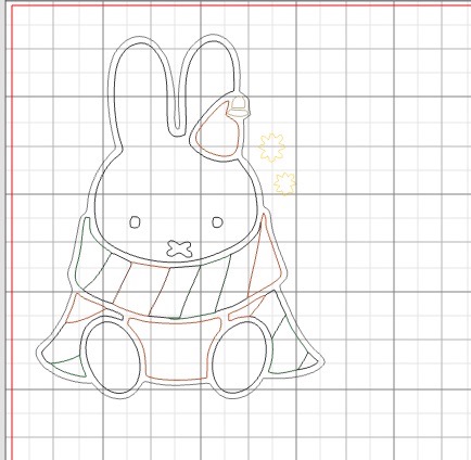
Here is what the sticker looks like in Silhouette studio; when I immported the DXF, it was already fully traced, so there was no need to trace it again.
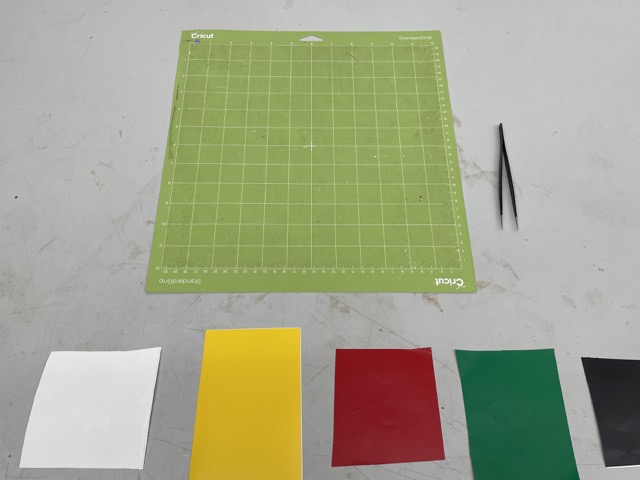
Vinyl cutting materials, including five different colors of vinyl, tweezers, and an adhesive cutting mat
I placed the first vinyl on the cut math and pressed send on the screen to start cutting.
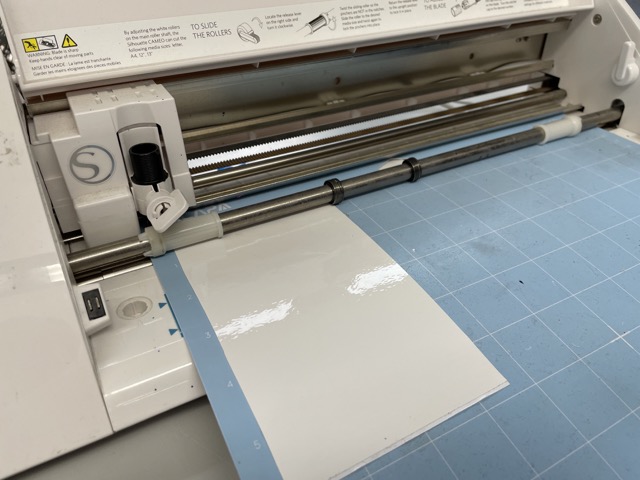
Vinyl cutting in progress
Weeding
The next part of sticker was to weed: weeding refers to removing unwanted or unnecessary parts of a sticker with tweezers. During his recitation, Neil advised students to weed along the plane, rather than perpendicular (pulling up), so I tried to apply this method while removing excess parts of the different layers.
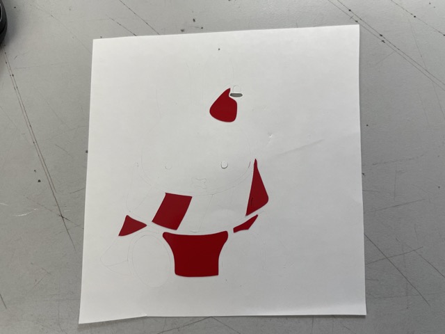
Here’s what the different components looked like after weeding. I noticed that the backing had also been cut during the process, indicating that the cutting strength was likely too high.
All I had to do now was layer them. I used transluscent transfer tape to move the different vinyl stickers from the adhesive map onto a collective sheet. For convenience, I tried to layer it all on the white sticker component. This was a relatively tedious process, as I couldn’t see through the tape entirely. Fortunately, with tweezers and patience, I was still able to successfully layer my stickers (although they are a little bit offset..)
![]()
Here is what my final layered vinyl sticker looks like before transferring.
Per tradition, students got to transfer their stickers over to the window; I used a scraper to flatten a piece of transfer tape over the entire sticker, moving it over to the bottom of the window.
![]()
Here is the sticker on the window with the transfer tape.
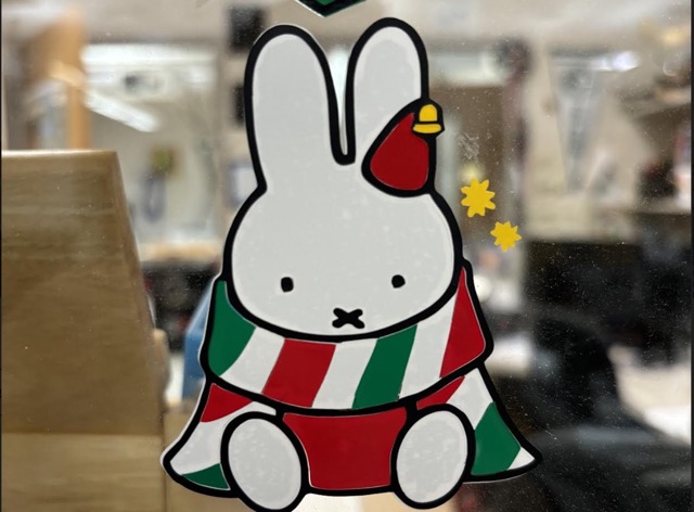
And tada! Here is what my final sticker looks like!
Making a Parametric Construction Kit
The next part of this week’s assignment was to design a parametric kit using parametric design. Parametric design can be very useful with CAD because it allows users to change all values corresponding to a variable, rather than individually making adjustments.
Before designing, I used a pair of calipers to measure the thickness of my cardboard. I would need this later on when designing the width of the slots/tabs.
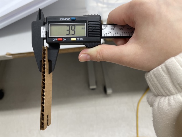
Here is an image of the thickness dimensions for a sheet of cardboard. Although the calipers display mm as the unit, I ended up using inches.
Laser Cutting Workflow
-
Open the file in CorelDRAW
-
Select the entire design and set the width to hairline if you plan to do a vector job (for rastering, keep the original width)
-
Before printing, turn on the ventilation (exhaust) and the power button
-
Save your file as a .CDR
-
Go to file and click
print -
Click “Preferences”
-
Set the correct workspace size
-
Adjust the settings for the material
-
Click
OKandApply -
Press print to send it over to the laser cutter
-
Carefully lift up the lid and place a sheet of material inside the laser cutter
-
Manually focus the laser cutter using the manual focus tool; use the
jogfeature to adjust the distance -
Select the project to print (use the joystick to select)
-
Once selected, press
Go -
Once the laser cutter is finished, open up the lid and take out the box
First Iteration
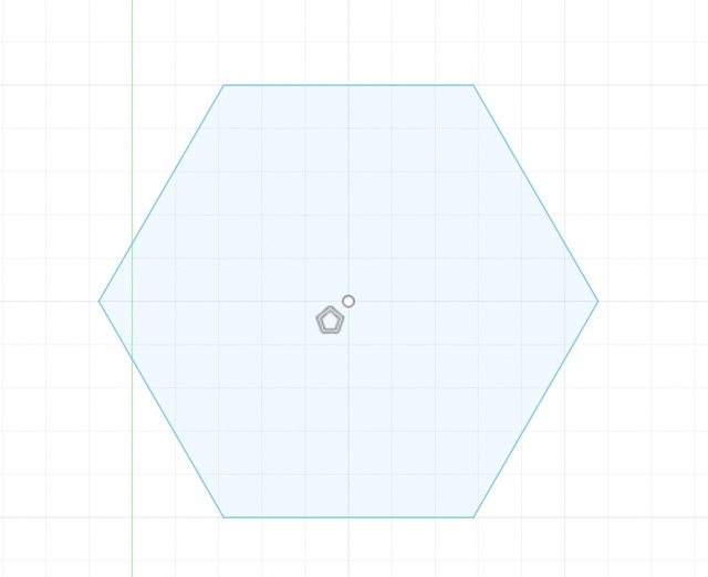
To start out in Fusion 360, I drew an arbitrary circumscribed polygon on the XZ plane.
Before adding dimensions, I set up my parameters. Referencing Adam Stone and Griffin Orsinger’s documentation, I hit the ‘s’ key and typed in parameters to open up the parameters dialogue box. I defined the units as inches, and I began creating variables such as kerf, tablength, tabwidth, sidelength, circle, etc. For the most part, I picked smaller values (i.e. 2 inches per side) for my kit.
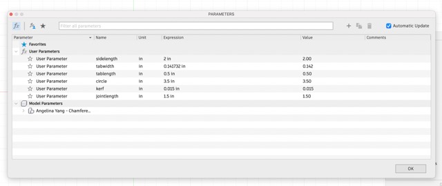
Here are my parameters. I ended up deleting some of them, such as the chamfers because I used fillets instead.
Then, to use my parameters, I used the dimension tool and typed in the name of my parameter.
Fusion360 calculates any expression you put in as well, so you can insert several parameters into one dimension.
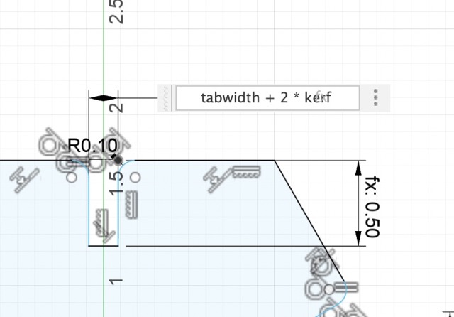
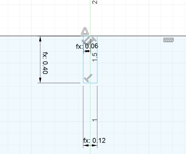
This is what one of my dimensions look like; for reference, my kerf parameter only accounts for one side of the cardboard, so I had to multiply it by 2 and add it to the tabwidth (cardboard thickness).
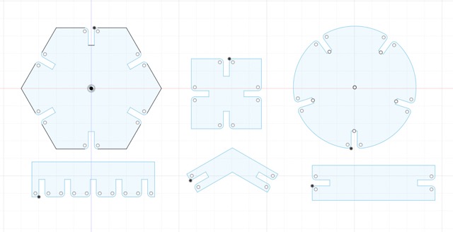
I created a slot at the midpoint of each side, before using the circular pattern feature to quickly replicate it around a center point.
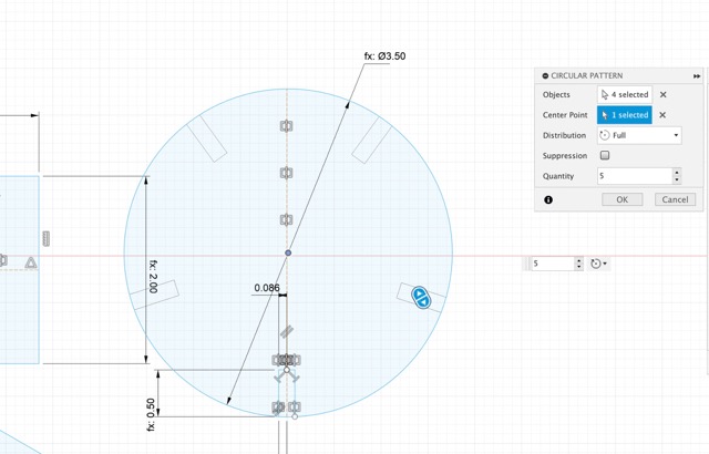
Repeating this process of sketching, applying parameters, and using the circular/rectangular pattern feature, I created three main components and three connector components.
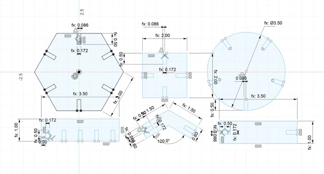
Here’s what the parametric design looked like after applying all parameters.
I applied a .1 in. fillet on the interior of the parametric kit. This ensures that the components connect rather easily without damaging or bending the carboard.
After my design was complete in Fusion 360, I exported it as a .DXF file and brought it into CorelDraw. Here, I noticed that the imported version had completely resized my design, making it significantly bigger. After troubleshooting for a little while, I asked Adam Stone if he had encountered a similar issue, to which he suggested individually resizing each component. I complied, using the parallel dimension tool to check that it corresponds with the original Fusion file. Thankfully, it worked!
Lastly, I established the settings for the laser cutter. I selected print>print preferences and edited the settings. Because this was just a cut with no engraving, I chose vector for the job type. Then, I adjusted the following settings for cardboard: 25% speed, 100% power, 15% frequency.
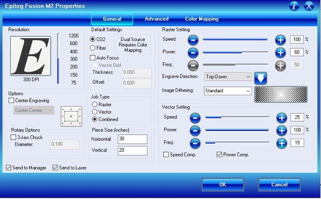
I hit ok followed by Apply to confirm these changes and sent the file to the Epilog laser cutter. I used the jog and focus commands to manually focus the laser cutter, before I ran the job.
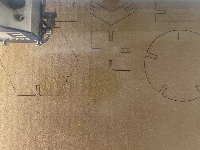
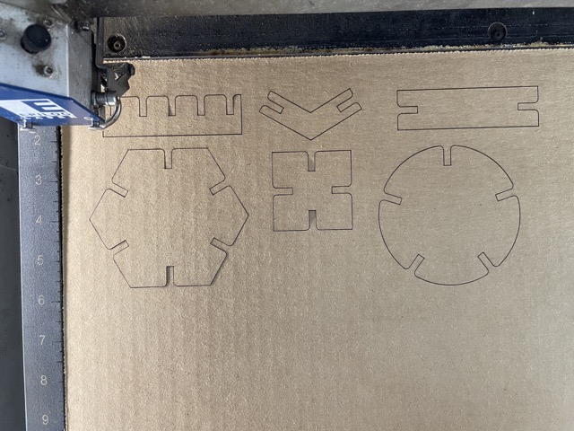
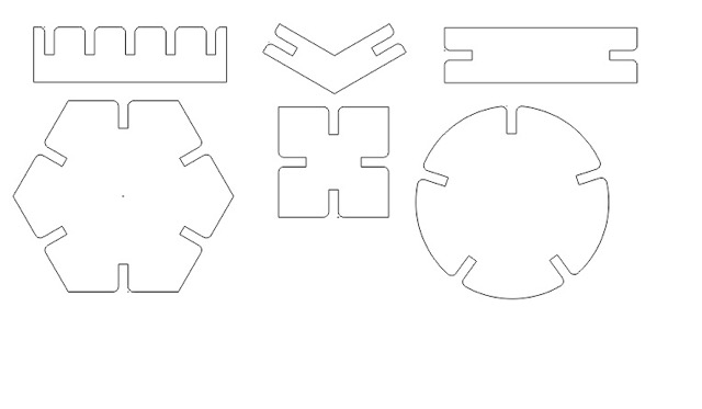
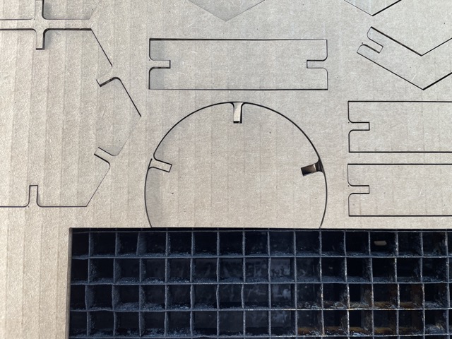
Here is what the components looked like in the laser cutter.
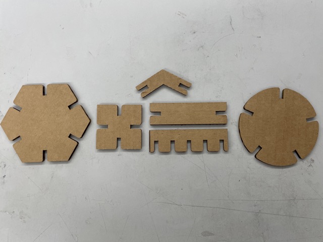
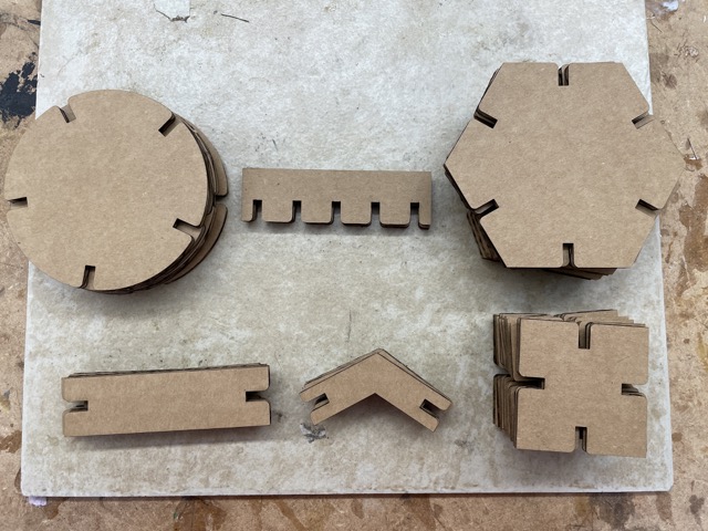
Here are all of the pieces laid out.
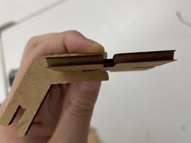
After removing these pieces from the cardboard, I immediately noticed that they were too loose when fit together. This meant that my slot width value was too large, so I took this into account while designing the next iteration.
Second Iteration
During the second iteration, I revisited my previous process, trying to find a potential flaw in my calculations. It was here that I realized that I accidentally added the kerf to the thickness of the cardboard, rather than subtract it. To make these changes, I changed elements in my parameters tab; specifically, I renamed tabwidth as thickness for clarity purposes, and I created a new parameter, thickness - 2 * kerf.
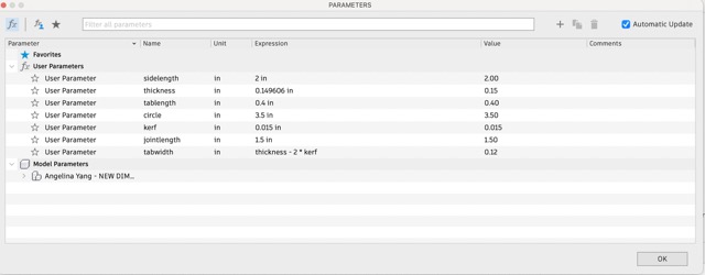
Here are my updated parameters.
Here is what changed specifically in my design.
Third Iteration
When I laser cut these components, they were now a bit too tight. I adjusted my tabwidth once again, and cut it on the laser cutter. This time, I wanted to see what would happen if I disregarded the kerf as a whole (.15 mm slots).
Now the slots fit well with each other!
I cut a few more sets of the components in CorelDraw and similarly cut those.
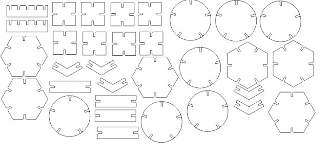
Here is the full file in CorelDraw.
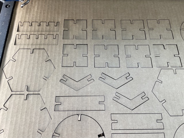
There weren’t any major issues while laser cutting, except a formatting mistake that led to the cut-off of some of the components.
The inevitable fallen soldier..
The first thing I created with my new components was a pair of glasses.
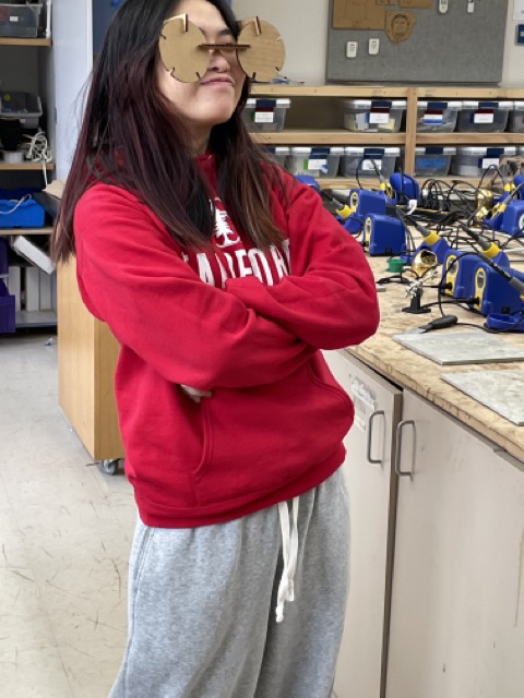
Here’s what I look like with the glasses on!
Fellow Fab Academy student Dariyah Strachan also designed this ant with the remaining pieces, which used the semi-circle from earlier.
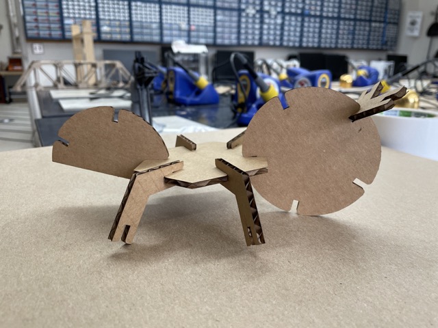
Here’s the finished cardboard ant.
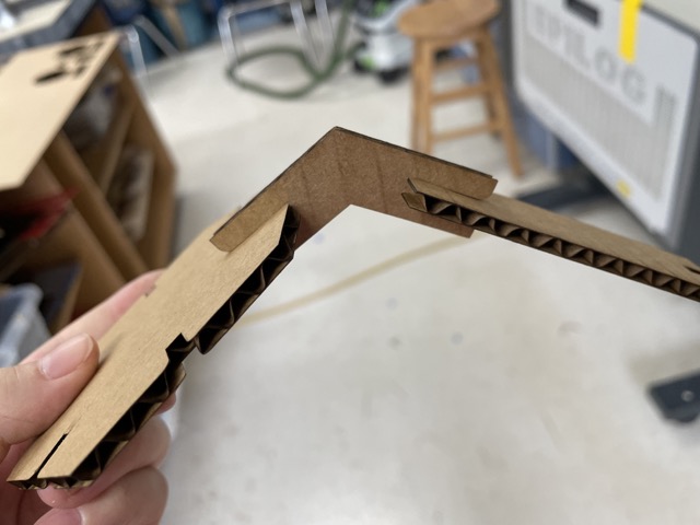
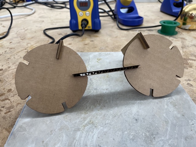
Lastly, I took some inspiration from Griffin Orsinger’s parametric construction kit and decided to use the remaining portion of my pieces to make a structure.
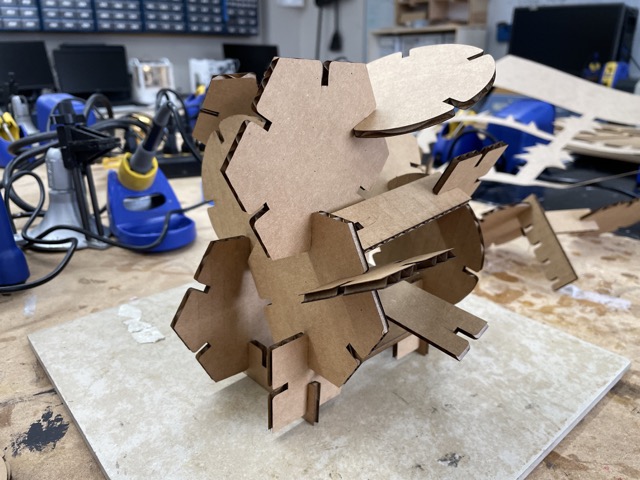
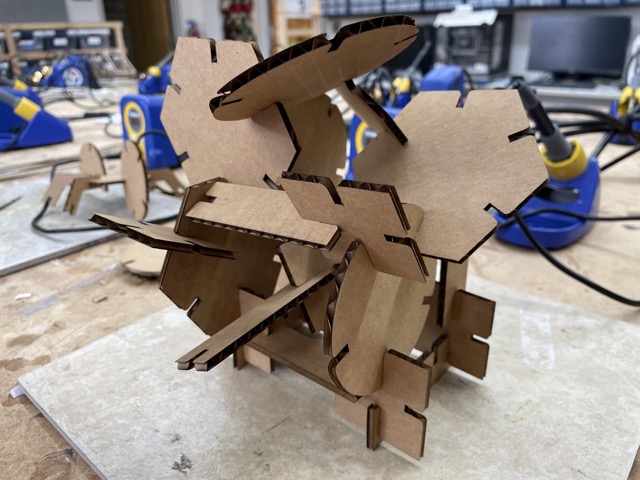
Here is my final parametric construction kit structure.
Group Project
For this group assignment, Richard, Alana, and I characterized our lasercutter’s focus, power, speed, rate, kerf, and joint clearance. We did this by testing different increments in power, speed, and frequency, measuring kerf, and experimenting with various focus settings. Afterwards, I learned a lot about how kerf affects the resulting dimensions of a material, as well as the relationship between other settings. In the future, I will take these into account while laser cutting.
You can find our full documentation here.
Individual Contribution
In terms of my individual contribution, I defined the key terms (kerf, power, frequency, speed, etc.) to help conceptualize the assignment before we began testing; then, I also designed and completed the joint clearance testing (I specifically designed the different slots in Fusion360). Lastly, I, alongside Richard, planned and designed our frequency, power, and speed test sheet; we used Elaine Liu, William Zhou, and Vincent Zhou’s documentation as a reference. All three of us documented in a shared doc, noting the procedure, trends, and errors that occurred.
Week 3 Reflection
This week was the most streamlined and easy-paced week out of the three so far, mainly because I had previous experience in laser cutting and vinyl cutting. I really enjoyed making the vinyl sticker, as well as the parametric construction kit because they shared a more artistic aspect. Additionally, from an academic standpoint, I learned a lot about the laser cutter in general–specifically the role of kerf in designing and the different purposes of the settings. I’m excited for future group assignments!