Week 3 - Computer controlled cutting
Vinyl Cutter
The first thing I did with this week was work on the vinyl cutter. To use the vinyl cutter, we use sillhouette studio in order to design and easily cut what we designed. Mr. Dubick tasked us with creating a multi-colored sticker, a tradition we have in our lab. This is the design I chose for my sticker
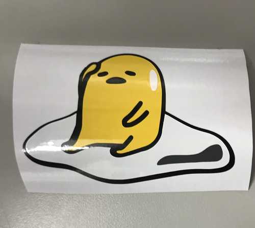
 This is Gudetama the lazy egg, a Japanese character
The process for making a sticker was fairly simple, all you do was use the trace feature within silhouette studio and gradually turn up the threshold as you go up in layers. This is an image of what the image looked like after it was traced
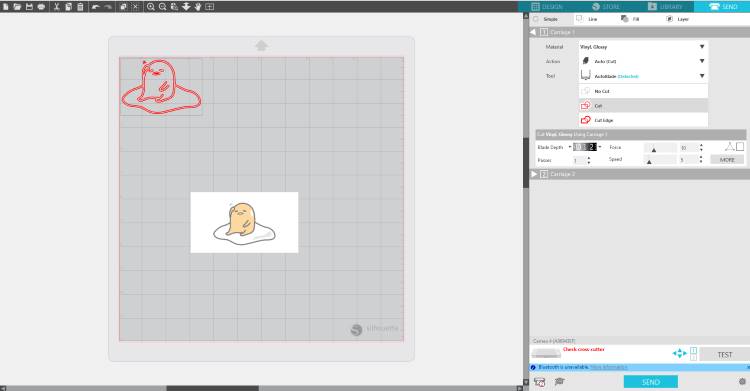
In order to cut the sticker, you select which type of vinyl you are using to get accurate settings in order to not cut too deep, or too shallow. I went between the "vinyl glossy" and the "vinyl matte" options, because those were the closest to what I needed. If desired though, you are able to change the speeds, and depth, in which you cut your stickers on the vinyl cutter, I did not change any of the parameters, because in the past theu had all worked well for me. If your design cuts into the paper, past the vinyl, it is too deep, and it is also essential to make sure your blade is sharp, to ensure clean cuts. When you are setting up the machine, you need to take your piece of vinyl on the cut mat, then I recommend you use a squeegee to adhere it to the mat better. Once you have the cut mat loaded with the vinyl, you line up the cut mat with the line on the vinyl cutter, then once that his lined up, you press the load cut mat option on the vinyl cutter, and once the cut mat is loaded, you can cut your design, which was what I did after my design was totally traced.
I then weeded out all my different layers, but came into the complication of just missing a portion of white vinyl for the mouth. I placed everything together without the white mouth piece to see wheather or not it would be worth cutting another piece of vinyl.
 The sticker without the final piece of the mouth
I came back later to recut the mouth piece because the sticker felt empty without it. I recut the small white portion, and my sticker was finished!
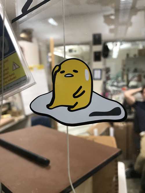 Final sticker design
Complications with vinyl cutting
I only encountered 2 problems when I was vinyl cutting. The first and least important was I accidentally grabbed the wrong type of vinyl, heat transfer, and not the sticky kind. This was easily fixed by just recutting on what I needed to cut on, which had a paper backing. The next issue I had was the vinyl not sticking to the cut mat. I just used the squeegees we had in order to press it down firmly upon the cut mat.
Laser cutting
The laser cutting process was very simple the order of steps goes as follows:
- Place material to cut into the bed of the machine
- Slightly lower the bed using the manual bed control button
- Move the head of the laser to where your material is
- Select autofocus when the head is over the material
- Upload your design to Corel Draw on the PC connected to the laser cutter
- Change the lines you want to cut to hairline
- Press 'Ctrl+P'to cut your design
- Click "OK"
- Change material settings in the Epilog software
- Move your image to where you want it to cut
- Click "print"
- Press the play button on the cutter Keep in mind this is for the large Epilog laser cutter in our lab
After the cut is finished
- Check to see if the parts have been fully cut out, if that is what you designed them to do
- If the parts have not been fully cut, re-run the job without moving the original piece of cardboard
These steps were easy to follow, and there were no issues that I encountered with the laser cutter this week. The main thing to worry about is that there were times when the camera was down on the laser cutter, making it impossible to know where your cut would end up.
Laser cutting my parametric construction kit
The process I went through with creating my construction kit took me 3 itterations. The first itteration I tried to create snap joints and small slots in various shapes of cardboard. Here is what the design looked like in fusion:
When I cut this design out, I had an issue with fitting the pins into the slots. This didn't work out. Here is what this looked like when all the parts were cut out
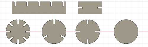
The next itteration I decided to try was creating the slot fit with chamfer design. I initially began this process in cuttle, but there was an issue here, as I couldn't get the Boolean subtract to work the way I wanted it to. I moved the design into fusion again, remade my parameters such as kerf, carboard thickness, and slot depth. Designing with parameters was very helpful, as I didn't need to keep track of the values of each portion I had to design.
 design of this itteration of my project
I cut this out, but after I cut the design out, I realized that the cardboard thickness parameter was incorrect, I had it at about 0.16, but it needed to be 0.125. The slots didn't fit together completely which was a shame, but I knew better what I was going to do for the next itteration.
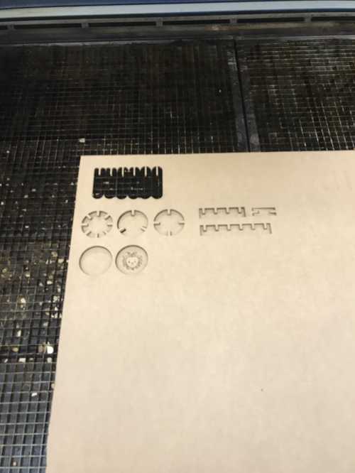 Cut out version of this design
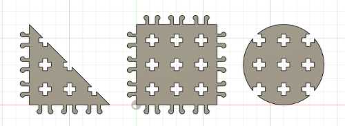
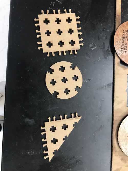
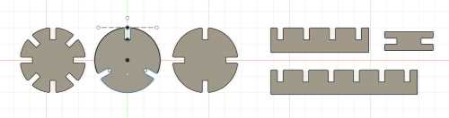
The next itteration I made was the same shapes as the first design, except I had to redesign it, because I had messed up how I created the slots in the first itteration. The way I made it easier to change in the future was using a circular pattern tool AFTER I extruded the shape. This allowed for me to control how the shapes patterned, and made them easier to alter in the future if I wanted different sizes or notch amounts. This is the final design in fusion and the final cut out of these pieces
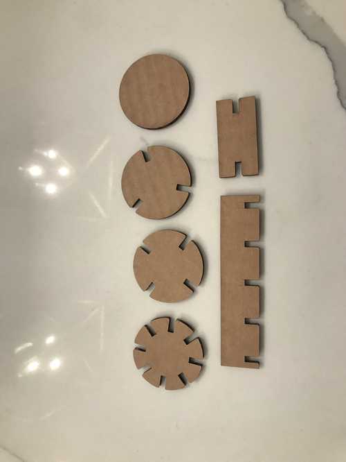
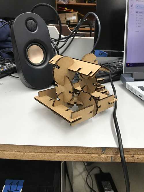 A little house I built!
These pieces worked much better than the other ones, as the slot depth was actually correct this time.
Parametric design process
The process I used to learn parametric design was orginally taught to be my Teddy Warner, and since I learned about this process, it has been how I designed each of my 3d designs since. parametric modeling is a great way to keep track of your dimensions, as well as to change them in the future. When I designed the wheels for my final project, this was very important, as there were many different values that I had to keep track of. I didn't even know the exact dimensions I was using anymore by the end of the design process, but I could easily check in the parameters menu of fusion. The way to get to new parameters is in the modify dropdown menu, then go to change parameters, and click + user parameter to create new parameters to use. Using parameters in a build is easy, when you are dimensioning something just type the name of the parameter you want to use, and the names of the parameters should autofill. Then if you go into your parameters menu again and modify the value of the parameter you used, then you will have changed the dimensions of the actual object. To create my construction kit, the first two itterations weren't designed in a way to where I could change dimensions of the parts and still have it be the same part. The final itteration did, and I learned my lesson from the first one by using the cut tool in fusion to fill out the notches.
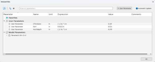
The parameter menu for my construction kit
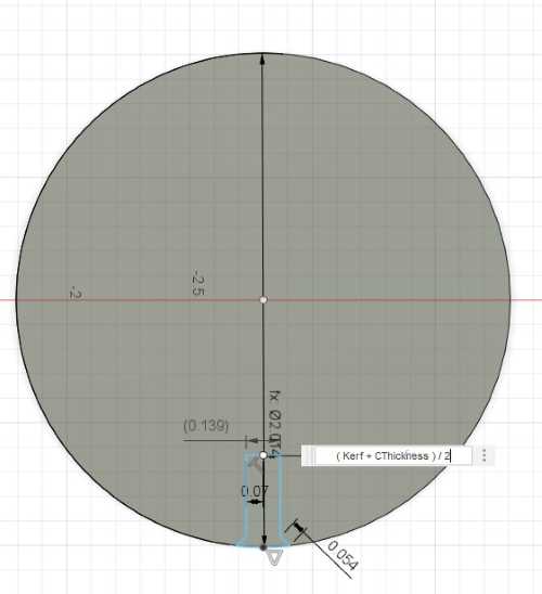
using a parameter to dimmension my pieces
Principles learned from the group project
Some things we learned from the group project that I will definitely use in the future are the Kerf value for the big Epilog laser cutter, the way dithering works, and the difference between the different types of dithering. The kerf value simply needs to be added to each relevant dimmension in order to ensure teh dimmensions are the same or at least similar to how you want them to end up after you have cut your piece. The dithering process was also fascinating as it was very interesting how you can create grayscaled images using just dots. The dithering method I prefered the most was stucki, as it seemed to be the most defined of the methods, and the one I least prefered was bayer. Dithering likely won't help very well with my final project, but it was a very cool thing to learn.