Week 18 - Project Development
Questions to be answered
What has been completed?
What was completed at the beginning of this week was the CAD design, by the end however, everything functioned!
What tasks remain?
At the beginning of this week I still have to finish electronics, and fabricate all the pieces of my project, leaving quite a bit to be down within this time frame.
What has worked what hasn't?
So far, my cad design as well as some networking has worked, the sensor I planned on using to detect where there is a hole unfortunately has not worked, and continued to not work throughout the project development process, forcing me to change plans for hole detection.
What questions need to be resolved?
I still need to figure out how everything will be powered, because that is something I am not very well versed in. Will a single 9 volt battery be enough? or will I need more?
what will happen when?
The setup/ schedule I will be roughly following if everything goes according to plan is the same that can be found in week 16.
Day 1 progress
Today wasn't a hugely productive day in terms of final project, rather more catching up on documentation. THe final design was finished, as you can see above. I also attempted to mill something to mold and cast, but the wax slipped, so I will try again tomorrow, I believe it may have had something to do with the toolpaths I was using, and the subsequent bit I used, I misremembered and used a 1/32 inch flat end mill instead of a 1/8 inch flat end mill. The design went well though, I now had mounts for all my servos, and the dropper mechanism was done. I began a 3D print, but it wont be done until tomorrow. The next few days will be much more eventful however, I simply needed today to have all my fusion designs finished, so that I had a better understanding of how everything would fit together. Thus far I am on track for what I need to do, and luckily I gave myself some extra days at the end too, which will be helpful in the case of a hang-up or issue.
Day 2 progress
Today unfortunately wasn't as efficient as I had hoped. I was having a lot of trouble with the vl53l1x sensor. I tried multiple different options, such as the adafruit circuitPython library and example code, the same code we used in our group machine week project, yet nothing worked. Eventually I called adam to ask exactly what needed to happen with the code for our machine week project, and he told me I needed to have the micropython version 1.18 installed on my Pico instead of the most recent version, 1.20. I changed this, and yet it still didn't work. What I did get done however today was networking both boards together, and getting them to communicate the value of the MPU6050 accelerometer on the seeed to the pico. This was not too difficult, and was a significant step in my final project. I also got more 3D prints done, and did some slight alterations to my design to create some improvements.
Day 3 progress
Today a lot of progress was made. I began the day by creating my aspire file for the housing of the box, and then while waiting for Ryan to add his design to my project, I began a few more prints, and then we both moved on to milling. The mill turrned out great, but as Mr. Dubick later pointed out, I should've used 1/4 inch wood instead of 1/2 inch, because I didn't need to make it that sturdy, and was just making it more challenging for merrit. After the mill was finished, I sanded down all the pieces, and used the domino to create some joints to join both boards together. I double checked to make sure it all looked good, which it did, so I wood glued everything but the top together. While The glue was somewhat drying, I wanted to laser cut the access door for the electronics, so I quickly accounted for the kerf on my design, and went to the laser cutter to cut it out. Once it was in the file, I decided I wanted to add text, so I added "Save the trees", which resonates with the purpose of my project. Once this cut out, I tried to fit it into the cavity I created with my mill, but it was too small. I accounted for kerf too little! I then just took the acrylic to sand it down, and with that, it worked, and it fit very solidly into the cavity. At the end of the day, one of the prints for my dropper mechanism was done, so I tested that with the middle hole, and it worked great! It didn't work so well in the other holes though, so I will have to sand them more later. Merritt also found some vl530x tof sensors, which were simply the previous version of the ones I was already using.
Day 4 progress
Today was a repeat of day 2, it wasn't super great in terms of the progress made electronically. I tried again to use the vl53l0x tof sensor, but to no avail. I even found a library to make it work, but that library for whatever reason wasn't working for me. The tried to get this to work for around 2 or 3 hours, switching pins around, changing the version of micropython that I was using, in concern of having the same problem adam told me about the vl53l0x, so I switched the version but it still didn't work. Then I handed the sensor off to Stuart ot let him try with it, becuase he needed one for his project, and it worked for him, but the issue with it was that it used gpio pins 0 and 1 on the PICO, which I needed for my UART communication between my two boards. Despite this, I tried it on my computer, with the same code as stuart, who followed the same tutorial I did, but it didn't work. I decided I would move in a different direction from there. I wanted to change what I was doing, so now instead of planting a tree whenever a whole is detected, the planted would plant one about every 6 feet, or whatever number I set it to. The reasoning for this, would be that the seeds would not be dropped into a hole that it wasn't supposed to drop into, it would instead drop into the exact distance of the set holes. The upside to this is more precision (hopefully), because from prior experience, the sensor isn't always the most acurate, and the hole could be any depth and the sensor would still work. The seeds already need to be space a certain distance from each other, so it would make sense to do it this way anyway. All this results as is a more coding and calculation intense project. The downside here, it that it could be too precise, and this would result in errors, becuase of what the human did. Overall, I think this is a necessary step, and will likely make this a better project. In the future it is definitely possible for me to use a combination of both. Tomorrow will likely be a big day, and will consist mostly of testing, milling and putting the project all together, and preparing for the end. At this point, the physical portion of the project is nearly done, I jsut need to finish the funnels, and mold and cast the dropper mechanism.
Now, after being at school, I asked chapt GPT to This was the code it gave me
import math

# Constants
ACCELERATION_THRESHOLD = 2.0  # G
GRAVITY = 9.81  # m/s^2 (standard gravity)

# Function to calculate time to travel 6 feet
def calculate_time_to_travel_six_feet(acceleration):
    # Convert G to m/s^2
    acceleration_mps2 = acceleration * GRAVITY

    # Check if the acceleration is above the threshold
    if acceleration_mps2 > ACCELERATION_THRESHOLD:
        # Calculate the time using the formula: time = sqrt(2 * distance / acceleration)
        distance = 6.0 * 0.3048  # 6 feet to meters
        time = math.sqrt(2 * distance / acceleration_mps2)
        return time
    else:
        return None

# Example usage
acceleration_value = 1.5  # Replace this with the actual acceleration value from your accelerometer

time_to_travel_six_feet = calculate_time_to_travel_six_feet(acceleration_value)

if time_to_travel_six_feet is not None:
    print("The time to travel 6 feet is:", round(time_to_travel_six_feet, 2), "seconds.")
else:
    print("Acceleration is below the threshold.")
I decided that I didn't need the section for debugging going over the 2g threshold, because it is highly unlikely merritt's wagon accelerates faster than 44 mph/second, so it would just be useless code. I patched it together with some pieces of code which I used during input week to get a good reading. This code essentially will send the time to travel 6 feet, then the other line of code (which is not yet written) will wait for an amount of time slightly less than that, then begin to move servos, to hopefull drop the seeds accurately.
Day 5 progress
Today was a very large day for the development of my project. I began my day be removing a few more prints, and they all turned out fine. Then once the prints were taken off, I began to work on my code more. Upon speaking with Mr. Dubick, he pointed out that I would only be able to make this work if the speed was consistent, which was a slight issue, that I tried to track before, but it wasn't the most efficient way of working. Then Drew Griggs offered to help with that portion, becuase it entailed calculous, which I currently do not know. The code is fairly understandable, and is a more effiecient and concise way of keeping track of the acceleration. This was the code he helped write below
''' Est_V += ax*Time_Const Est_X += Est_V * Time_Const if(abs(Est_X - prev_drop) > 1.83): com1.send("yes") prev_drop = Est_X sleep(Time_Const) '''
This is some fairly understandable code. It takes the acceleration and multiplies it by the time, which was similar to what I had written last night, then it tried to map out how far it was from where it started, until it reaches 1.83 meters (6 feet). Once it hits that 6 feet mark, it sends a message to the Pico to drop a seed. Once I got this working I started to test with the servos after I began the 3D print for my mold, which would be the piece that I used in the dropper. I found a library that allows for server controlls in micropython, for which the syntax was very similar to the syntax in arduino, making it easy to learn. When I first tried the first servo, it was giving some weird feedback similar to the stepper motor I used in output week. Later after trying to trouble shoot, I unplugged the power wire, because I felt the servo heating up. I plugged it back in, and it started to move somewhat. Then I repeated this a few times, and the servo worked! Next I wanted to test it with all of my servos, so I plugged them all in. After this, I tested the code, and it successfully alternated between each servo, and after each servo, the fourth servo would move. I had to play around with the delay values a bit to make sure they could fully open before closing again. Eventually this worked! This was the code for the receiving / servo dropping code
''' from easy_comms import Easy_comms from time import sleep from servo import Servo
com1 = Easy_comms(uart_id=0, baud_rate=9600) com1.start()
servo1 = Servo(2) servo2 = Servo(3) servo3 = Servo(4) servo4 = Servo(5)
track = 1
def servo_Spin(): global track
if track == 1:
    servo1.write(45)
    servo4.write(90)
    sleep(.4)
    servo1.write(0)
    track = 2
else:
    if track == 2:
        servo2.write(45)
        servo4.write(90)
        sleep(.4)
        servo2.write(0)
        track = 3
    else:
        servo3.write(45)
        servo4.write(90)
        sleep(.4)
        servo2.write(0)
        track = 1
servo1.write(0) sleep(.4) servo2.write(0) sleep(.4) servo3.write(0) sleep(.4) servo4.write(0) sleep(.4)
while True: message = "" message = com1.read()
if message is not None:
    print(f"message received: {message.strip('\n')}")
if message == "yes":
    servo_Spin()
    print("spinning", f"{track}")
    sleep(.4)
    servo4.write(0)
By this time, the 3D print was finished, so I moved onto making the silicone mold for my cast. Unfortunately, I had accidentally missed part of the extrusion in my fusion file, so the slot for the hole went all the way through. I cast this anyway, and the cast turrned out well, the details were all very clearly represented, a testiment to the ability of casting for precision. Once the cast was finished, I began the solid molding process, which turned out well, I added to the purple coloring for a bit more color within the design. The design came out well, and it even looked like a 3D print! I fit it to the servo, and it fit incredibly well, there is a small gap, but so long as I don't use really small seeds, it shouldn't be a problem. Now that everything was desinged, I cast a 2 more times, for the remaining pieces I needed, and they both came out great as well. Then I began work on my PCB. In the PCB there was going to be the same layout I had when I breadboarded. There was an issue here though, the voltage regulator footprint was incorrect to how those within our lab functioned. This took a bit of trial and error to fix, and I only realized this after Stuart pointed it out to me. Then I moved onto the routing, and had another problem, due to the setup of my board, there would be some issues with wiring, so I created a few 0 ohm resistors which were unfortunately necessary. From there that was were I ended the day, tomorrow there will be a strong possibility that the project will be finished.
Day 6 progress
Today I milled a board to begin the day. While milling the board I realized that I had left off a pad in order to bridge a gap, so I tried to simply jump over it with a wire. This didn't work so I tried again, and this time it wasn't adhered well enough to the bed. Finally on the third try, I finished it, again without the pad using a wire and this time the board worked. I tried to run it using the same code that I used with the breadboard. This worked wiht my computer, but it didn't work when I tried to run it off of the nine volt battery. The code worked, but the servos were unable to move
Day 7 progress
Today I began by asking Mr. Durrett what might have been the problem with my board, and I checked the voltage, and the servos were not getting enough power to move. Mr. Durrett suggested I use 1 or more buck converters to make sure that I could get enough amps and voltage to power my servos. I redid my circuit and milled another board to add two buck converters in, which would power my project. After I milled and soldered the board, I was still unable to get this working, even with the two buck converters I used in tandem with the other battery. I then decided I would make another pivot to another different idea for powering, a USB power bank. I figured that since this is able to run off the power on my computer's USB, it might be feasable to try and run it off of the power bank, because it would hopefully supply enough volts to run the servos. When I plugged it in it worked! I used the original board, but it managed to work!
Day 8 progress
Today all that I did were some final touches to my project. I cut a longer t-bar for the hole filling rake, as well as remilling the board to be much more clean and concise. The board now looks so much better and is smaller as well, as another added bonus. To mount the board to my project, I had printed some small pieces to fit on the corners of the board to make it stay still. I simply drilled them into my box, and the board could no longer move! With those final small touches my project was now finished and I could move onto creating the videos and final slide!
Creation photo gallery
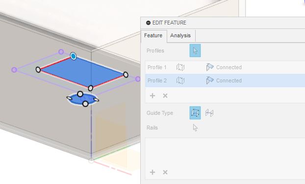 designing the CAD
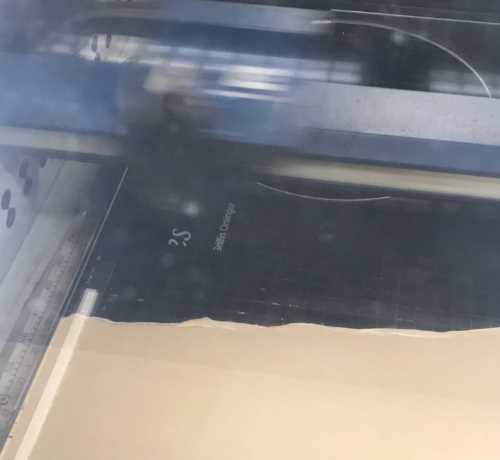 Laser cutting the panel
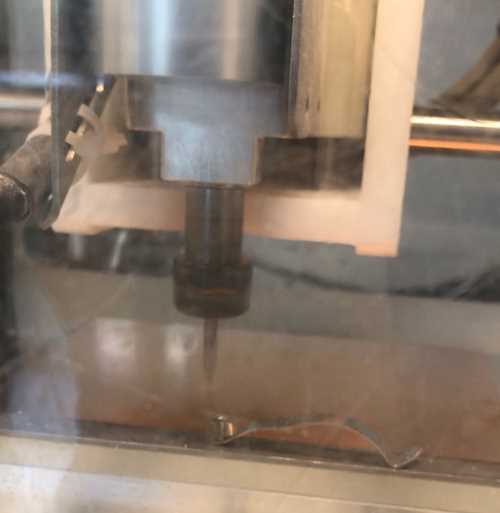
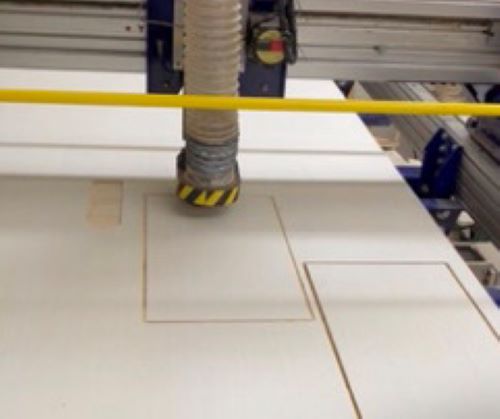 CNCing the box
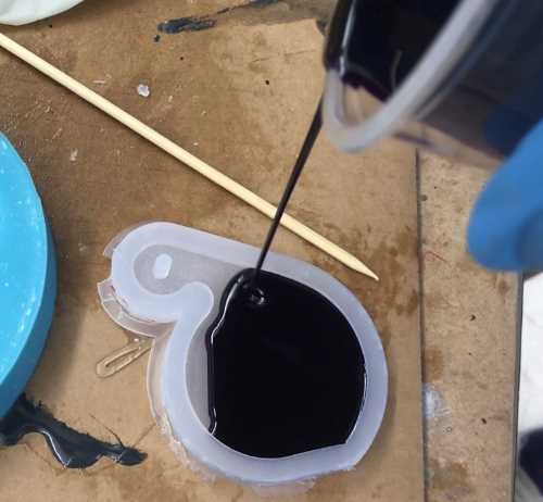 Pouring the mold
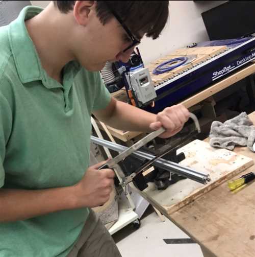 Cutting the T-bar
 Milling the board
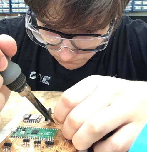 Soldering the board