Week 10 - Machine week
Our group's initial project Idea was to create a table cleaning robot. I initially theorized that we should use a robot that had a rag on a servo that would move up and down the table to clean it. This Idea was quickly shut down, as it was more complicated than it needed to be. The next Idea that was suggested was to have a spinning rag on a dowel to move. Before we tested it all we drew a bunch of designs for how everyhting would work machine.
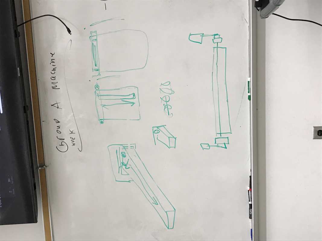
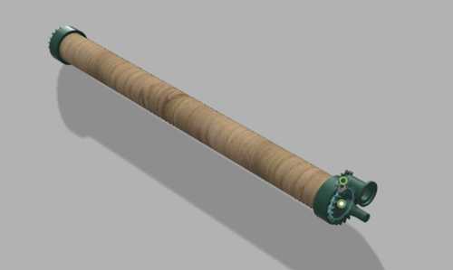
There would be a rack and pinion to drive the roller up and down, and wheels would be on the side of the table to move the machine back and forth. Eventually after designing and brainstorming, we decided to not use the rack and pinion for Z movement, but rather 2 lead screws on each side of the mechanism. We measured the width of the cafeteria tables at our school(the tables we wanted to clean), and took that into consideration for our design. I was in charge of creating the sweeping mechanism, so I used the gear tool to create a gear on the end of the dowel, also making everything a 1:2 gear ratio, in order to give the motors more torque.
The motor we planned on using was a DC motor, but then later, Mr. Dubick told us we should've tested everything before designing. When we tested it, the motor didn't have enough torque, and it still probably would'nt have worked with a 1:2 ratio. SO we then decided to go down a different avenue for what we needed. Our group decided upon using a squeegee in the back to just pull off the food. I designed a new design now, completely redoing everthing previously done. For this next design I found two squeegees we would use for the project that would encompass the whole table. I designed everything around that. This next design was much more simple than the previous itteration. All that needed to have was the mounting brackets for the squeegee poles, as well as two pieces on the sides that would be used to move the contraption up and down.
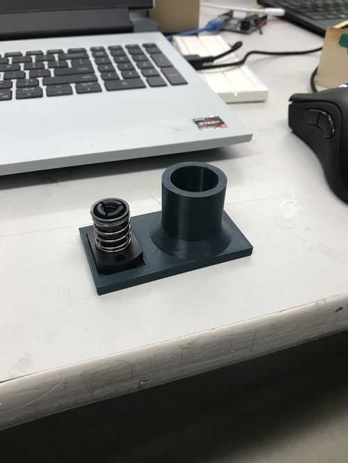
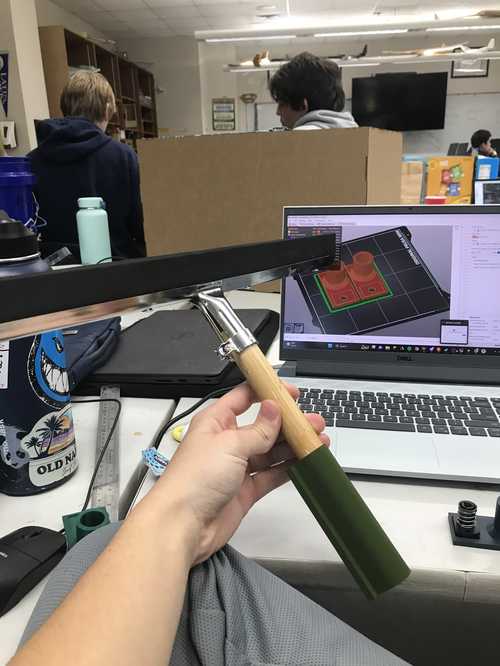
My plan was to cnc the board, and print the pieces, heat sink them with screws, and then screw them into the cnc'd board. I designed the mounting pieces with reguards to head sinking, so the screws would be easy to put in. I had to wait until we recieved our lead screw stepper motors to begin the design on the contraption to move the machine up and down. I took inspiration from our regular sized prusa printers, and used a contraption similar to that when designing them.
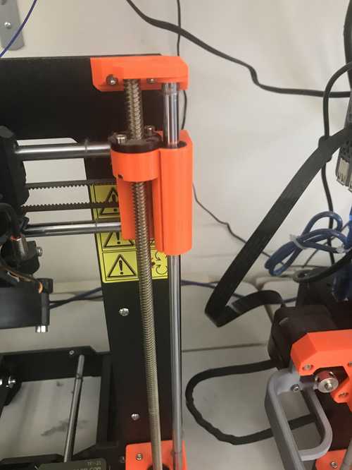
The first two prints I did didn't work, because the caliper I was using was not precise enough for me to get a good measurement. I found a better caliper and got better measurements slightly offset by 1/100th of an inch for clearance. I also designed the holes for the board, which Jed and I laser cut and glued sheets together. The holes overlapped so I used a drill to drill out the holes and they fit with the design. Puting everything together was very frustrating as we had an issue with the guide rails. The guide rails couldn't be cut, because they were hardened steel, and we didn't have anything else to use so we had to adjust the rest of our setup to compensate. Drilling through the T-bar was extremely difficult and we had many issues with it for whatever reason. Eventually we got it cut and moved to assembly. Putting everything together was a relatively simple task, but everything needed to harmonize well in order for the project to work. We got everything together and it worked (after a few modifications)!
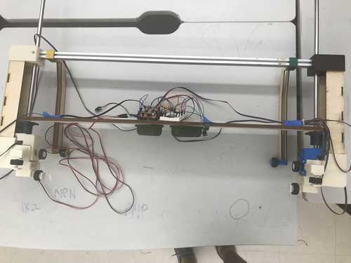 Final project put together