Week 6 - Electronic Design
Soldering a dev board
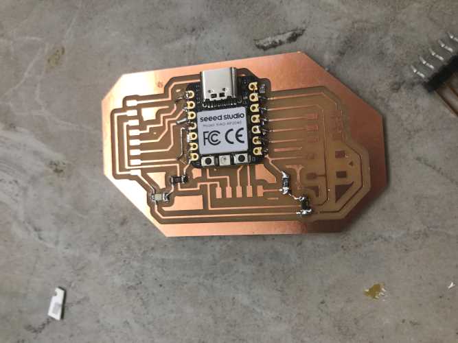
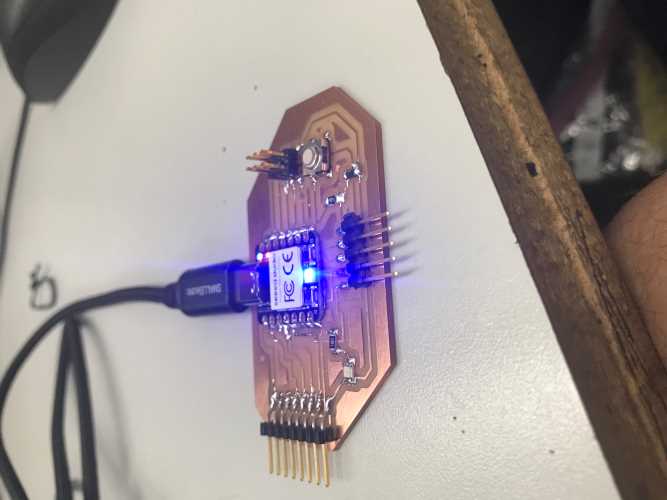
To begin this week I soldered a dev board that Mr. Dubick gave us, which can be found here. The method I used was placing a dab of solder on the pad, placing one pin of the component on it, then once it was solidly into place, I soldered the rest of the pins of that piece on. This soldering job was fairly simple, but it used components I had never used before such as a 0 ohm resistor to bridge over gaps. The order I soldered everything on went from smallest componenets to the largest ones in order to make the job easier to solder.
Designing boards in Fusion360
To design the board for this week's assignment, I started by using a tutorial Mr. Dubick gave us, which can be found here. I learned how to import componenets, link those componenets together, label components, and also group them. This tutorial was very helpful, despite how fast it was. Here are some images of the first part of the tutorial-
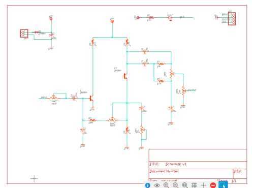
In the later parts of the tutorials I learned how I was able to interface these boards with designs I already had in Fusion. The interfacing was a huge upside with this, and allowed to get a sense of scale within the design.
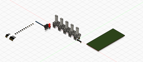
In the final tutorials I learned how to order and link the componenets together.
Designing boards in KiCad
To begin, I downloaded the fablab KiCad library found Here
I then used tutorials found on Tech Explorations
In the tutorials I learned how to associate the toolpaths, make nets, and create a physical board that could be cut out. Personally, I was more a fan of using fusion, because you didn't have to associate the symbols with their toolpaths, so in the future I will be using fusion as well, making the designs integrate is also a very good om fusion compared to KiCad.
Creating my own single use board in Fusion
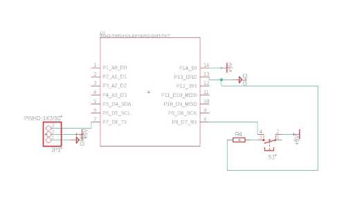
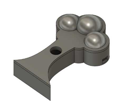
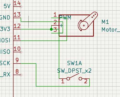
The components I chose to use in my design were the button and servo. I made my casing special here as well, opting for a design on a tree which fits with my goal of my final project saving the environment by planting more trees or plants. The design of the case was what I did first in order to get the same shape for my board. I created a lid as well, and a little hole in the center for where you could push a button that would enable the servo to move. I made a simple sketch in fusion, then moved onto the electronic design portion. I only needed 4 total components in my circuit, the button, the resistor for said button, the header pins for the servo, and finally the seeed.
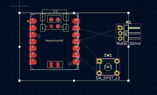
I began to follow the workflow I learned in the tutorials, and started by placing down all the components I needed. After the components were placed, I created nets to each of the components to visualize how each componenet would react with each other.
Once this was finished, I moved on to creating the actual schematic for the design. In order to do this I first had to design the case though, which I opted for a tree. I ported that board into my schematic design so I could see what the board would look like when it turned out, to accurately place all my parts, and to get the actually shape of the board correctly.
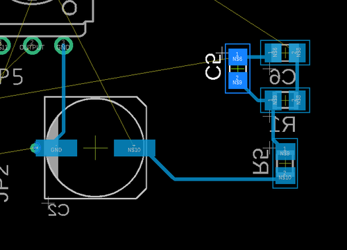
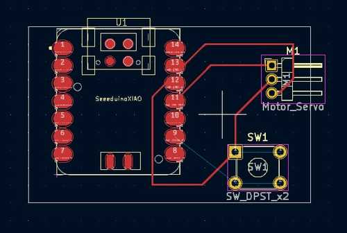
I finally had the board shape designed, so now I could move on to the actual wiring of the board. There were a few issues that I encountered here, mostly just figuring out how to not have wires overlap each other. Eventually I managed to get a design that worked, which was helped by creating wires under components, which was something I hadn't thought of doing before.
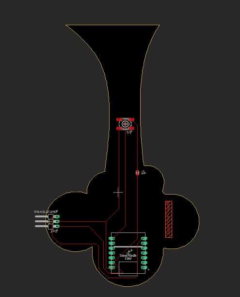
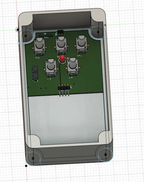
Now all that was left was to create the slots in the case where the seeed could be hooked up and where I would hook up the servo. This was accomplished with just some simple offset plains and rectangles. This is the final design of my board in it's casing.
The Fab library for Eagle can be found here
Creating my single use board in KiCad
After following the tutorials I just used what I had learned to creat footprints and paths to make my board come to life. The button I found was a lightly different footprint than I wanted, but it still functions the same. Here are some pictures of me making the board in KiCad
Simulating the board in Wowki
To simulate this board, I simply set up the board similarly to how it was set up in my schematic, I ran a bunch of code through it that was designed to move a servo when the button was pressed. I needed to use this website to learn how to change resistor values. This was fairly easy to use. I used a similar piece of code as I did in week 8, which just moved a servo when the button was pressed, and did nothing when it wasn't.
Group project
In this week, I used the multimeter to see how much voltage was going through different parts of the circuit we were given at the beginning of the week. The link to our group site can be found here.