Week 4 - Embedded programming
Arduino
Arduino was what I was most familiar with going into this week. In my engineering classes, this was our main programmer, and I had only every used the arduino before taking that class as well. The only thing I had under my belt besides the arduino for this week was the 412 chip, which we had programmed in prefab. The usage of the arduino is simple, and adapting your code to what you need to do is easy as well. Blinking an LED with the arduino was simple, all you had to do was load the blink example, and then you connect an LED to pin 13, which is the pin defaulted in the example, and use a 330 ohm resistor connected to the ground pin. This is what this example looks like:
hereThe next task we were told to do with the Arduino was use an input to provide an output. Here I struggled a bit, despite my prior knowledge. I chose to use a photocell resistor to modify the light level of the LED to be the corresponding value the photocell resistor received. Before going into this, I knew that there was a much higher value the photocell resistor could measure than the LED could output. I knew the LED's output max was 255, but I wasn't sure what the photocell resistor's was. I searched a bit on the internet looking for photocell resistor code with an LED on arduino, and I found this instructables tutorial which told me what the max value of the photocell was. I was also unsure that I had the correct wiring of the photocell resistor, but I managed to get it right, and verified this with the tutorial. I modified tehe code to use analogWrite and not digitalWrite, so that the LED would output different brightness levels. This is the final coed I ended up with
const int pResistor = A0; // Photoresistor at Arduino analog pin A0
const int ledPin=9;       // Led pin at Arduino pin 9

//Variables
int value;          // Store value from photoresistor (0-1023)

void setup(){
 pinMode(ledPin, OUTPUT);  // Set lepPin - 9 pin as an output
 pinMode(pResistor, INPUT);// Set pResistor - A0 pin as an input (optional)
}

void loop(){
  value = analogRead(pResistor)/5;

  //You can change value "25"
  analogWrite(ledPin, value);

  delay(100); //Small delay
}
Programming a 412 chip
Before Fab started, Mr. Dubick walked us through how to program an ATTINY 412 chip. We programmed this chips using the arduino IDE, and using jtag to use arduinos as a programmer. There are only a few differences when programming the 412 compared to the Arduino, specifically what pins you use as outputs. We used the Arduino as a programmer, by uploading jtag to our arduinos. After the Arduinos were uploaded with jtag, we could begin the process of programming the actual 412 chip. The first step I took was looking at the pinouts for the chip.
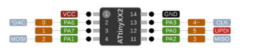 The orange blocks are the pins you use when programming using the Arduino IDE, which is what I used
Mr. Dubick instructed us that pin 6 on the 412 chip always needed to be plugged in to pin 6 on the arduino. Pin 1 was the power pin, which needed to be plugged into the 5 volt power, and pin 8 was the power, which needed to be plugged into the ground pin on the arduino. The pinouts were easy to understand, so I tried to make it blink with the same code as with the blink example from arduino, except changing the output pin to pin one, which corresponds to pin 4 on the 412. This was the code I used
void setup() {
  // initialize digital pin LED_BUILTIN as an output.
  pinMode(1, OUTPUT);
}

// the loop function runs over and over again forever
void loop() {
  digitalWrite(1, HIGH);   // turn the LED on (HIGH is the voltage level)
  delay(1000);                       // wait for a second
  digitalWrite(1, LOW);    // turn the LED off by making the voltage LOW
  delay(1000);                       // wait for a second
}
The 412 chip was easy to use with the photocell resistor as well, I only had to switch which pins were slotted as the photocell and the LED. I changed const int pResistor = A0; to const int pResistor = 0; and const int ledPin=9; to const int ledPin=1;. The change was small, but having to add everything onto the 412 made it more difficult wiring wise. The complexity programming wise was the same however.
Raspberry Pi PICO
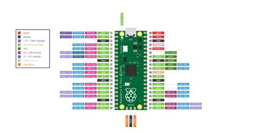
The final chip I decided to use was the raspberry pi PICO 2040. There was a much bigger difference here compared to the other chips. The PICO was much more difficult to control than the 412 and the arduino. There were many more pins which was daunting, and there were 3 seperate power ports, so I was unsure of which one I should use.
I struggled a lot with the PICO, mainly due to it not connecting to my computer. The way the PICO connects to devices is by holding down the button on the top then plugging it into whatever device you are using to program it. Mr Dubick was the one who originally told us this. You had to do this in order to connect it with your COM ports on arduino. This initially worked fine with me, enough to program the LED to blink.
Later on in the week however, when I tried to program the PICO in order to respond with a photocell resistor, I couldn't locate the PICO on any of my ports. This was a major problem, as without it showing up on my ports, I could do nothing in order to program it. I tried restarting multiple times, changed the cable I used and even changed which PICO I was using to no avail. Eventually I tried the PICO on a different PC, and I could connect to the COM ports there for whatever reason. I was still unable to get the photocell resistor to work, so I decided I would come back to it. Next I tried to use a pull down resistor to tell the LED when to blink. This worked first try, here is the code I used to do this
int pushButton = 14;
int ledPin = 15;

// the setup routine runs once when you press reset:
void setup() {
  // initialize serial communication at 9600 bits per second:
  Serial.begin(9600);
  // make the pushbutton's pin an input:
  pinMode(pushButton, INPUT);
  pinMode(ledPin, OUTPUT);
}

// the loop routine runs over and over again forever:
void loop() {
  // read the input pin:
  int buttonState = digitalRead(pushButton);
  // print out the state of the button:
  Serial.println(buttonState);
  digitalWrite(ledPin, buttonState);
  delay(100);        // delay in between reads for stability
}
This is a modified version of the arduino example "DigitalReadSerial"
Using Thonny with the PICO
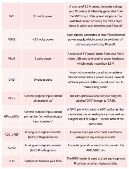
The next step in my embedded programming journey was programming using microPython in Thonny, a python IDE. I underwent a set of tutorials given to us by Dr. Taylor. Dr. Taylor laid these out for us in slideshow form which made the more digestible, but reading portions of the book helped me to better understand how everyhting worked on the PICO, such as which power pin output which voltage, rather than cycling through all three untill I found one that worked.
Thonny was described as a beginner microPython language, which makes sense, as the coding is very simple, and there are lots of tools to help debug code. The IDE was fairly helpful, but when I was trying to get the code to run on my PICO, it wasn't working for whatever reason. I then looked at Adam Stone's site where I learned I had to change the interpreter in order for Thonny to interpret which libraries I used.
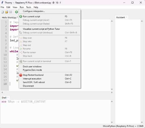
When I switched the interpreter to my PICO, it worked! This is the code I used for blinking my PICO using microPython
import machine
import utime

# Define the onboard LED pin number
led_pin = machine.Pin(15, machine.Pin.OUT)

# Loop to blink the LED
while True:
    # Turn the LED on
    led_pin.value(1)
    # Wait for 1 second
    utime.sleep(1)
    # Turn the LED off
    led_pin.value(0)
    # Wait for 1 second
    utime.sleep(1)
This was code that Dr. Taylor gave to us in his tutorials
Library-less programming (bare metal)
To begin this section of this week, Mr. Dubick gave us a slideshow explaining how "bare metal" programming works. Essentially, you are referencing bits of the microcontroller's memory and directly turning pins on and off. The process is designed to use less memory as well as to run faster. I started trying to do this using Jack Hollingsworth's page for the 412 chip after I had searched to no avail to find how to use the ports. I was having trouble locating where I was supposed to look to find the specific memory locations to ping the pins. I found where to look while looking at Adam Stone's documentation on the subject. This was fairly simple to understand, as it made more sense than typing out all the numbers. The next step I tried was actually using jack's code, I plugged it into the 412 and it worked. I then tried to write my own code using adam's as an example, but it didn't work.
Group project takeaways
The group project this week was to compare the architecture of different microcontrollers. The different microcontrollers all had different strengths, such as the number of pins each chip provided, the programmer for each of them, and the languages supported by each of them. Chat GPT was very heplful with this, because it even told where you could find the information you looked for. Each microcontrol even had their own built in features, such as the ESP32-S2 had built in wifi capabilities, and the RP2040 had a built in temperature sensor.
Link to the group project page