Week 8 - Electronics production
Milling the board
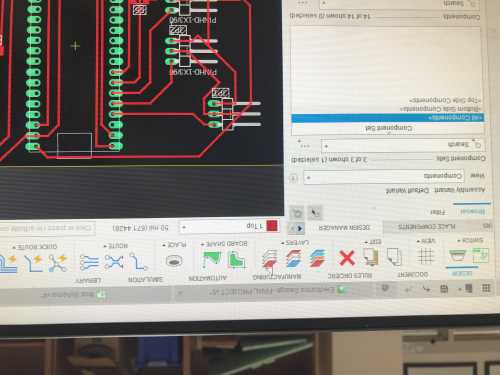
Our lab uses the Bantam software along with othermill desktop milling machines in order to create our boards. The first step of this process was to upload the schematic I had previously made in fusion into the bantam software. I exported the manufacturing details from the schematic, then uploaded the file into our drive and downloaded it again on the computers connected to the milling machines. Ryan Kim told me exactly which files I needed, which was not the DXF I originally tried to use. Once I had the files, I began the process of using the actual milling machine. To begin with, I uploaded 2 seperate files that were in the original folder I exported, and then I measured the material I was going to use, and inputed the correct values into the bantam software. I also selected the bits I would use, which where the 1/64 inch bit and the 1/32 inch bit.
I placed Nitto tape on the back of the board and placed it on the bed lined up as close as possible to the left side of the bed. I changed the offset of the material to 0 for everything and probed the material thickness to finish setting up the material. In the past, I did this step without making sure the material was electrically connected, which resulted in a broken bit. I probed the bit too, since I changed it in the process. All I had to do here was place a piece of foam underneath the bed, and then I loosedn the collet with 2 wrenched until the bit came out. I placed the new bit into the machine and tightened it again this time, then moved it over an empty piece of bed. I let it run, and now it knew where my tool was. I could now hit click to mill and it would mill all it was set to. I changed the bit in the middle of the mill in order to more efficiently mill out the board. When it was done this was what it looked like
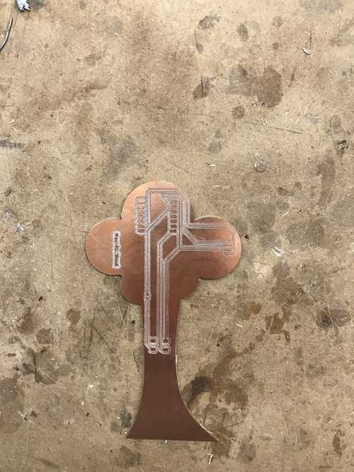
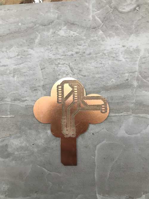
The traces had ripped, and I needed to redo it, so I tried to do this again with just using the 1/64th bit along with less clearance between the traces.
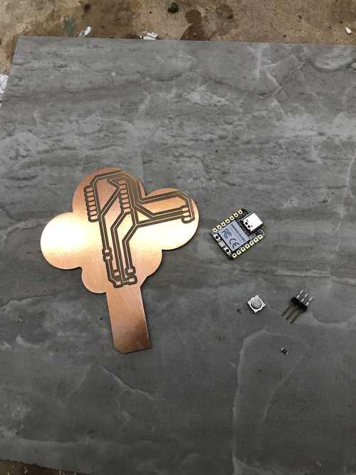
This also didn't work, so I decided to change the trace width in fusion from 6 mils to 12 mils. When I milled this I also made it smaller in order to fully fit onto the smaller machine while still maintaining the right shape. This one milled out corectly, but there where lots of burs leftover.
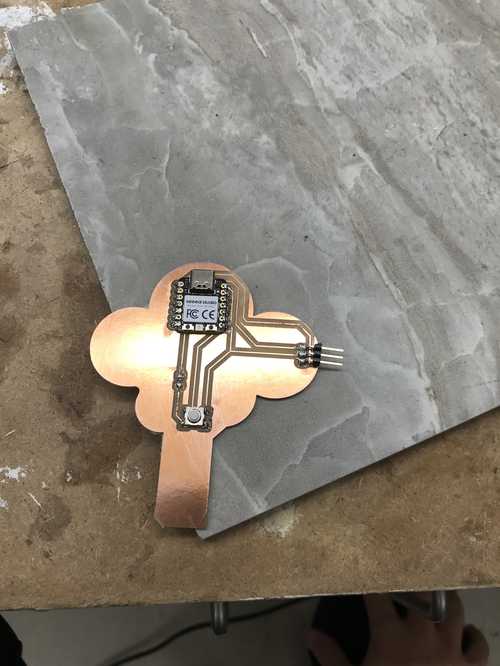
I sanded these off with sandpaper and proceeded to put the components onto the board. To solder, I used the method of placing a dab of solder, then moving the component on top of the solder then soldering the rest of that component's pads. For the rp2040, I had ot put a special tape underneath it, as told to us by Mr. Dubick. This was the final soldered board
Generating the toolpath files
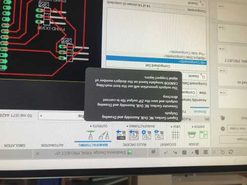
to generate the toolpath files for milling the board in fusion, it takes a few simple steps. First, when on your PCB design, switch to the manufacture tab
Once in the manufacture tab, select the export as gerber option
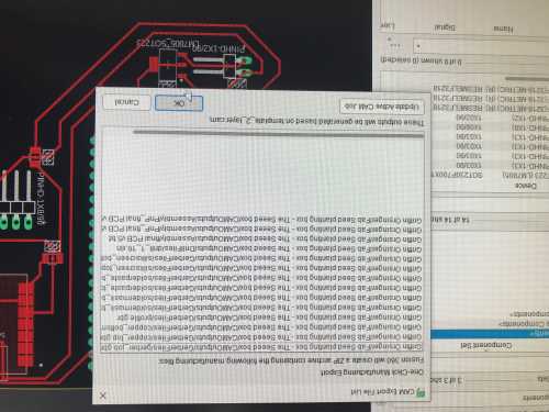
select ok and where you want to save it to
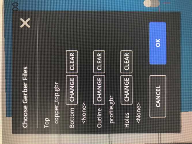
Now extract those files to use in the bantam software. First click the open file button in bantam, and make the top the copper_top.gbr and the outline profile.gbr
Then continue and select the bits your are using, below are the defaults I typically use, except the .005 engraving bit, which is only for when I need very small portions milled.
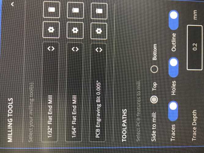
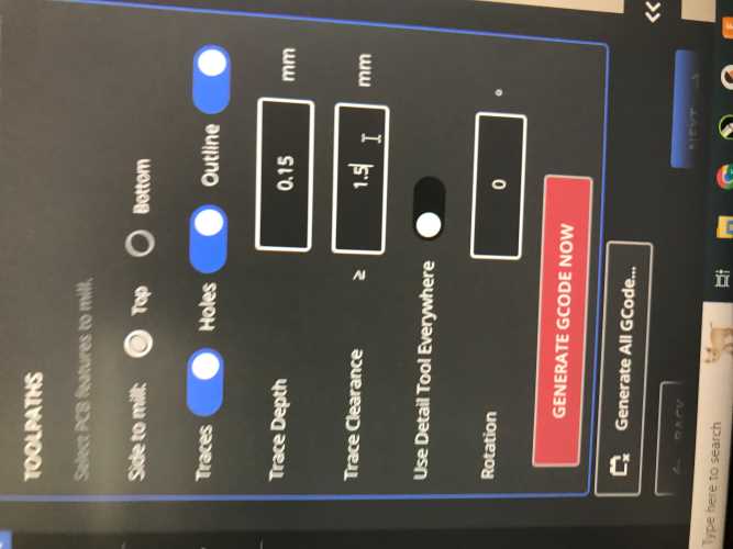
Next change the trace depth to .15 mm and clearance to 1.5 mm and select generate gcode now.
Now all you have to do is follow the other setup steps, such as material setup (which is just inputing the dimensions of your stock) and the zeroing/changing of the bit then you can mill!
Programming the board
The main purpose of this board was to learn how to use a servo, and I also included a button as an input. The first thing IO tried to do was go to chat GPT to get it to tell me what I should do. I asked it ot program a servo to move when I pressed down a button. I inputed the code into the board, but it didn't work. I scrapped the button for now, as the servo was more important to me, so I asked chat GPT to just give me a program for a servo. The code it gave me again didn't work, even when I modified the pinouts. I thought there was something wrong with my board, but I couldn't find anything. Later that day, Adam told me that when he was using his rp2040, his pins were slightly offset from what the pinout diagram said, so I decided to test each pin number to make sure that nothing was wrong with the board before I redid it. When I tried pin 1 it worked! I used code derived from chat GPT, but it was mostly just for reference.
Next I tried to do the button, but earlier in the week I ripped 2 of the buttons pads off when being paranoid about the placement. The issue I had was the button was just constantly sending signal, so my classmate Dylan Ferro told me that I might've had my schematic slightly wrong, and the buttons were not in the right place. The button was constantly activating even when I didn't want it to, but I had finally gotten things to work, and plan on doing further research during inputs week into exactly how pulldown resistors work.
Group project
This week for our group project I milled out the board to see just how small we could get the traces before they tore. We ended up getting them very small, so I can make traces in my designs really small so long as I have a decent bit mill with. Link to group project