Week 7 - Computer controlled machining
Designing the file
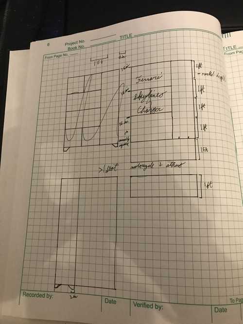
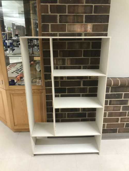
For this week, I wanted to design something in order to display a bunch of lego sets that I have built in the past. My initial idea going into this week was to make a honeycomb-like shelf in order to store them all, but when I truly thought about it, it seemed implausible, joining three different joints together in one spot, so I opted for an easier design. My key features of this design were going to be the tall right pocket which would house my Lego rocket, three portions to the left of that for my various cars as well as taller sets, and final a long portion at the bottom of my case for other legos, mostly small ones. Here is the sketched design of this:
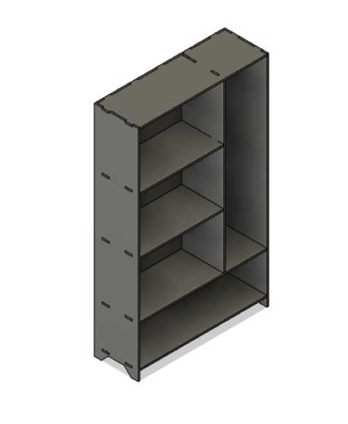
Once I had this design I began using fusion to design it to see how things would work out with tabs. I made many different tabs, and used parameters all centered all around the maximu,m heigh of my shelves. The biggest issue with designing that was more so an annoyance than an issue was creating the tabs and then the slots for the tabs. I had to create a sketch then extrude twice, which was probably not the most efficient way to do things, but it worked eventually. Another issue I had was creating the pattern that I used for the longer pieces of wood. I should've probably designed it in a way that didn't use a pattern so it would be able to better translate when I scaled it down. This did eventually become a problem, as the tabs failed when I scaled it down then back up
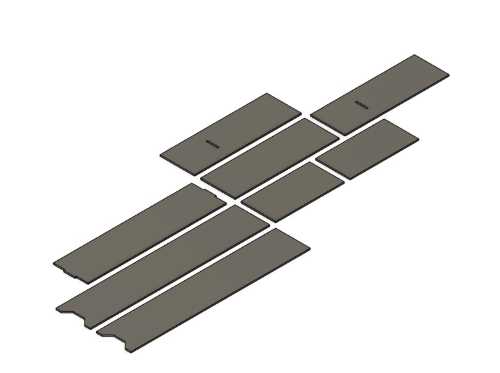
The design did work in the small version though, despite that it didn't scale up correctly. I tried to export this as a DXF file next, but it didn't export correctly, because I tried to do the whole assembly at once, which was pretty dumb of me. Somewhere in this time Mr. Dubick suggested another way to join the boards together, using dowels, as he had the machine to do that. I thought this was a great idea, so I switched my design to make it more sleek of a design. I drew all the new pieces flat in fusion, using the same (or as seen in the future, similar) dimensions. I took these dimensions and exported them to the laser cutter to do a test cut after I had each piece scaled down.
When I cut the pieces out, there was an issue. I was putting the pieces together, in the approximate positions they should have been in based on the size, but when everything was together, the issue was that the sides were too long, meaning I had dimensioned it wrong. I changed the dimensions in fusion then, but they had worked when it was in full scale, so I changed the dimensions. Mr. Dubick told me I should still have at least one tab, so I changed my design slightly in order to make the tabs reincorporated. I cut this design out on a smaller scale, and it worked perfectly!
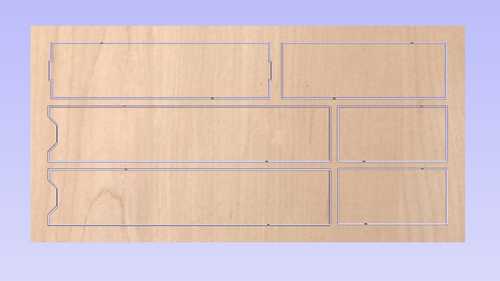
After I had this, I uploaded my design as a DXF to aspire, the software our lab uses on our milling machines. In aspire, there are a few things that need to be checked before the file works, the job size, which should be 96 X 48, the z zero position should be off the bed, and there should be no XY offset. After all these material settings were set (my material thickness was .4625 in.) I started positioning everthing on the sheet I would be using. I now had a problem, as I couldn't fit 2 of my pieces on the one sheet we were given, so I asked mr dubick, and he told me that I could split another sheet with Adam, as well as Dylan. Once I had everything imported into aspire, I made sure to close all my vectors, then set everything up to where it was supposed to be. I used fillets to make sure everything would come out clean, including a T-bone fillet on my inner slots for the tabs since it wouldn't let me do a dogbone due to the width of the slot, and if I didn't include it, it would result in the tabs not working. Now that everything was good, I generated a toolpath, which was what the machine would run. The step down/ number of passes was 1 more pass than the width of the bit, so for a 1/4 inch, it was 3 passes since my board was 1/2 plywood, which translates into 1/6 inch stepdown. For the feedrate, it was 250 inches/ minute, and the plunge rate was 20 inches/ minute. Mr. Dubick checked over my toolpath and said I was good, so now I was set to mill. I had two toolpaths, a vector toolpath, which was cut on the outside and used to create the bodies, and a pocket toolpath, which was for the slots for the tabs.
Milling the board
CNC workflow
Dimensions: 3/4 inch thick plywood for furniture to sit or stand on.

Always 2 ppl. Inside at once.

Use parametric design

Already have shopbot workflow

96in(X) x 48in(Y) shopbot.

Use single sided

Make sure you turn offset off, unless there is some other reason for it to be on

Starts at the bottom left corner of the shopbot

X is the long side - 96

May say open vectors when you import an svg - this is a problem
Join is how you fix this

Use dog bone fillet for your corners, do this for space.

Toolpaths are what are used to cam

Make sure z zero is correct, xy datum and thickness are all correct

The menu to open toolpaths is on the right side of thee screen

Z comes off the machine bed unless, engraving

Machine starts at the bottom left corner

Start depth is material thickness

Bare minimum is 1 pass up from bit width, with a hardwood increase the passes to about double

Profile you want to be on the outside, on a pocket you want to be on the inside

Use tabs in order to prevent the board from kicking out of the machine

Tabs are a thin connection to the bottom of the board

Put name, version, and what you are making in the naming section at the bottom of the toolpaths menu NO SPACES

Once the profile is correct, save it as an aspire file and send it to Mr. Dubick and doctor taylor.


Make sure the tool isn’t loose
Check to make sure the z is off the table, then go to home the spindle
Use JZ to move the z
J2 to move X,Y
C3 to home the machine, set to the original machine origin.
Z off the bed, move the spindle to a spot more central on the table.
Place the plate underneath the bit
C2 to get the z homed
Put the plate back
J2 0,0 takes back to the origin
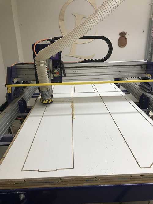
To mill my pieces, first we zeroed the bit. To do this I homed the mill, and moved it more towards where the cut was done. I placed the little probe down beneath the bit and then zeroed it. Once this was done, I moved the spindle so I could place my material down. I used a special nailgun in order to anchor the wood down, making sure the nails were not placed where I would have cut out material. Next I ran an air cut, to make sure the placement was correct, which it was on both jobs I ran. Now finally I started the actual cut, and I just sat with someone else in the room while it cut.
Once it was cut, I took a chisel to remove the tabs and take all the parts off of the board.
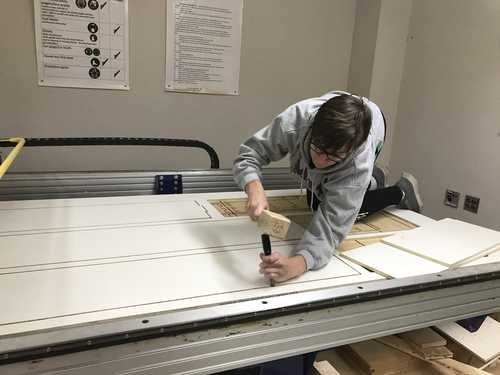
Once I had everything off, I sanded it all down and tested the fit of the slot fit joints to make sure they worked correctly
The Joints worked!
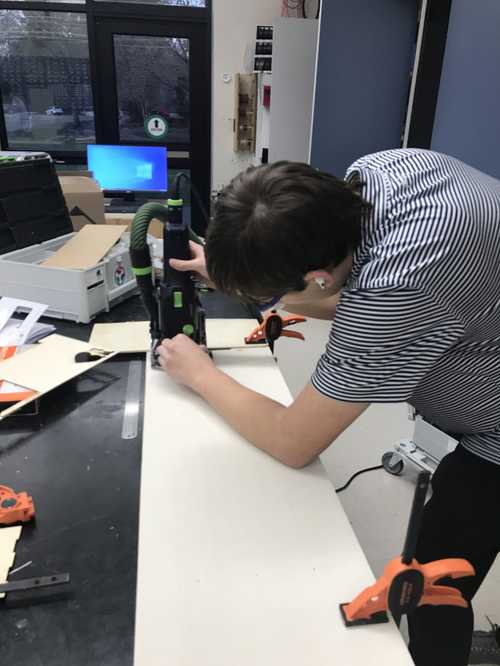
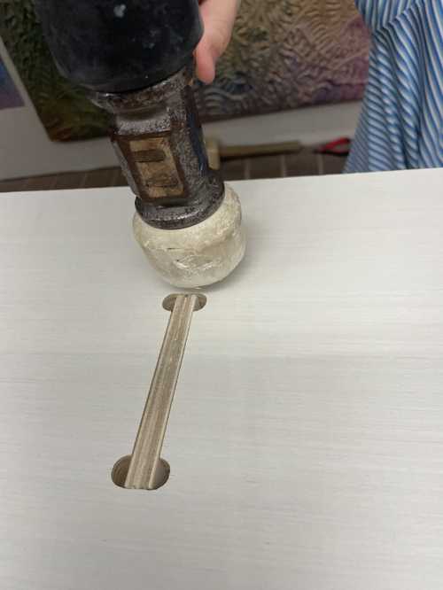
Using the domino
The domino is a tool we have in our lab that creates slots to use dowel-like objects in order to slot fit pieces together. The usage is easy, just adjust the settings to fit right into where the slots need to go, and then you move the domino into the board slowly to create the opening. This was an easy process to learn, but took a little more calcultion when inserting slots onto the larger faces of the board.
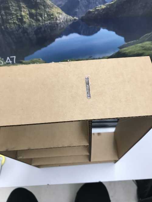
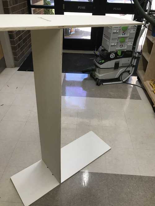
Assembling the pieces
To assemble everything I first started with the left side board, and placed everything on top of that except for the board that slot fit with the divider. I assembled the divider and the slot fit board, then placed these onto the shelves. Now I had a problem. Once I started to place the other side board, I realized it was warped, and therefore wouldn't fit flush with the ofther parts. The same problem was true with the top board. Mr. Dubick told that at this point I should just use a nail gun or wood glue to hold it together. I came back another day and then used the nail gun, which was a very similar use process to using the nylon nails we used to fasten the board to the machine, except you had to lubricate the nail gun before using it. I took a few of the dominos out of the wood to make putting it together easier, and this worked, I just had to avoid where all the dowels were. For the top piece we tipped it over and placed the slot fit piece in first.
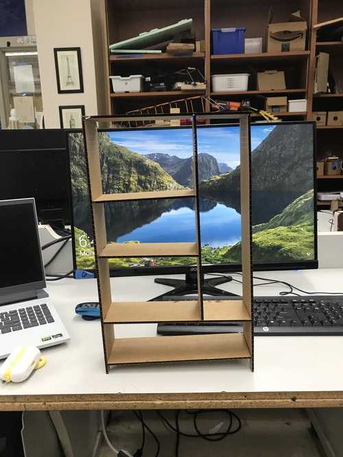
Once the piece was in I tried the nail gun again after taking some dominos out first. The final thing worked! I used a few more nails afterwards to make things more stable then. Here is the final design all put together!
Group site
The group site for this week can be found here