13. Casting and Molding
This week I learned about designing CAM toolpaths in Fusion360 and experimenting with different types of molds with additive and subtractive manufacturing (SLA vs. milling). You can find all of my files here.
Assignment
group assignment:
-
review the safety data sheets for each of your molding and casting materials, then make and compare test casts with each of them
-
compare printing vs machining molds
individual assignment:
-
design a mold around the process you’ll be using, produce it with a smooth surface finish, and use it to cast parts
-
extra credit: use more then two mold parts
PLA Filament 3D Printed Mold + Cast
The first mold I made was a two-step process, between 3D printing a mold (additive) and pouring the soft cast.
Designing a Mold
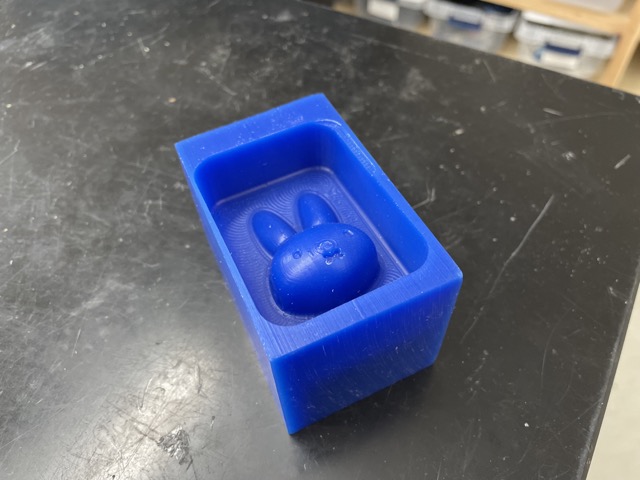
For my mold design, I wanted to continue with my miffy theme, so I inserted an image using the canvas feature and began using the create form tool to model its general shape.
I created a symmetrical line and applied the modify tool to mold the design into what I wanted. Then, I applied the combine tool (subtract) to create the mold.
Here is what it ended up looking like:
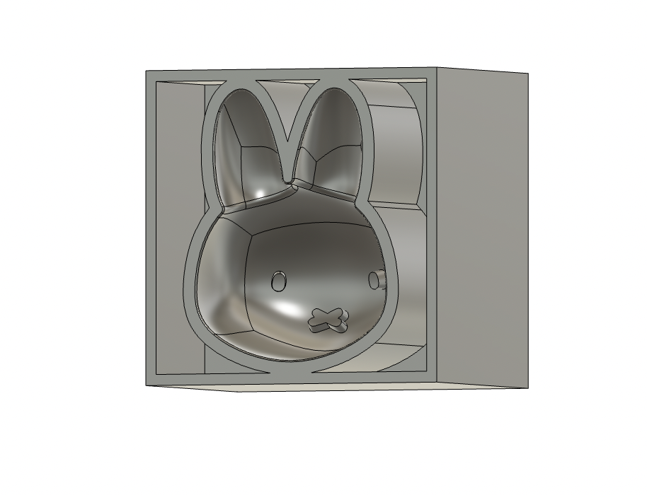
NOTE: I made two main versions - the one above has an offset + extrude and is produced with additive manufacturing.
I saved this as a .STL file and imported it into PrusaSlicer to generate a g-code. For the sake of efficiency, I selected .15 mm speed.
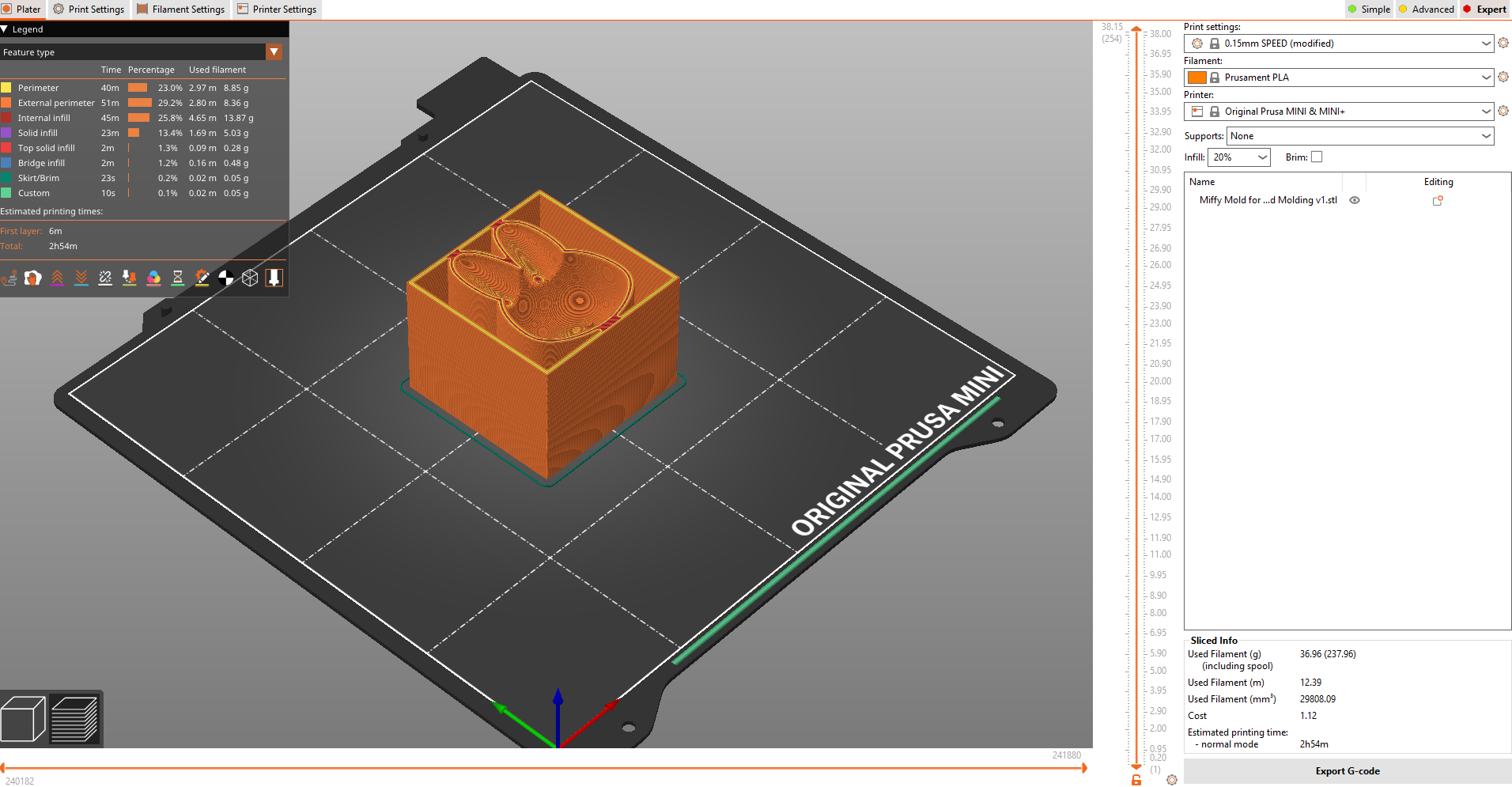
For more information, refer to my 3D Printing and Scanning documentation.
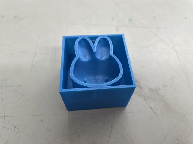
Besides a couple of stray strands from the filament (which I removed with a heat gun), the 3D print turned out great!
Mixing and Pouring Moldstar
Because the filament had created a hard mold, I needed to do a soft cast. For this, I used the 15 Slow Mold Star Series.
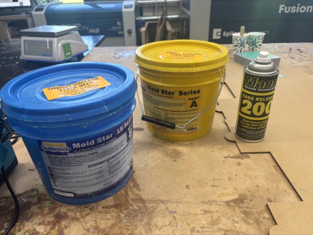
Before mixing parts A and B together in a 1:1 ratio, I stirred each part for a couple of minutes. Then, with the help of Landon Broadwell I slowly poured and combined them.
The gloves are too big on my hands lol.
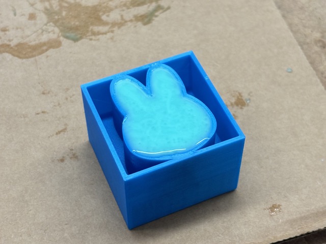
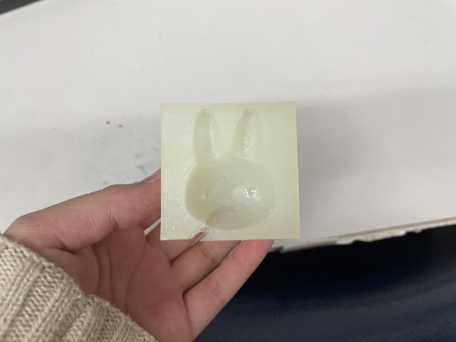
I noticed that a couple of air bubbles were forming during this process, so I tapped the sides of my mold against the table. Here is the final result after a four hour cure time:
To remove the excess silicone, I ran a knife around the edge.
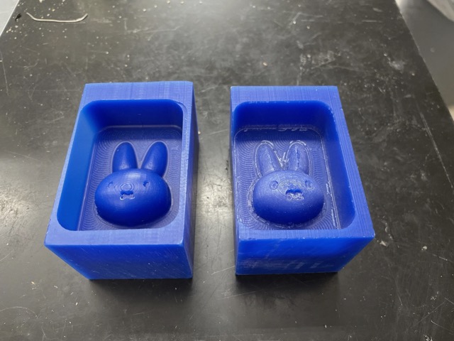
Resin 3D Printed Mold
Another task of this week was to test the Formlabs printer and compare the mold prints between PLA and resin. I made a few modifications to my design in Fusion360 to reduce the amount of ‘cups’ during the print. I saved this file as a .stl.
In Formlabs, I originally selected auto-orient, but that didn’t rotate nor re-orient my design. So instead, I manually rotated my file and automatically added supports.
For the most part, this print turned out fine. However, there was a part of the side that was missing, which dug into the design of my mold. I’m not sure if this was because of the lack of distance between the mold design and the edge of the block, or if it just had a print error.
When I catch you Formlabs, when I catch you…
Milled Wax Mold (Inverse)
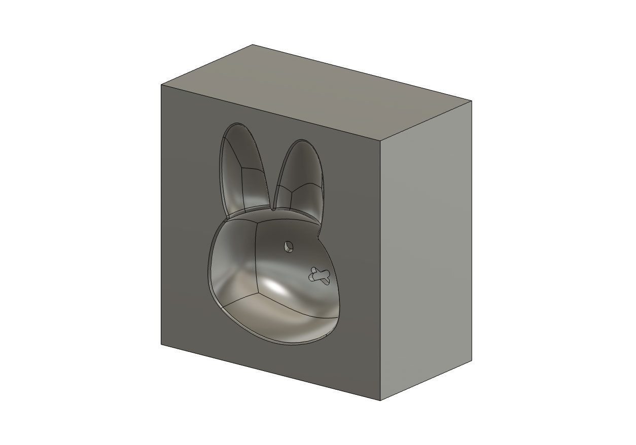
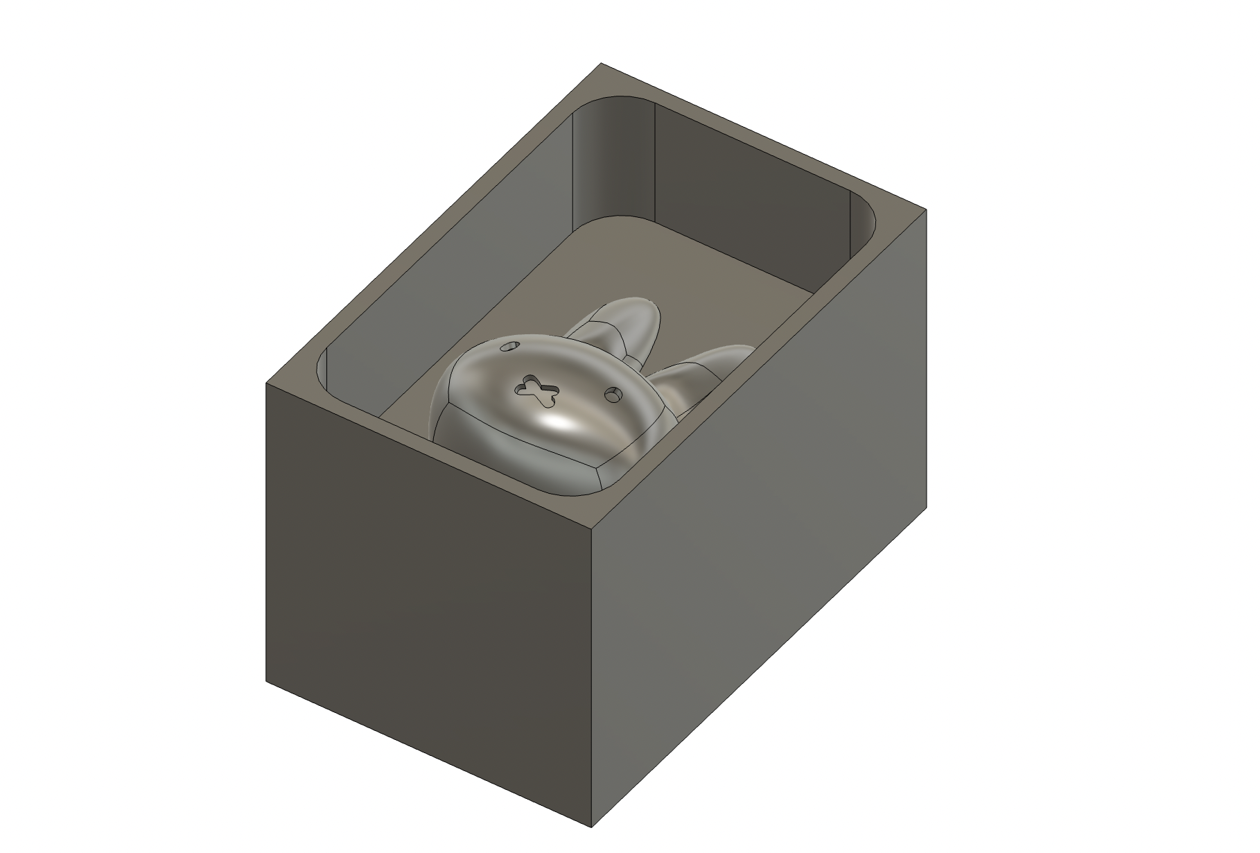
For my milled mold, I wanted to create an inverse mold (subtractive > additive > subtractive). To do this, I used the join operation with the combine tool instead of cut. At this point, I also cut a piece of wax to mill the design in, so I changed the dimensions of the stock to approximately 2” x 3” x 2”. Here is what the updated design looked like:
CAM in Fusion360
I have some minor experience with generating milling toolpaths in Fusion360 from last year, but I was still not fully sure how to work everything. Thankfully, I was able to follow this workflow, which had a general outline of how to work with the Manufacturing workspace, as well as some additional resources. I started by configuring a set-up by going Setup > New Setup.
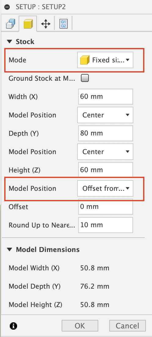
I planned on using the Bantam desktop milling machine, so I selected Bantam Tools Desktop CNC as my machine. Then, under Work Coordinate System, I chose Select Z-axis/plane & Y-axis and selected the top of my stock as the z-axis.
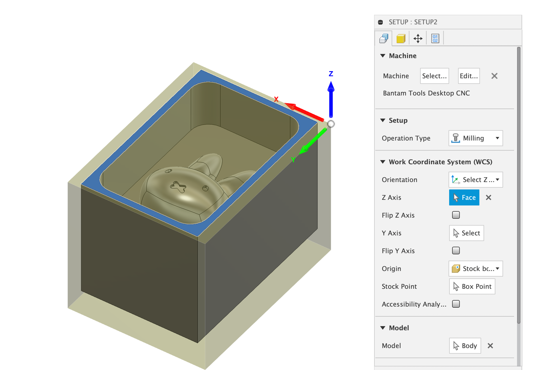
In the stock tab, I changed the mode to fixed-size box, before changing the model position to offset from the top. Lastly, I set the offset to 0.
In the toolbar, under the 3D tab, I chose to first do an adaptive clearing for my roughing. I chose to use the #1 - Ø1/8” flat (1/8” Flat End Mill). I selected this one because it was the biggest bit and will remove the most material in one go. All othermill tools can be found through this library.
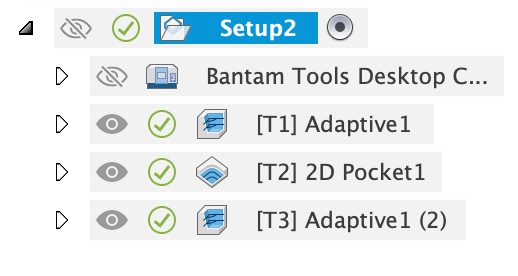
For the cutting feedrate, I referenced this website, which gave an overview of the cutting feed rate, plunge rate, etc. I ended up creating three different toolpaths: 1) 3D adaptive clearing roughing with the 1/8” flat end mill bit 2) 2D pocket roughing with the 1/32” flat end mill bit, and 3) a 3D adaptive clearing finishing with the 1/8” ball end mill bit. For the finishing, I kept running into the issue of the bit colliding with the stock, so I played around with some of the different options and made minor changes to my design (i.e. adjusting the depth of the eyes/mouth). In the end, with the help of my instructor Dr. Taylor, we were able to generate the finishing by duplicating the first adaptive and changing the settings.
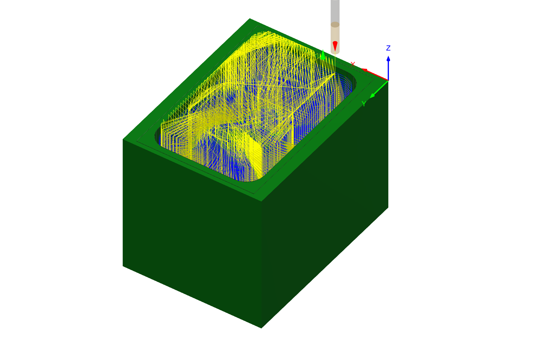
After simulating this a couple of times, I was able to eliminate all collision errors.
One thing to note: all toolpaths had the full check, which indicates the validity of the toolpath, parameters, and in-process stock.
Now, it was time to post-process! To do this, I selected Post Processing under the Action tab of the toolbar.
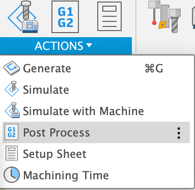
Then, in the dialogue box, I ensured that the post was set to Bantam Tools and that the NC extension was “gcode”.
Note that this will be different based on the model of the milling machine you’re using!
Milling Workflow (Variation)
After going through two iterations of milling, documented below, I modified Dr. Taylor’s workflow with some changes I made.
-
Change Fusion360 workspace to Manufacture
-
Click new setup in setup drop-down menu
-
In the dialogue box, in the setup tab, select machine as
Bantam Tools Desktop CNC -
In the stock tab, change the mode to a
fixed-size box -
Under height, change the model position to
offset from the top -
Change the offset to 0
-
Click ok in the dialogue box to complete the setup
-
In the toolbar, under the 3D tab, select
adaptive clearing; this will differ from person to person, depending on the type of milling job. -
In the dialogue box, in the tool tab, select the tool as “1⁄8’ R1/16” (1⁄8” Ball End Mill)” from the other mill tool library. You will need to install the other mill tool library.
-
Adjust the geometry tab according to your design.
-
Click ok in the dialogue box to complete the pocket cleaning
-
The previous steps can be done for other toolpaths, such as a finish pass with the 1/16” ball end mill.
-
Under your pocket toolpath on the left side of the screen, you can simulate your pocket to see how it is going to work. Under the Info tab of the simulation window, you will see an estimated length of time for your file to be milled.
-
In the Action tab of the toolbar, choose Post Processing (note that this is mainly applicable for one toolpath in the job)
-
Post Process will transform your file into .g-code, which is a computer numerical control (CNC) programming language.
-
Under Post Process, you need to set the Post to Othermill (OtherPlan) or Bantam.
-
Name your file under the Program and make sure the Unit is Millimeters.
-
Load your .g-code into engproj from your computer and then download the file onto an desktop computer.
-
Next, please load your file in the Bantam Tools software.
-
Apply nitto tape or some other form of fixturing onto your material.
-
Use calipers to obtain the x, y, and z material sizes and insert these values into the software accordingly
-
Move your file location to fit the center of your material.
-
Select the tool you’re using under File Setup
-
Similar to the smaller OtherMill desktop milling machines, insert the bit into the collet and tighten with the wrenches
-
Select
mill single filefor each toolpath -
Once the job is over, collect remaining material (if wax), and vacuum all the area around the drill bit.
Iteration 1: Failed
After I applied nitto tape (fixturing) on the bottom of my wax block, I used calipers to measure the x, y, and z measurement. Next, I brought my gcode into the Bantam software. I noticed that the positioning of the design was off based on the software’s reference, and it was only prompting me to select one tool. Assuming it would enable tool changes as it went, I made minor adjustments to the plan offset and ran the milling job. It wasn’t until afterwards that I found two major flaws.
First, despite generating three different toolpaths with different bits, Fusion360 post-processing compressed all of them under a singular g-code, which didn’t prompt tool changes. This meant that the entire job, including the 2D pocket and the finishing were done with the 1/8” flat end mill. Additionally, the plan offset did not turn out as expected, resulting in the bit removing one side of the mold. I originally thought this was an issue with the stock offset (x: 8mm, y: 12mm), but after measuring again, I wasn’t sure what the problem was. For the next iteration, I planned on watching the passes more attentively and adjusting offset settings based on observation.
RIP miffy iteration 1, you’ll be missed..
Iteration 2
Seeing that the toolbar post-process option only generated one g-code for all three toolpaths, I instead generated individual g-codes by right-clicking a toolpath and hitting the post-process selection there. When I imported these into Bantam, they were much more organized, and I could select different bits to use. For my wax, because the first block had been used already, I took a general measurement of its length (~70-80 mm) and used the bandsaw to cut a new block. Afterwards, I used a pair of calipers and inserted the new measurements into Bantam.
My settings were essentially the same, besides the plan offset, which I set to x=-1, y=8.
Roughing with the 1/8” flat end mill bit
When it came time to switch to the 1/32” flat end mill bit, instead of inserting the bit all the way up to the ring, I left more room and lowered the bit down. Initially, when it was fully inserted, I found that the tool installation touch-down wasn’t working (there was a small gap between the tip of the bit and the bed).
Besides that minor adjustment, all of the toolpaths were successful, and there were no major issues.
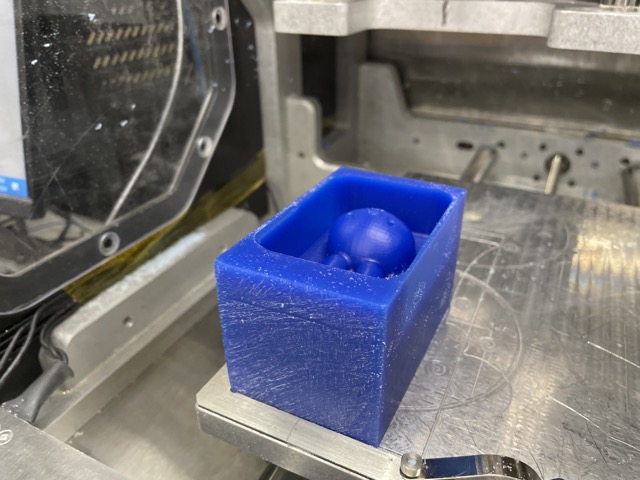
Here is what it looked like taken out:
Comparing the two iterations, I could see the clear difference in stepover and definition when the ball mill bit was used.
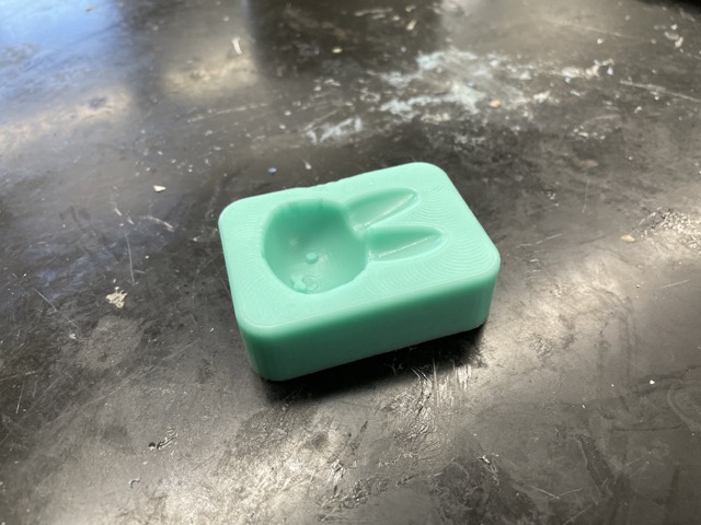
Creating the Mold
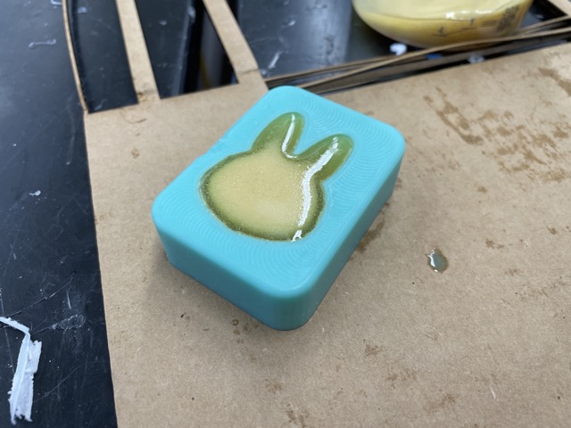
To create the actual mold out of the inverse, I again used the 15 slow moldstar series. I mixed each portion individually, before pouring parts A and B together.
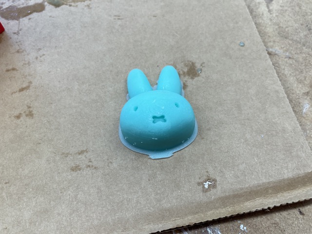
I had a bit of extra, so I poured another silicone miffy with my 3D printed mold :)
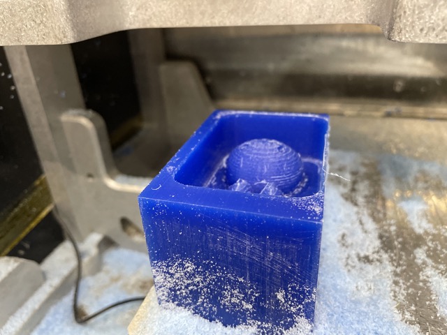
This is what the mold looked like:
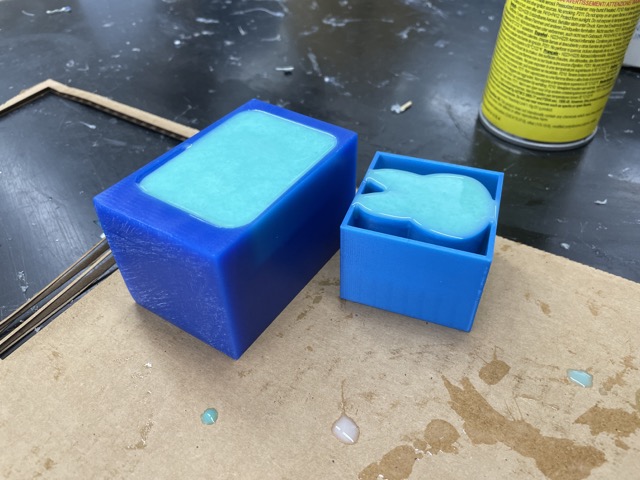
Now, I could do a hard cast! I chose to use Task 8, a quick-curing resin. This similarly had a 1:1 ratio between parts A and B. I simply shook each container, before carefully mixing equal parts together. Because I had worked with this previously, I knew that it heated up quickly, and I had to work quick with it.
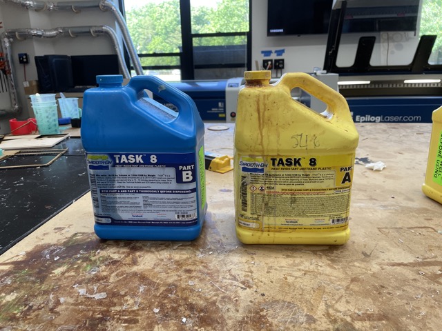
I poured each part until the smallest measurement on the cup (~ 50 mL) and combined them. Then, I slowly poured it into my moldstar mold.
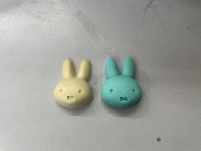
Here is the final soft vs. hard cast! This one turned out pretty good, but I ended up preferring the soft one in the end :)
Group Assignment
For this week’s group assignment, David Vaughn and I compared the safety datasheets for some of the casting materials we used throughout the week, as well as determined the difference between 3D printed molds (SLA) vs. milled molds. You can find our full documentation here.
For my individual contribution, I completed the hard cast using Task 8, subsequently documenting findings, such as the safety hazards.
Reflection
Thank you to Janice Wang for being my main source of inspiration for this week with your cat-sts! I really enjoyed the freedom and creativity that came along with this assignment! Ultimately, I learned more about the manufacturing workspace in Fusion360 and understood what different (cutting feeds, generating toolpaths/g-codes, different types of pockets, etc.) facets of the toolbar meant. On a side note, I’m glad this week allowed me to continue my mass production of miffy themed objects: I’m accumulating fast with my vinyl sticker, PCB board, and the army of miffy casts. Looking forward to wildcard week in particular to continue this journey!! (But for now, its time for electronics)