12. Input Devices
This week, I explored various inputs devices, including RGB color sensors and and visible phototransistors. You can access all of my files here.
Assignment
group assignment:
- probe an input device’s analog levels and digital signals
individual assignment:
- measure something: add a sensor to a microcontroller board that you have designed and read it
Prior Research and Considerations
For my final project, my original intention was to only have my TFT LCD as the input and the output (input = touchscreen, output = timer/potential bitmap design). However, I decided to branch out and try other types of inputs too that could make my desk more ambient/suitable to different environments.
Resources:
Phototransistors
Prior to this week, I wasn’t sure the difference betweeen photodiodes, photoresistors, and phototransistors - to me, they all sounded different but seemed to work all the same. So, before getting started on my circuit and inputs design, I looked into the conceptual definitions of each input.
From this website, I learned that phototransistors are similar to photodiodes in nature as they both produce usable output voltage from the light-generated current. If we think about it in terms of a conventional transistor, the intensity of the light entering the phototransistor can be thought as the amount of current flowing into the base of a normal transistor. Their primary difference is the amount of generated output current (photodiodes typically produce smaller output currents) and their sensitivity levels.
Common Collector Phototransistor Circuit
To begin designing circuits involving phototransistors, I looked into the two main configurations, the common emitter phototransistor circuit and the common collector phototransistor circuit. I ended up creating the common collector phototransistor configuation in my circuit, which contains a resistor connecting the emitter to ground. This configuration generates a a low to high state output (darker setting = higher state output), which I will eventually use to either brighten or dim the neopixels in my pomo-desk.
![]()
There are two main phototransistors I found in the lab: visible and IR. These are just referring to different parts of the electromagnetic spectrum.
RGB Color Sensor
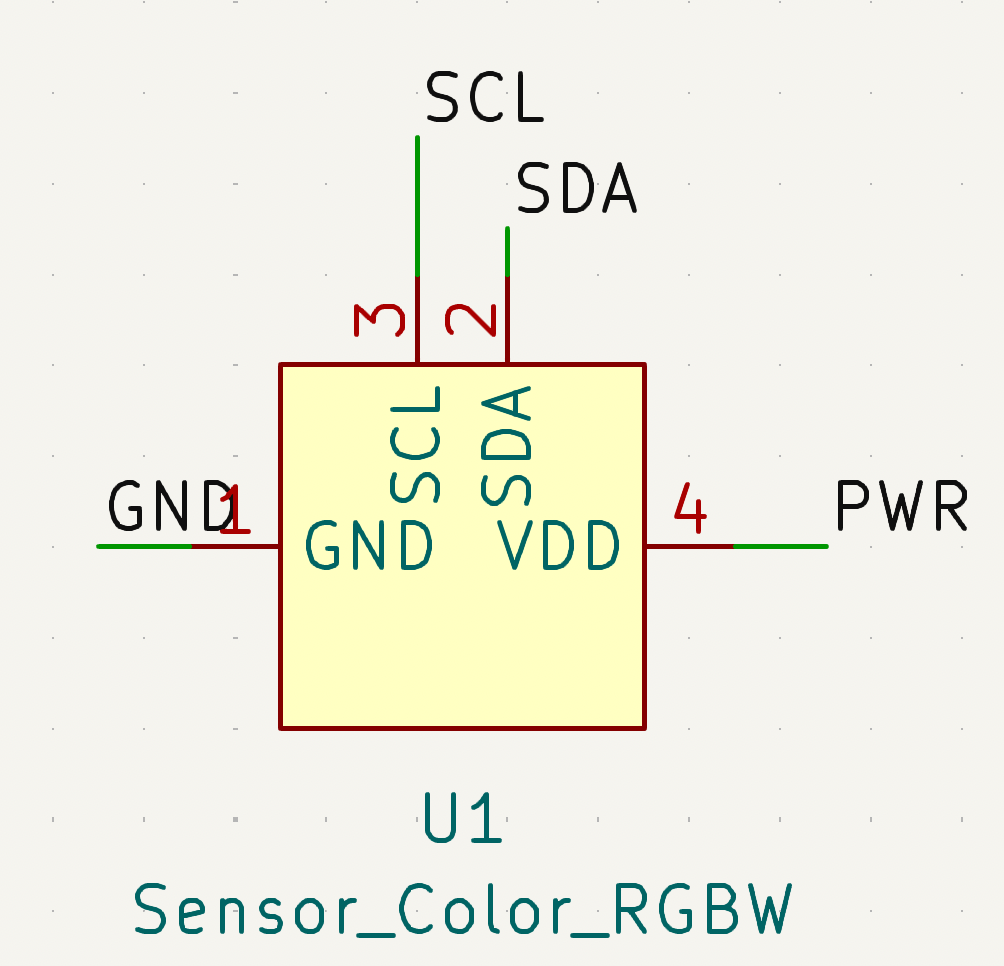
Additionally, I wanted to experiment with an RGB color sensor, a sensor that detects and filters RGB values by receiving light (in other words, it differentiates between the intensity of red, blue and green, respectively). I wanted to see if I could potentially use this in my final project: specifically, I want to adjust the color of the neopixels to fit their surrounding environment.
In terms of the sensor’s smd part, it utilizes an I2C connection, connecting to the microcontroller’s SDA, SCL, PWR (VCC), and GND pins.
Designing an Inputs Board
For my board, I wanted to create an all-in-one inputs board that included all of the potential sensors I would include in my final project (light sensor, color sensor, potentially capacitive touch). I was originally planning on making a board for my touch screen this week, but I decided to do more prototyping with its touch capabilities with the Arduino Uno, and eventually the esp32.
Opening a new schematic editor in KiCad, I created a simple board containing an indicator LED, a phototransistor, a color sensor, a 9 neopixel matrix, and a conn header for additional connections. For this board, instead of using a microcontroller from the attiny series, as I’ve done in previous weeks, I decided to use the RP2040. I was already on a bit of a time crunch this week, so I decided to take an alternative with a board I had more experience in. For more information regarding the board design process, refer to my Electronics Design documentation.
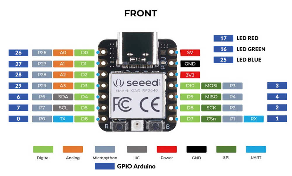
Seeed Xiao RP2040 Pinout
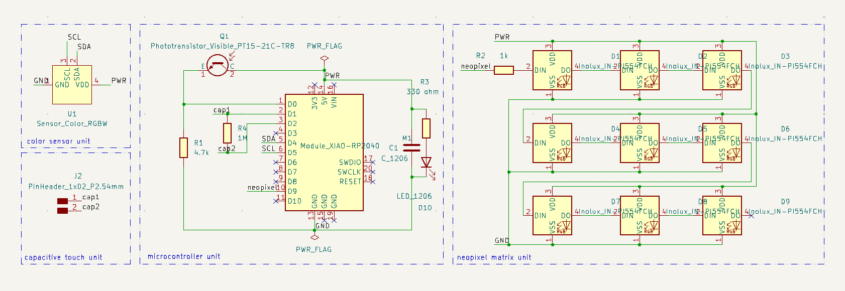
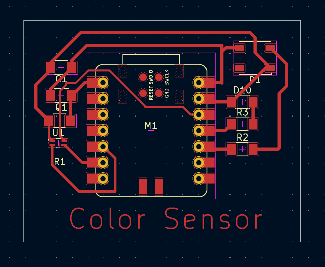
Here is the schematic for my inputs board. I was inspired by Garrett Nelson’s Output Devices board, which similarly contained a neopixel matrix. I referenced his schematics while designing.
I assigned the Fab footprints to the symbols accordingly, configured my design constraints, and began creating routing tracks for my board. I used .5 mm track width for the entire board, except for connections to the color sensor, to which I used .4 mm.
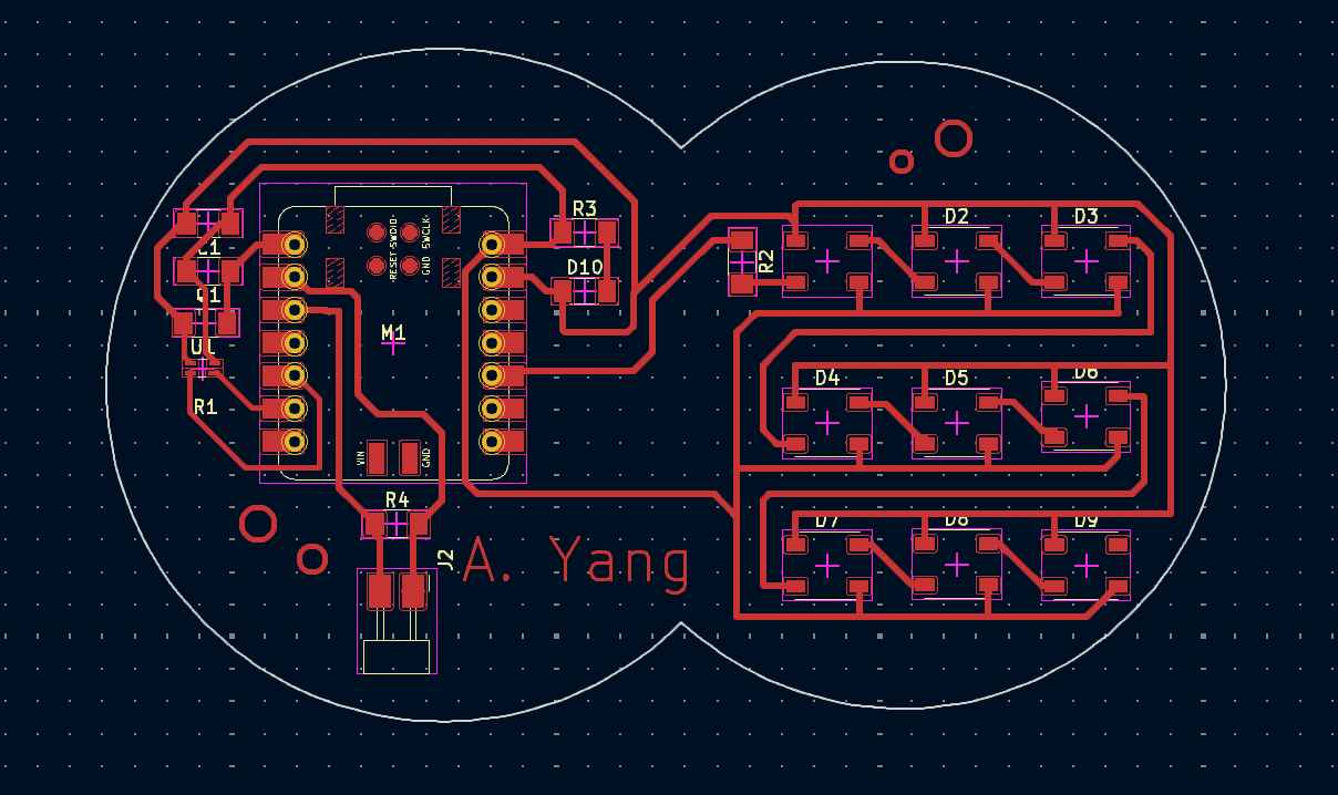
Routing boards is getting a lot easier with practice!
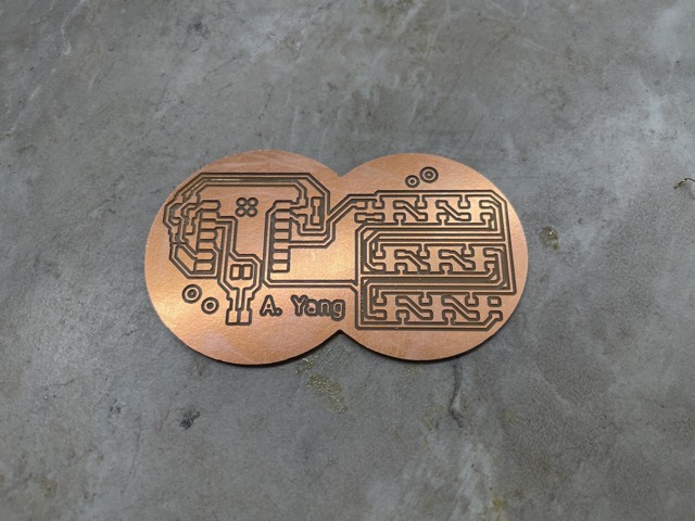
I plotted and saved this board as a GBR file, before bringing it into the Bantam software. For this job, I ended up using the 1/64”, 1/32”, and the 1/100” flat end mill bit. The only issue with the milling process was the Othermill’s z-axis probing: the software kept returning unusual values (>2.5) for the material thickness, so I set it to 1.8mm manually.
Phototransistor
For the phototransistor board, I soldered the following components onto the PCB:
| Component | Quantity |
|---|---|
| Seeed Xiao RP2040 | 1 |
| SMD red LED | 1 |
| 2-pin SMT male header (FTDI) | 1 |
| 499 1206 SMD resistor | 1 |
| 4.7k 1206 SMD resistor | 1 |
| 1k 1206 SMD resistor | 1 |
| 970 nF capacitor (~1uF) | 1 |
| Milled PCB | 1 |
| RGB SMD color sensor | 1 |
| Visible and IR SMD phototransistor | 1 |
| Individual addressable neopixel | 9 |
Note that I similarly applied Kapton tape to the back of the RP2040 to prevent unintentional connections.
One error I noticed was affecting the continuity (i.e. indicator LED was flashing) was a lack of soldering connecting the PCB to the RP2040’s pins. Following Mr. Adam Durrett’s advice, I added more solder to ensure that the electrical connection was secure.
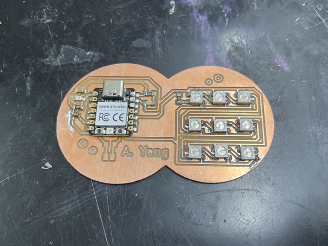
Here is the board after soldering the components, excluding the header pins.
Originally, I wanted to see if the phototransistor was working by printing its values on the serial monitor:
int sensorVal = 0;
void setup()
{
  Serial.begin(9600);
  pinMode(A0, INPUT);
}

void loop(){
  sensorVal = analogRead(A0);
  Serial.println(sensorVal);
  delay(100);

    }
When I placed my finger over the sensor (darker), I noticed that the detected value from the sensor increased from ~100 to ~300. This means that as the received light decreases, the resulting sensor value increases.
Seeing that the sensor was working as intended, I began soldering the neopixels onto the board, noting that the triangle is positioned at the left corner of each pad.
I ran the striptest example under the Adafruit Neopixel library to see if the neopixels worked as intended, setting the D_IN PIN to 4, based on the arduino RP2040 pinout.
![]()
Yay! The neopixels are working!
Once all of the individual components were working, I uploaded the following code in Arduino IDE to test the phototransistor with the neopixels:
// C++ code
//
#include <Adafruit_NeoPixel.h>
#ifdef __AVR__
 #include <avr/power.h> // Required for 16 MHz Adafruit Trinket
#endif

#define LED_PIN    4

// How many NeoPixels are attached to the Arduino?
#define LED_COUNT 9

Adafruit_NeoPixel strip(LED_COUNT, LED_PIN, NEO_GRB + NEO_KHZ800);
int delayval = 100;

int sensorVal = 0;
void setup()
{
  strip.begin();
  Serial.begin(9600);
  pinMode(A0, INPUT); // initializes pin connected to phototransistor
}

void loop(){
  sensorVal = analogRead(A0);
  Serial.println(sensorVal);
  //if (sensorVal>900) {
  strip.setBrightness(sensorVal/4.5);
 // Serial.println("darkish");
   for (int i=0; i<LED_COUNT; i++) {
    strip.setPixelColor(i, strip.Color(240, 66, 96));
    strip.show();
    delay(delayval);
    }

}
Changing the neopixel brightness to sensorVal/-4.5 has the opposite effect (i.e. received light increases, brightness decreases).
When I place my flashlight over the sensor, the neopixels lit up in response. In the future, I may consider exploring other components of similar nature (i.e. photoresistors and photodiodes) that may be more sensitive to light changes.
Color Sensor
When testing my color sensor and running the examples under the VEML6040 library and the TCS34725, I noticed that my serial monitor was either returning a 0 or remained empty when the code was uploaded. I thought this was originally an issue with my serial monitor, but after examining the data sheet of the RGB color sensor, I realized I toasted it by hooking it up to the 5V pin instead of the 3V3. So begins the journey of Angelina changing her board (again)..
To save time and redundancy, I eliminated 8/9 neopixels and kept one for the color sensor testing. Here is what my PCB looked like after modifications:
After soldering, the sensor didn’t appear burnt or changed this time, so I thought I had it working. However, when I uploaded the same example codes, nothing happened again. At this point, it was approaching the end of the week, so I decided to put it off and come back to it later.
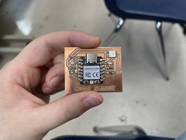
Here’s what the board ended up looking like!
Group Assignment
For this week’s group assignment, we probed an input device’s analog levels and digital signals. You can find our group site here.
David and I split work pretty evenly, as we both probed analog/digital signals with the oscilloscope and the multimeter. Our main struggles consisted of a lack of change in voltage/current, which was our expected outcome. After trying a bunch of times to adjust the brightness, I realized that it may have to do with the program itself, as 5V is supplied to the neopixels regardless (only brightness is adjusted, not the power). Thus, I reprogrammed the neopixels to fade off and on based on received light (mimicking a PWM fading LED).
Reflection
I had a lot of fun and challenges with this week! I got to explore many types of sensors I barely considered before (though perhaps not all of them worked), learn about differences between certain types of sensors, and I have even more ideas now for my final project! This was also a nice way to wind down after the hectic machine week (aka seeing nothing but claw machines for two weeks…). Although I ended up not designing the mother board for my tft lcd, I was still able to prototype with it a little, getting the touch features to work. Excited for weeks to come!!