Week 3 - Computer Controlled Cutting Group Project: Richard, Angelina, Alana
Group members: Richard Shan, Angelina Yang, Alana Duffy.
Assignment
Characterize your lasercutter’s focus, power, speed, rate, kerf, joint clearance and types. Document your work to the group work page and reflect on your individual page what you learned.
Work Distribution
| People | Description |
| Richard, Angelina, Alana | Documentation |
| Richard, Angelina, Alana | Focus test |
| Richard, Angelina | Power, Frequency, Speed test |
| Richard, Angelina | Test cut designs |
| Richard | Kerf test |
| Angelina | Laser cutting definitions |
| Angelina | Joint clearance test |
Laser Cutter Specs
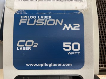
Model: Fusion M2 32 / 40 Laser System (CO2)
Specs:
- 32” x 20” work area
- 75 to 1200 DPI resolution
Defaults for corrugated cardboard:
- Vector: 25% speed, 100% power, 15% frequency
- Raster: 300 DPI, 100% speed, 25% power
Settings for ⅛” wood:
- Vector: 10% frequency, 8% speed, 100% power
- Raster: 300 DPI, 40% speed, and 100% power
Definitions
-
Focus: the focus is the diameter of the emanating laser beam, which is often ¼”. Focal length is the distance between the lens and the material below. Focus lens refers to the series of mirrors that the laser beam is directed through; it ensures high-quality engraving and precise cutting
-
Power: the power is the intensity of energy delivered by a laser beam per second. 100% represents the highest amount of power possible.
-
Speed: the speed is how fast the laser head is moving in the x and y directions; whereas faster speeds lead to short exposure times, slow speeds lead to long exposure times (exposure time = duration a material is exposed to a certain condition)
-
Rate: laser cutting rate is the rate at which the laser cuts the material, expressed in length per unit time. It changes with material type, material thickness, width of cut, etc.
-
Kerf: Kerf is the width of the material removed by the laser beam; it is affected by the intensity of the laser beam, the type/thickness of the material, and the focal length.
-
Joint clearance and types: Joint clearance refers to the intentional gap between different components; similar to the kerf, this enables proper fit during assembly.
Kerf Test
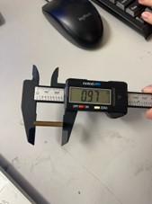
To measure the kerf of the laser, we first cut a square out of cardboard. It was designed to be exactly 1 inch by 1 inch. To measure the kerf, the width of a cut, or the width of a material that is removed by a cutting process, we used calipers to accurately find the dimensions of the cutout. By subtracting the width of the actual square from the theoretical width of 1 inch, we would be able to find the width of the cuts on both sides. After measuring, we found that the actual square was 0.97 inches long. To find the kerf, we divided this value by 2 to represent the width difference on one side of the square.
Kerf = (1 - 0.97) / 2 = 0.015 inches
 |
 |
 |
Frequency, Power, and Speed Test
For our test of power, speed, and frequency, we followed Vincent Zhou, William Zhou, and Elaine Liu’s group project approach as a reference. We created a new file on CorelDraw and drew an array of lines, each of which represented a different combination of speed, frequency, and power. Similarly, we used 33%, 66%, and 100% increments, amounting to 27 different combinations.
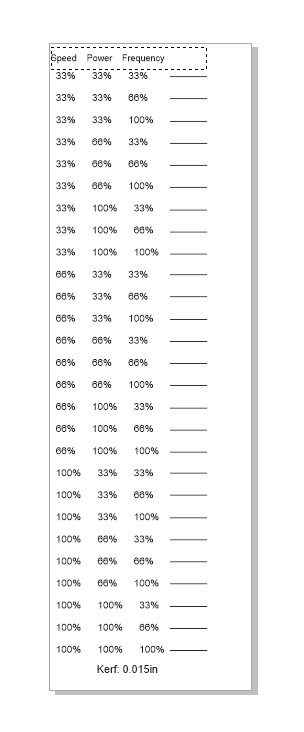
Next, as we prepared to cut, we realized that we wanted to make a slight adjustment to the design: instead of testing out the different combinations on the engraved text (in addition to the test lines), we chose to use the default settings for engraving ¼” wood, and manually test each line.

Trends:
After testing each factor at 33%, 66%, and 100%, we examined the relationship between speed, power, and frequency, using the cut depth and burn residue as primary considerations:
- Speed and cut depth have an inverse relationship; when we compared the 33% speed to the 66% and the 100% (keeping power and frequency constant at 33%), we found that the cut depth was more shallow—indicating that an increase in speed leads to a subsequent decrease in cut depth.
- Power and cut depth are positively correlated: to cut through thicker materials, the laser cutter requires a higher power level.
- General observations: the thinnest cut was at 66% speed, and 33% for power and frequency (the lowest settings on our test); on the other hand, the thickest line had 100% for all elements.
Problems:
- Line was too small
- In Corel Draw, we increased the line size, saved the file, and re-sent it to Epilog.
- We were following ambiguous documentation
- After discussing with each other, we asked Mr. Dubick for help. He told us that frequency cannot be changed for engraving laser cutting, and checked the settings on the medium-sized laser cutter to double-check. Thus, we decided to adapt by changing our laser cutter tests from engrave to vector.
- Couldn’t change frequency value
- As previously mentioned, we switched from our original plan (to characterize our laser cutter’s power, speed, and frequency with engraving tests and comparisons) to vector cutting.
- Epilog Engraver software crashing
- Uncharacteristic of Epilog normally, it was continuously crashing while we were trying to laser cut. We had to close and restart the program multiple times before we could successfully laser cut.
Focus Test
To test how focus impacts a cut, we ran the same job several times with different distances between the laser beam and the material. First, we imported an image from the internet and traced a bitmap (detailed logo). After examining the focus feature on the Epilog, we decided to move the laser beam further away in .05 increments (+.05). We started at 0.0 to use as our benchmark, and we went to +.2.

To change the focus on the laser cutter, we moved the joystick up and down.

We noticed that the engraving became darker and deeper in the wood as the distance grew. The only discrepancy is that the engraving at 0.0 is already pretty dark, but we found that this pattern existed nonetheless.

Joint Clearance Testing
For joint clearance testing, we designed a comb with slot widths from 3.5 mm to 4.0 mm, as well as six identical squares. We did this to determine the ideal slot width for cardboard (note that thickness = approx. 3.8 mm).
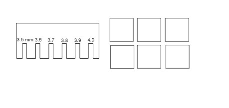
After testing the six different slot widths, we found that 4.0 mm was too wide for the cardboard (fit loosely) and 3.5 mm was too tight (we couldn’t push the square fully up without bending the cardboard). We found that 3.7 and 3.8 mm were the most ideal slot widths.

File Downloads
All of our design files for this project can be downloaded here.