Week 6 - Embedded Programming: Connor, Angelina, and Kabir
This week’s task was to read through a datasheet for our assigned microcontroller and compare it to other architectures. We also had to program our board using a microcontroller development board.
ATTiny412 Datasheet
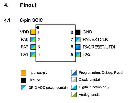
Our assigned board was the ATTiny412. We used this overview to determine the properties of the board.
| Property | Value |
|---|---|
| Architecture | TinyAVR 1-Series |
| Pins | 8 |
| Programmable I/O Lines | 6 |
| Max Frequency | 20 MHz |
| SRAM | 256B |
| Flash | 4KB |
| EEPROM | 128B |
| USARTs (for data transmission) | 1 |
| RTC (Real Time Clocks) | 1 |
| ADC Channels | 6 |
| Window Watchdog | 1 |
Pinout:
SAMD11C Datasheet
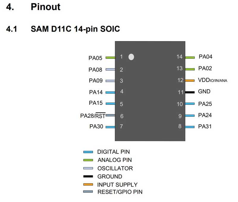
We later tried the SAMD11C board. We used this overview.
| Property | Value |
|---|---|
| Architecture | ARMv6 |
| Pins | 14 |
| Programmable I/O Lines | 12 |
| Max Frequency | 48 MHz |
| SRAM | 4KB |
| Flash | 16KB |
| EEPROM | Can be emulated for 8 different settings |
| SERCOMs (can act as USART, UART, SPI, etc.) | 3 |
| RTC (Real Time Clocks) | 1 |
| ADC Channels | 10 |
| Watchdog Timer | 1 |
Pinout:
Comparison between ATTiny412 and SAMD11C
The SAMD11C seems to be much more customizable considering the amount of I/O lines it has and the ability to configure settings such as EEPROM and the SERCOMs to fit your designated needs. The SAMD11C also has much more memory than the ATTiny412 (regarding Flash, SRAM, and EEPROM), so programs that use more memory can be uploaded successfully. Although not listed in the table above, the SAMD11C had almost all of the features and components that the ATTiny412 had, along with several more of them. Overall, the SAMD11C is much better for larger projects, however, its significantly larger size than the ATTiny412 causes it to need more room. The ATTiny412 seems to be preferable to use for smaller and less complex projects.
Programming Microcontroller Development Board
Milling and Soldering ATTiny412 Board
We obtained our board design file from this Gitlab repo, which was made by Adam Harris.
Next, we milled the board out on copper and had no significant problems during the process.
Here is the components list for the board:
- ATTiny412 chip
- Blue LED
- 499 Ohm Resistor
- 6-pin SMT Header
Once the components were placed on the board, we tested it and all of the connections seemed to work.
Serial UPDI + VCC Module (Connector Piece)
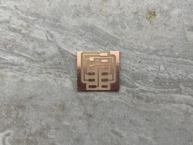
To program to board with the QuenTorres, we also required a UPDI connector board, which was found on the Fab Academy schedule page for this week. Here is what the .png traces look like:


Because there were no pre-made files available, we had to design our own in modsproject.org.
In Mods, we went from Right click > programs > open program > PCB under the othermill list > select .png from files and pulled the traces design. We did this twice, once for the traces (1/64”) and once for the outline (1/32”).

Then, toggling the on/off button next to the files option (auto-save option) and clicking calculate, we finished our design files!

After importing this file into the Bantam software to mill, we kept the same settings as before.
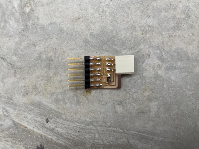
Here is the components list for the board:
- 6-pin SMT male header (FTDI)
- 3-pin SMT female header
- 4.99Ω 1206 resistor
Here is the soldered board:
Programming
Arduino as Programmer
We first created a basic programmer-to-target board using the Arduino Uno board and three female-to-male jumper wires.
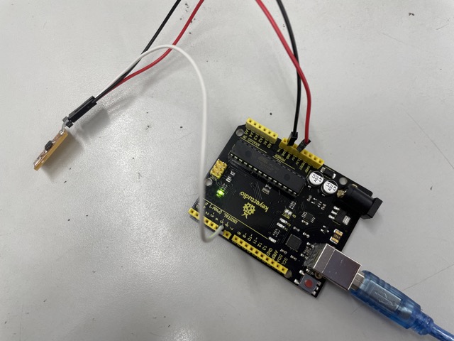
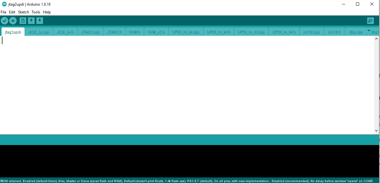
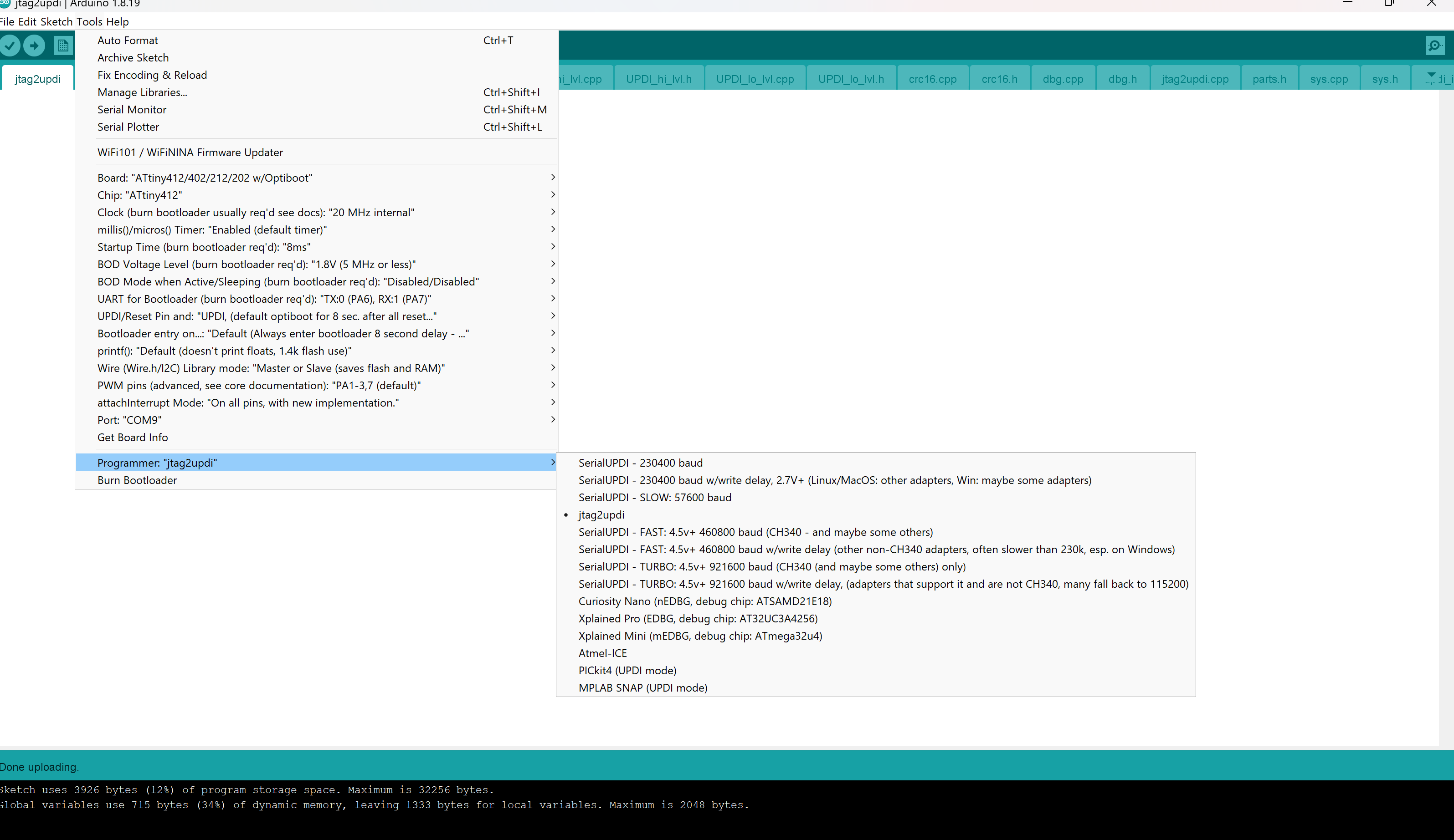
Opening up Arduino IDE, specifically the 1.8.18 version, we uploaded the empty jtag2updi program onto Arduino Uno microcontroller. This ensures that the microcontroller acts as a programmer for the ATtiny.
Next, we installed MegaTinycore, a library that allows us to access the ATtiny series as a board.

Referencing the pinout, we wrote up a simple blink code for pin 4.
int LED = 4;
// the setup function runs once when you press reset or power the board
void setup() {
  // initialize digital pin LED_BUILTIN as an output.
  pinMode(LED, OUTPUT);
}

// the loop function runs over and over again forever
void loop() {
  digitalWrite(LED, HIGH);   // turn the LED on (HIGH is the voltage level)
  delay(1000);                       // wait for a second
  digitalWrite(LED, LOW);    // turn the LED off by making the voltage LOW
  delay(1000);                       // wait for a second
}
Here’s what the board looks like when the code was uploaded:
Using the RP2040
After testing the blink board with the Arduino, we tried the same code with the QuenTorres. This time, we included the UPDI board, connecting it to the target with jumper wires as the pins didn’t line up.
We simply uploaded the same code after plugging in the RP2040.