7. Computer Controlled Machining - Landon, Ryan, Daivd
This is the group documentation site of Landon Broadwell, Ryan Zhou, and David Vaughn for computer controlled machining.
Toolpaths
To measure the toolpaths of the Shopbot Machine that we use, we ran three different profile cuts around the same square vector that was copied and pasted twice. Each profile cut had a different setting for where it cut, being either on the inside or outside edge of the vector or directly on the vector.
Due to material and time constraints, we worked with a different group to expedite the process and save materials. Following our lab’s procedure for the CNC machine found here, we set up the three squares with the aforementioned differing toolpaths and ran the Shopbot. Also, we added tabs to make sure the material didn’t fly out of the bed. The file for this cut can be found here.

After being cut out, we used an oscillating cutting tool to remove the tabs.

This was the final result of this process:
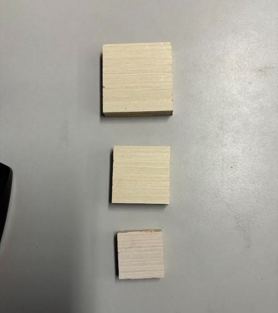
As shown by the image, the inside cut made the smallest square, the cut on the line made a medium-sized square, and the cut on the outside made the largest square. For parts like those used in individual CNC projects, the outside setting is the best, as it eliminates the need to change the design or consider the alterations of the offset. Because of this, it is likely best to always use the outside cut.
Runout
When using a CNC machine and most CAM machines, the tool is not running perfectly cylindrical and is slightly tapered, runout measures how much the bit spins out. When running a ¼” hole with a ¼” drill, there will always be some slight increase in the amount that it cuts out from the material.
We used a dial test indicator, or plunger indicator, to check the runout of the small Desktop milling machine in our lab. Runout depends on the tool, collet, and spindle all together, for it is not just a single aspect that determines the runout. The spindle houses the motor, and bad spindles could have bad bearings
The above video shows that, when the spindle rotates, its base is not perfectly circular. Because of this, the bit will be slightly off center at times. As the video shows, the tool is marked with a number (5, 10, 15) for every 5 large tick marks. Because the runout only goes to the first large tick mark when the spindle is spinned, we can tell that the runout is around one-ten-thousandth of an inch, or ~0.0001”. This is a very low amount of runout, meaning that you will almost never notice inaccuracies while CNCing due to it.
Fixturing
Fixturing is the process of using different methods to hold down the material that is being cut. Different methods include clamps, brads, screws, and more. For our purposes, we use a pneumatic brad gun to shoot brads, which are a type of plastic nail, into the material at different locations. The gun is powered by putting compressed air, made by a separate machine, into the bottom via a tube. In case the brads are caught in the CNC job, they can simply be destroying and sucked up through the ventilation system due to them just being plastic.

Clamps are a more simplistic fixture when CNC, as they just involve moving the two sides together until they compress the material to the bed or whatever other thing is being used.
Materials
The two materials used in our lab were .5” and .75” plywood, but there exist many other types of materials that can be used. Plywood is highly versatile, able to be used for furniture, cabinets, and likely dozens more. Other options include many metals, acryllic, and more. Materials have the capacity to be worked on and applied in many different ways, and they all depend on how the user intends to use them.
Alignment
Alignment in the context of CNC machining is how the machine orients itself internally, particularly with Z, Y, and X coordinates and homing the machine. To home the machine, we type in “C3”, which sets the X and Y coordinates to zero and sets the Z axis to ~6.9in. Homing the X and Y axes allows the machine to properly cut the material in the correct place, and homing the Z axis allows the machine to cut into the material to the correct depth relative to the machine bed.
Safety Training/Issues
Our lab is very focused on our safety while operating tools like the CNC machine, and so we have a complete workflow for the CNC machine that includes beginning/end of day procedures, air cut procedures, and normal job procedures. Before and while doing our assignments for this week, we reviewed this workflow extensively and followed it closely while cutting out the parts for our assignments. In addition to this, we also followed all of the standard safety procedures in our lab, such as wearing safety glasses and earmuffs while operating the CNC machine. The only major issue while operating the CNC machine is to make sure not to get your clothes/hair stuck on the spindle while it moves, which is why we are advised to take off jackets and tie back hair while using the machine.