4. Embedded programming
Things I should do different this week.
- Set my apple device to take photo's in JPEF instead of HEIC
- Use markdown better
- Write down what's neccesary
- Spiral development
- time management
- Make screen recordings in mp4 instead of MOV. Oops, quicktime can't.
- cmd pallete > markdown open preview to the side. for better overview.
Assignment
Group assignment
- Compare the performance and development workflows for other architectures
- Document your work to the group work page and reflect on your individual page what you learned
Individual assignment
- Browse through the datasheet for your microcontroller
- Program a microcontroller development board to interact and communicate
Intro
This week we will program, design and build an embedded board. It’s very much about experimenting this week! I’ll start with cc++ or python.
Cheat sheet for this week
- chip: is small, black(sometimes white) and has little metal legs. A chip is the umbrella term for a lot of thing.A micro prosessor or micro controller both can be chips.
- Arduino: C with labraries
- micro poroccesors: data in data out (simple)
- micro controllers: is a micro proccesor with added feature. Added features are peripherals. Peripherals are used to comunicate with the outside world.
- Xiao: means tiny but powerful
- bootloader:
- IDE: this is an interface to write, compile and upload code in.
- Digital pin: on/off, 0/1, Low/High
- Analog pin: 0-5 V, 0-1045
- Pulse with modilation: you can dim a LED with a digital output.
- Compile: converting code
- CPU: A Central Processing Unit or CPU is electronic machinery that carries out instructions from programs that allows a computer or other device to perform its tasks.
- Clock speed: The clock speed measures the number of cycles your CPU executes per second, measured in GHz (gigahertz). In this case, a “cycle” is the basic unit that measures a CPU’s speed. During each cycle, billions of transistors within the processor open and close .
Storage
- Dram: stores data but slowely
- fuse: memory
- SRAM: (static RAM) is a type of random access memory (RAM) that retains data bits in its memory as long as power is being supplied.
- Cache: Temporary storage area that the computer’s processor can retrieve data from easily.
- ROM: (read only memory) retains its memory even after the computer is turned off
- FLASH: Is a better version of ROM. Bigger memory but harder to program
-
EEPROM: (e e programmable read only file) a read-only memory whose contents can be erased and reprogrammed using a pulsed voltage.
-
AnalogRead
- AnalogWrite
- DigitalRead
- DigitalWrite
Pieters page is also good for info
Python or C
Before we started with our microcontrollers I wanted to know which options there are in communicating with our controllers.
With our class we discussed which coding language we should use. We considered C and Pyton. I found this metrics online that gives a pretty good comparison between C and Python.
| Metrices | C | Python |
|---|---|---|
| Introduction | C is a general-purpose, procedural computer programming language. | Python is an interpreted, high-level, general-purpose programming language. |
| Speed | Compiled programs execute faster as compared to interpreted programs. | Interpreted programs execute slower as compared to compiled programs. |
| Usage | Program syntax is harder than Python. | It is easier to write a code in Python as the number of lines is less comparatively. |
| Declaration of variables | In C, the type of a variable must be declared when it is created, and only values of that type must be assigned to it. | There is no need to declare the type of variable. Variables are untyped in Python. A given variable can be stuck on values of different types at different times during the program execution |
| Error Debugging | In C, error debugging is difficult as it is a compiler dependent language. This means that it takes the entire source code, compiles it and then shows all the errors. | Error debugging is simple. This means it takes only one in instruction at a time and compiles and executes simultaneously. Errors are shown instantly and the execution is stopped, at that instruction. |
| Function renaming mechanism | C does not support function renaming mechanism. This means the same function cannot be used by two different names. | Supports function renaming mechanism i.e, the same function can be used by two different names. |
| Complexity | The syntax of a C program is harder than Python. | Syntax of Python programs is easy to learn, write and read. |
| Memory-management | In C, the Programmer has to do memory management on their own. | Python uses an automatic garbage collector for memory management. |
| Applications | C is generally used for hardware related applications. | Python is a General-Purpose programming language. |
| Built-in functions | C has a limited number of built-in functions. | Python has a large library of built-in functions. |
| Implementing Data Structures | Implementing data structures requires its functions to be explicitly implemented | Gives ease of implementing data structures with built-in insert, append functions. |
| Pointers | Pointers are available in C. | No pointers functionality available in Python. |
Conclusion
Since I’m a newbie to coding languages I found it hard to practically understand the differences between the languages. It seems Python is easier to learn and has a really big ecosystem that makes it easy to expand your skills. But since I have little experience with Arduino and Arduino has a big library database and lots of tutorials and examples, especially with hardware projects - which I’m interested in. I decided to choose for C working in Arduino because I have limited time and the projects that I’ve done were fairly easy with Arduino.
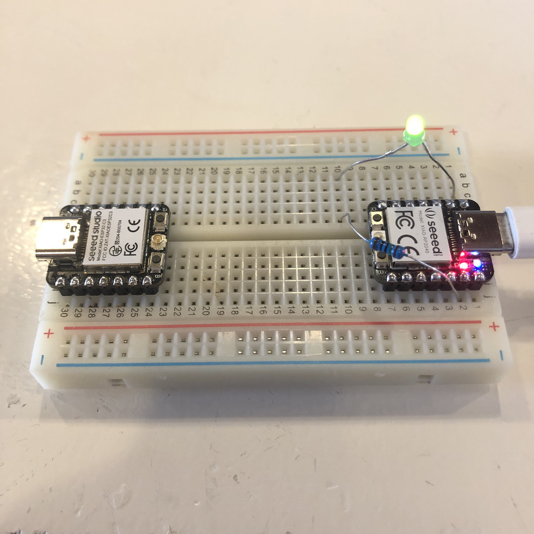
Program a microcontroller development board to interact and communicate
Connecting the XIAO ESP32 and RP2040
1: Hardware setup
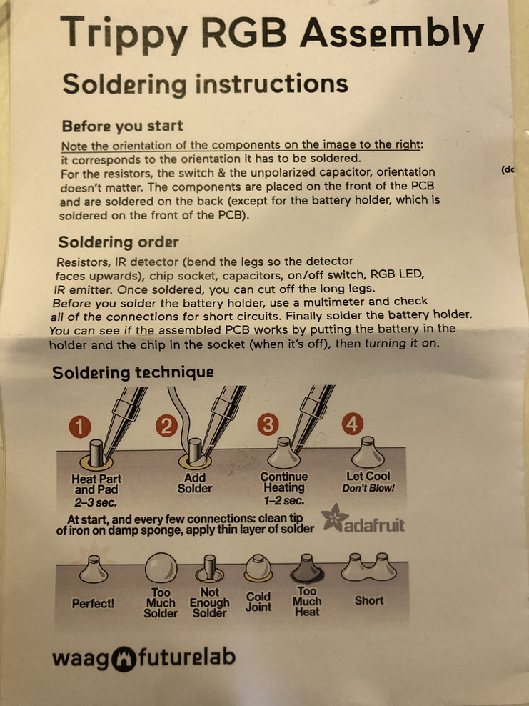
Soldering pins to the chips so we can connect and test them.

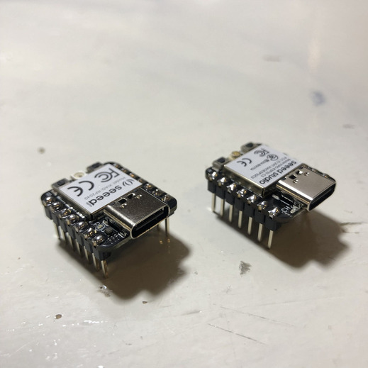
I have some solder experience but due to the following image I know I did some stuff wrong for a while.
2: Software setup
The following links explains all the steps that you have to take. I you read and do exactly what it tells you to do it’s really simple.
Seeed Studio XIAO RP2040 with Arduino
Seeed Studio XIAO ESP32C3 with Arduino
To interact and communicate with my microcontroller development I need to install an IDE and upload the bootloaders for the chips I’ll use the Arduino IDE that I arleady had installed.
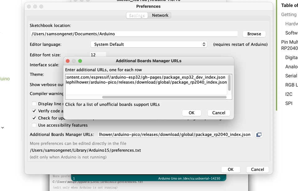
One thing you should keep in mind when you install both of the chips and want to run both of them.
Make sure you click on the folder file icon so you can upload the RP2040 and the ESP32 link otherwise you won’t see both of them in your board menu.
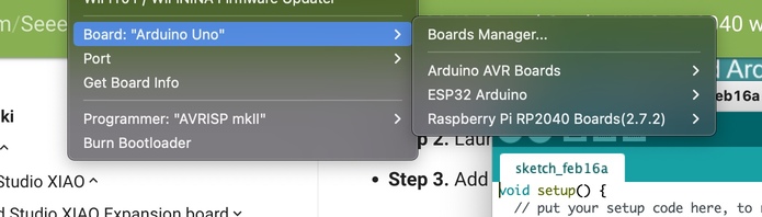
You should see the following boards.
Now I’ll try to get my LED working but unfortunately I get the following error.
D10 was not declared in this scope.
This means that the code is unable to understand the instructions given in the arduino code. Hahaha, very usefull..........

I selected the wrong board.... there are multiple ESP boards. Make sure you select the XIAO version.
Both of my boards are working now with the following code.


Performance and development workflows for architectures
Compare the performance and development workflows for other architectures. For this weeks tests we’ll use the following boards.
- Xiao-ESP32-C3
- Xiao-RP2040
- Arduino UNO
- ATtiny84
What’s an architecture?
- Family of chips. The family of chips have the same range of features.
What are performance and development workflows when we talk about chips?
- The performance of a chip are for example the features of a chip, so the option that are connected to the pins. The calculation speed.
Performance
How can we test the difference between the performances of a chip?
- Compare the different features of the chip
- Calculation - How long does it take to solve an math sum
- How long does is take to switch between high and low. Check in the data sheet.
Compare features
Compare the different features of the chip
Xiao-ESP32-C3 feature list
Xiao-ESP32-C3 data sheet
Arduino uno datat sheet
| Features | XIAO ESP32-C3 | Arduino UNO | XIAO RP2040 |
|---|---|---|---|
| CPU | 32bit RISC-V singlecore processor that operates at up to 160 MHz | AVR CPU at up to 16 MHz | dual-core ARM Cortex M0+ |
| CLock speed | 160 MHz | 16 MHz | 133 MHz |
| word size | 32-bit | 8-bit | 32-bit |
| Storage | 400 KB of SRAM (16 KB for cache) and 384 KB of ROM on the chip | 32KB flash, 2KB SRAM, 1KB EEPROM | 264KB SRAM 2MB onboard Flash |
| I/O pins | 11 digital, 4 Analog | 14 digital, 6 analog | 11 digital, 4 Analog |
| Power | 5v, 3,3v | 5v, 3,3v | 5v, 3,3v |
| Dimensions | 21 x 17.5mm | 53.4 x 68.6 mm | 21 x 17.5mm |
| Bluetooth | yes | no | no |
| WiFi | yes | no | no |
| How to program | usbc cable | usbc cable | usbc cable |
Conclusion
I want to use bluetooth or wifi for my porjects. I need 4 digital and 4 analog pins and would be nice to use something small. The esp32-c3 has everything I need how ever I’m also iterested in the dual-core processer from the rp2040.
Calculation test
Bas helped us to develop an equation dat can meausure the duration of solving the sum.
Explanation of the functions used in Arduino.
- int (integer): Integers are your primary data-type for number storage. It means a round number.
- float: The float is one of the most important Arduino data type as it can store decimal numbers. This data type is for floating-point numbers which are numbers with a decimal point.
- double: While on several platforms, double has more precision than
- float. However, on most Arduino boards (Uno and many other ATmega boards), double has the same size as float. Arduino Due is an exception, wherein double has a size of 8 bytes (compared to 4 bytes of float).
- void setup: The void setup is a function created at the beginning of the program, between the initialization of the variable and the void loop. The void setup contains the initialization of the components such as an input or an output of the Arduino card, an initialization of the serial monitor.
- void loop: Code within Void loops functions repeat consecutively until Arduino is turned off. Whatever we write inside these curly brasses will run again and again.
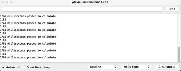
We uploaded the following code to the different boards. And printed the outcome in the serial.

XIAO-RP2040
for the XIAO-RP2040 the serial calculated 1761 milliseconds
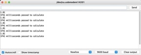
XIAO-RP2040
for the XIAO-RP2040 the serial calculated 3741 milliseconds
Arduino UNO
When I compile and upload the exact same code to my arduino as I did to the esp32 and the rp2030 it won’t work.

Why? My Arduino chip has an 8 bit chip and the other chips are 32 bits.
The Arduino chip has too few bits to calculate the sum that I coded. It should work if we replace the “int” between the brackets by the following code uint32_t
For the arduino UNO with a ATmega328P micro controller the serial calculated 13537 milliseconds
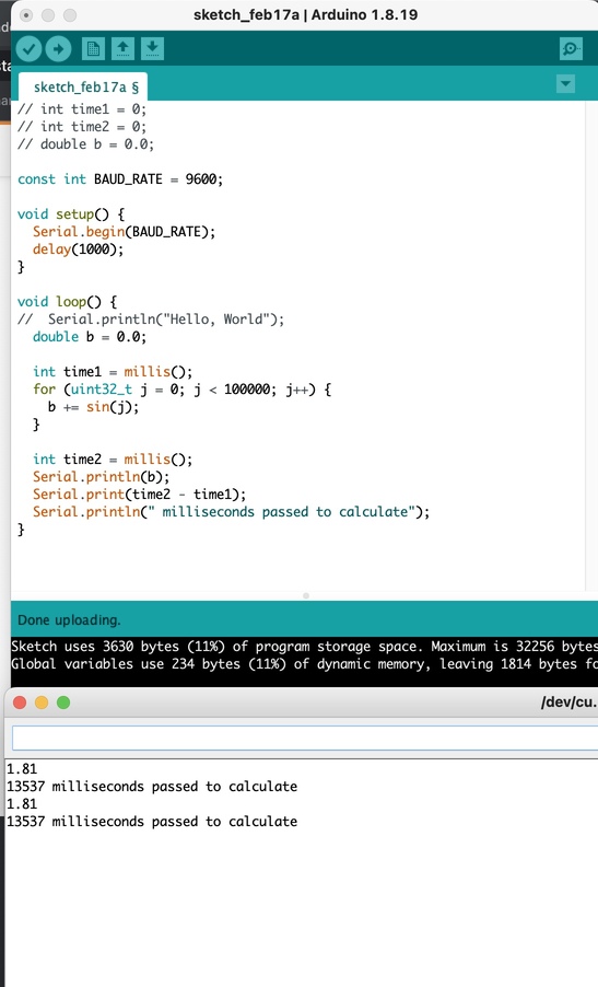
- XIAO-RP2040 = 1761 milliseconds
- XIAO-ESP32-C3 = 3741 milliseconds
- Arduino = 13537 milliseconds
Development workflow
Development workflow
- Compiling test
- Arduino IDE
- Platform IO - plugin for visual studio code
- Micro Python Thonny (Pieter)
Workflow Arduino IDE
Arduino IDE
- Coding
1. Verify: Compile and verify code.
2. Upload: Uploads code (sketch) to the
board.
3. New: Opens new sketch window.
4. Open: Open previously saved sketch.
5. Save: Save current sketch.
6. Serial Monitor: Opens window to display
serial information transmitted by board.
7. Code Area: Type code here.
8. Messages: Displays messages like Synatx
Errors or any other errors with the code.
9. Text Console: Show complete error
message.
10. Board and Serial Port: Displays the name
of the board currently connected to the
computer and the port number.
To download the Arduino IDE software visit:
https://www.arduino.cc/en/Main/Software
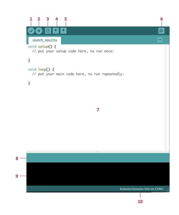
The Arduino IDE is super simplistic in its design and I think also in its function.
Workflow Platform IO
I can spend time to show how Platform IO works with making screenshots and explain it step by step. But I think it would be a waste of time after I watched the following tutorial. It explains most of the possibilities and shows the workflow step by step.
Conclusion
Platform IO has a lot of possibilies and I read a lot of good stuff about this IDE. From a programmer perspective I can imagine this IDE is great since it way more options then the Arduino IDE. But since I’m no programmer I can say without shame that platform IO looks unnecessary features. The IDE looks complicated there’s a lot of stuff hapening in my screen I like the simple arduino IDE there’s already happening loads of stuff when I’m writing code that I don’t know much off. So for now I’ll stay with Arduino and later when I’m a legit nerd I’ll may swap to platform IO.
Compiling test
To check which IDE is faster I’ll compile and upload the same code with Arduino IDE and Platform IO IDE.
Arduino IDE
PLatform IO
It seems that PLatform IO is way faster.
Datasheets
Selecting a microcontroller
Before I’ll dive into a datasheet I thought it would be a good idea to question myself which controller would be suitable for my final project. Datasheets are looooooooooooong so a view focuspoints might would come in handy. The following link shows 10 steps that you can follow when choosing a micro controller.
I’m new in chipworld so a lot of things are new to me. I’ll give it shot.
Step 1: Make a list of required hardware interfaces
For my project I need the following periphirals and hardware.
- 4 servo’s MG996R
- 2 stepper NEMA17
- 2 A4988 stepper motor driver
- Joystick
- Bluetooth
- external powersupply
- usb
MG996R Servo datasheet
NEMA17 datasheet
Joystick datasheet
I chose to limit myself to the pin configuration of the above named datasheets. The psycal specfication I’ll worry about later.
MG996R
| pin No. | Pin name | Description | output |
|---|---|---|---|
| 1 | PWM | pulse with modulation | PWM digital |
| 2 | VCC | posstive supply terminal of module | VCC |
| 3 | GND | ground terminal of module | GND |
NEMA17
The wires of the stepper motor refer to the coils. De stepper driver control the power on the coils.
2 A4988 neccesary pins named
| pin No. | Pin name | Description | output |
|---|---|---|---|
| 1 | STEP | amount of steps | digital pwm |
| 2 | DIR | direction | digital |
| 3 | VVD | possitive supply terminal of module | VCC |
| 4 | GND | ground terminal of module | GND |
Joystick
| pin No. | Pin name | Description | output |
|---|---|---|---|
| 1 | gnd | ground terminal of module | GND |
| 2 | +5V | possitive supply terminal of module | VCC |
| 3 | VRx | Voltage Proportional to X axis | analog |
| 4 | VRy | Voltage Proportional to Y axis | Analog |
| 5 | SW | Switch | HIGH/LOW = digital? |
What do I want from the micro controller?
- 8 digital PWM
- 2 analog
- bluetooth
- usb
There’re mores things that I should take in account, but I’m running out of time.
Datasheet ESP32-C3

Henk told us that some datasheets have a 1000 pages with beautifull (probably incomprehensible for me) information to tell us. This data sheet is 40 pages so I think I made a good choise.
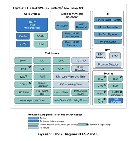
‘’ESP32-C3 series of SoCs is an ultra-low-power and highly-integrated MCU-based solution that supports 2.4 GHz Wi-Fi and Bluetooth® Low Energy (Bluetooth LE). The block diagram of ESP32-C3 is shown below.’‘
This is the first sentence of the datasheet. I recognice some words but understanding is something different. I hope the rest of the document will be a little bit more clear for me.
Unfortunately it becomes way more difficult.
I’ll skip through the document and highlight the things that I think, are most important.
Page 2
Block diagram/product overview. Here you see the coresytem, the peripherals, the wireless connections, the RF (radiosignals), the RTC (clocktime) and the sercurity.
Page 3
Here you see see an overview of all the features the microcontroller has. This comes in handy when you want to check if the controller has what you need.
Page 10
On page 10 you an overview of the pin layout. This is super important. The pins names are abbreviated.
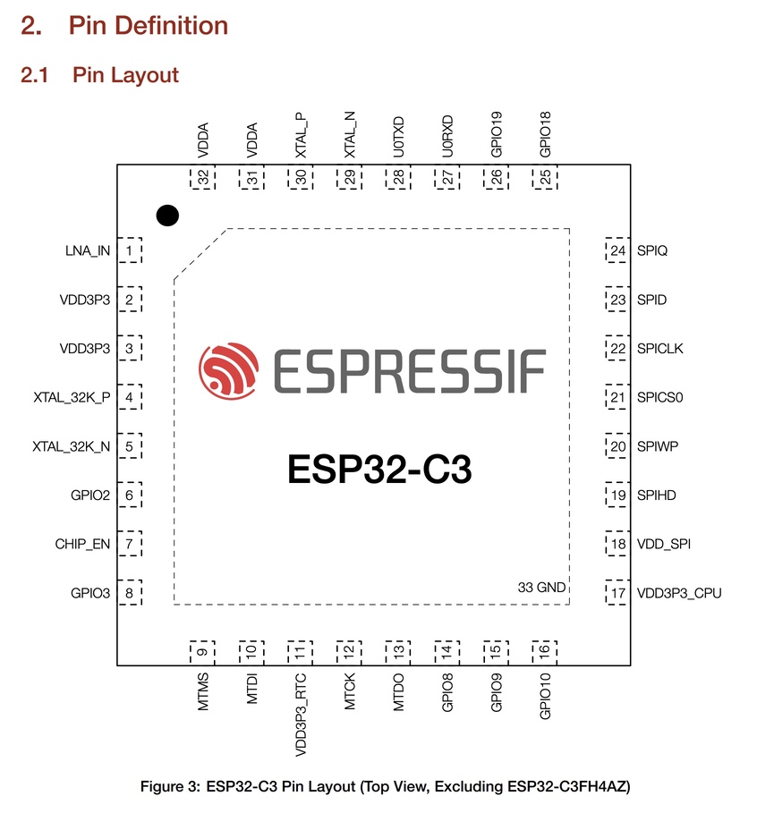
I was looking at the amount of pins and then I counted a bit more… Oops. Mistake. This is a total different data sheet. THis is the datasheet of the espressif ESP32-C3FA4AZ..........
Lets start over.
Datasheet seeed XIAO-RP2040
Shit..... This datasheet isn’t 40 pages but has 646 pages. Huh this pin layout looks the same as the previous one. Haha. I was looking at the correct datasheet though.
I was confused because the pin layout is not in line with my board. But we’re talking about the chip now and not about the microcontroller.
page 10
Almost all of the abbreviations are unknown to me. I’ll research the first 10 of these to see what’s up.
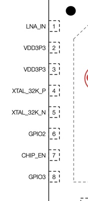
LNA_IN means.. hmm interesting.

LNA: A low noise amplifier (LNA) amplifies a very low-power signal without significantly degrading its signal-to-noise ratio.
VDD: Voltage Drain Drain. It is the drain supply in semiconductors. The operating voltage.
VCC: is the supply voltage of the circuit
XTAL: stands for external oscillator. a periodic fluctuation between two things based on changes in energy.
GPIO: A general-purpose input/output (GPIO) is an uncommitted digital signal pin on an integrated circuit or electronic circuit.
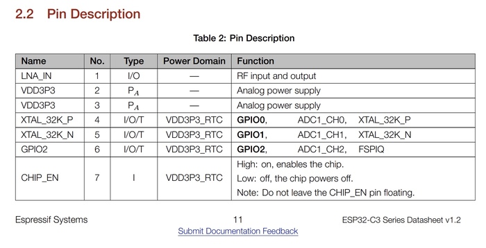
page 11/12
Here you see the Pin discription. You see the number of pins, the type, the power domain and the functions.
page 17
The functional discription starts here. Most important function:
CPU and memory
System clocks
Analog peripherals
Digital perihperals
Radio and WI-FI
BLuetooth
Low power management
Timers
Cryptographic Hardware Accelerators
Physical Security Features
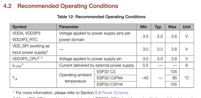
Page 31
Electrical Characteristics
Page 41
Package information

Conclusion
Can I use the ESP32-C3 for my final project?
What I want:
- 8 digital PWM
- 2 analog
- bluetooth
- usb
Instead of checking the data sheet. I used the folowing link.
Really clear pinlayout
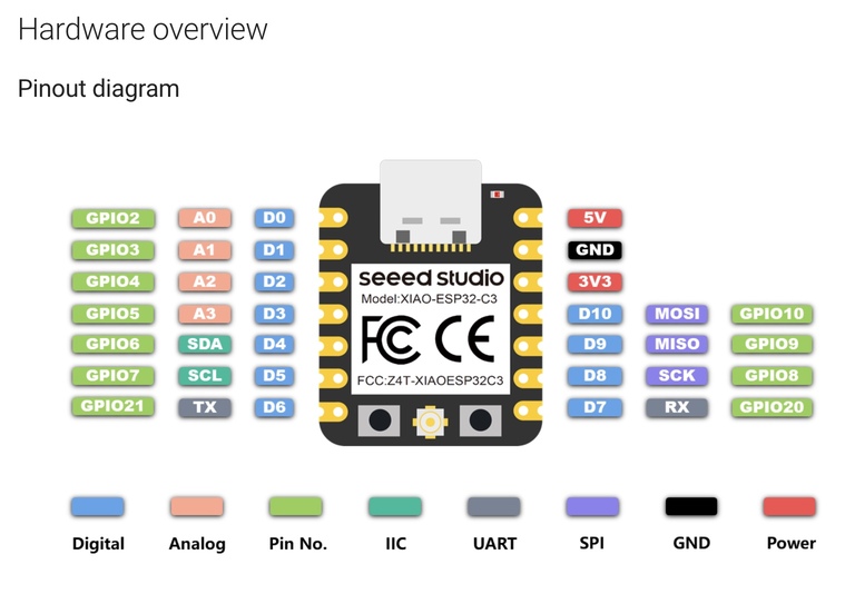
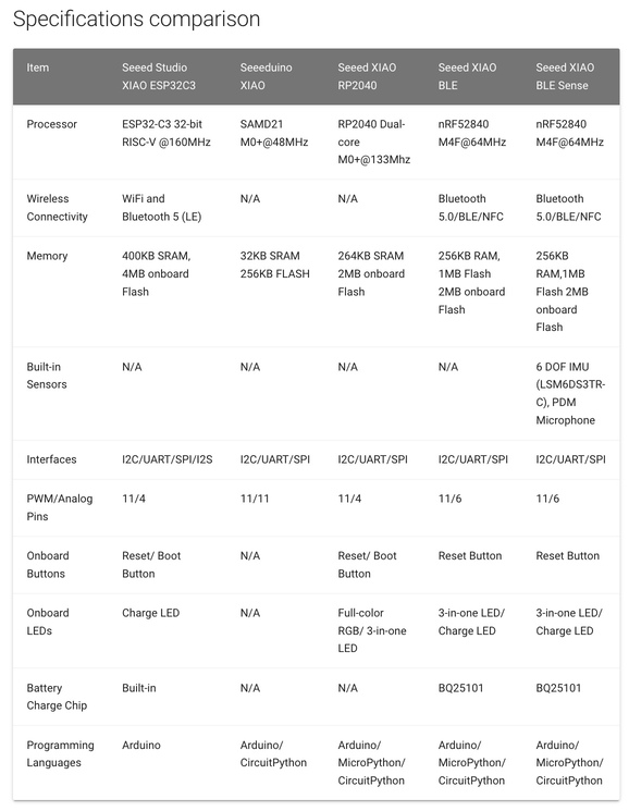
Specification comparison. The ESP is programmable in arduino and in micro python. The amount of digital and analog pins. It has bluetooth. So yes I can use this form my final project.
Testing LDR, FADE, Fade up and drop, Button
LDR: light-dependent resistor
#define LDRpin D0 // pin where we connected the LDR and the 10K resistor

int LDRValue = 0;     // result of reading the analog pin

void setup() {
  Serial.begin(9600); // sets serial port for communication
}

void loop() {
  LDRValue = analogRead(LDRpin); // read the value from the LDR
  Serial.println(LDRValue);      // print the value to the serial port
  delay(100);                    // wait a little
}
Connect 1 ldr leg to 5V, the other to D0 and through 10K resistor to GND.
See serial and plotter for values!
How do I know which resistor is 10K? link
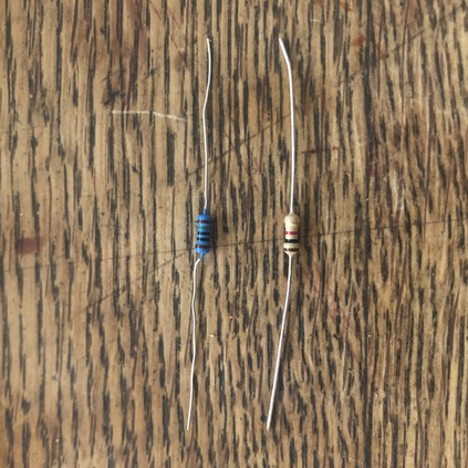
I read a value that’s higher then 1023 which is weird because I’m using a Arduino uno. The uno has an atmega chip with a 10 bit resolution. That would mean that de analog pin would read a value between 0 - 1023 (2^10 = 1024). I think I’ve been doing something wrong here.
Fade up and drop
Here you see that instead of using a 10 bit resolution it’s more common to use a 8 bit resolution ( 2^8 = 256) to represent the intensity of level of brightness.

int led = D8;           // the PWM pin the LED is attached to
int brightness = 0;    // how bright the LED is
int fadeAmount = 1;   // how many points to fade the LED by

// the setup routine runs once when you press reset:
void setup() {
  // declare pin 9 to be an output:
  pinMode(led, OUTPUT);
  Serial.begin(9600);
}

// the loop routine runs over and over again forever:
void loop() {
  // set the brightness of pin 9:
  analogWrite(led, brightness);

  // change the brightness for next time through the loop:
  brightness = brightness + fadeAmount;

  // reverse the direction of the fading at the ends of the fade:
  if (brightness >= 255) {
    brightness = 0 ;
    }
  // wait for 30 milliseconds to see the dimming effect
  Serial.println(brightness);
  delay(5);
}
Joystick
For my final project. I want to control servo’s with a joystick. See final project for code in action.
#include <Servo.h>

Servo servo1;
Servo servo2;

int joyX = 0;
int joyY = 1;
int joyVal;
int dit = 50;

void setup() {
  // put your setup code here, to run once:
servo1.attach(9);
servo2.attach(10);

}

void loop() {
  // put your main code here, to run repeatedly:
joyVal = analogRead(joyX);
joyVal = map (joyVal, 0, 1023, 0, 180);
servo1.write(joyVal);

joyVal = analogRead (joyY);
joyVal = map (joyVal, 0, 1023, 0, 180);
servo2.write (joyVal);
delay(dit);
}