Final project
Octo
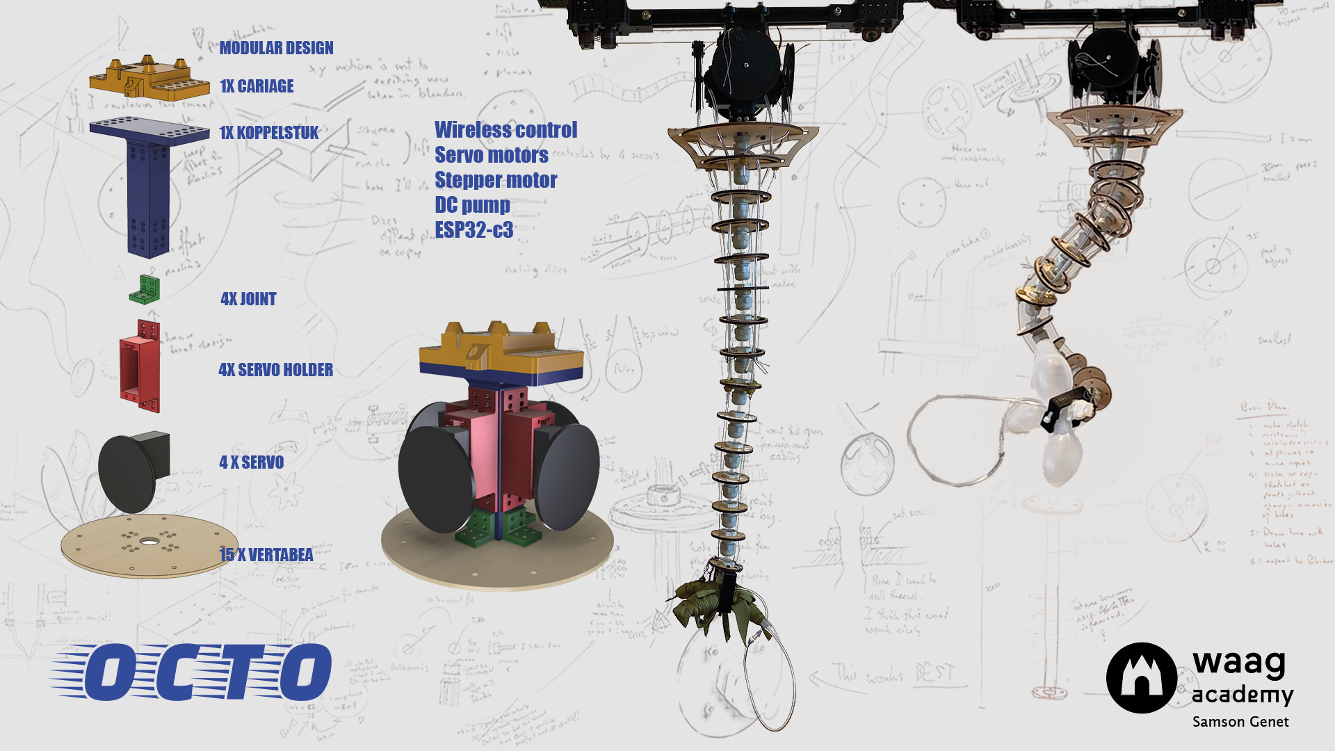
Octo is a modular controllable octopus arm on a linear axes with an inflatable gripper
On this page I’ll explain my research about Octo. Octo is never finished. If you have any suggestions on how to inprove the model please let me know.
Intro
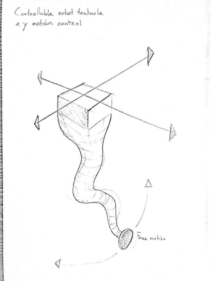
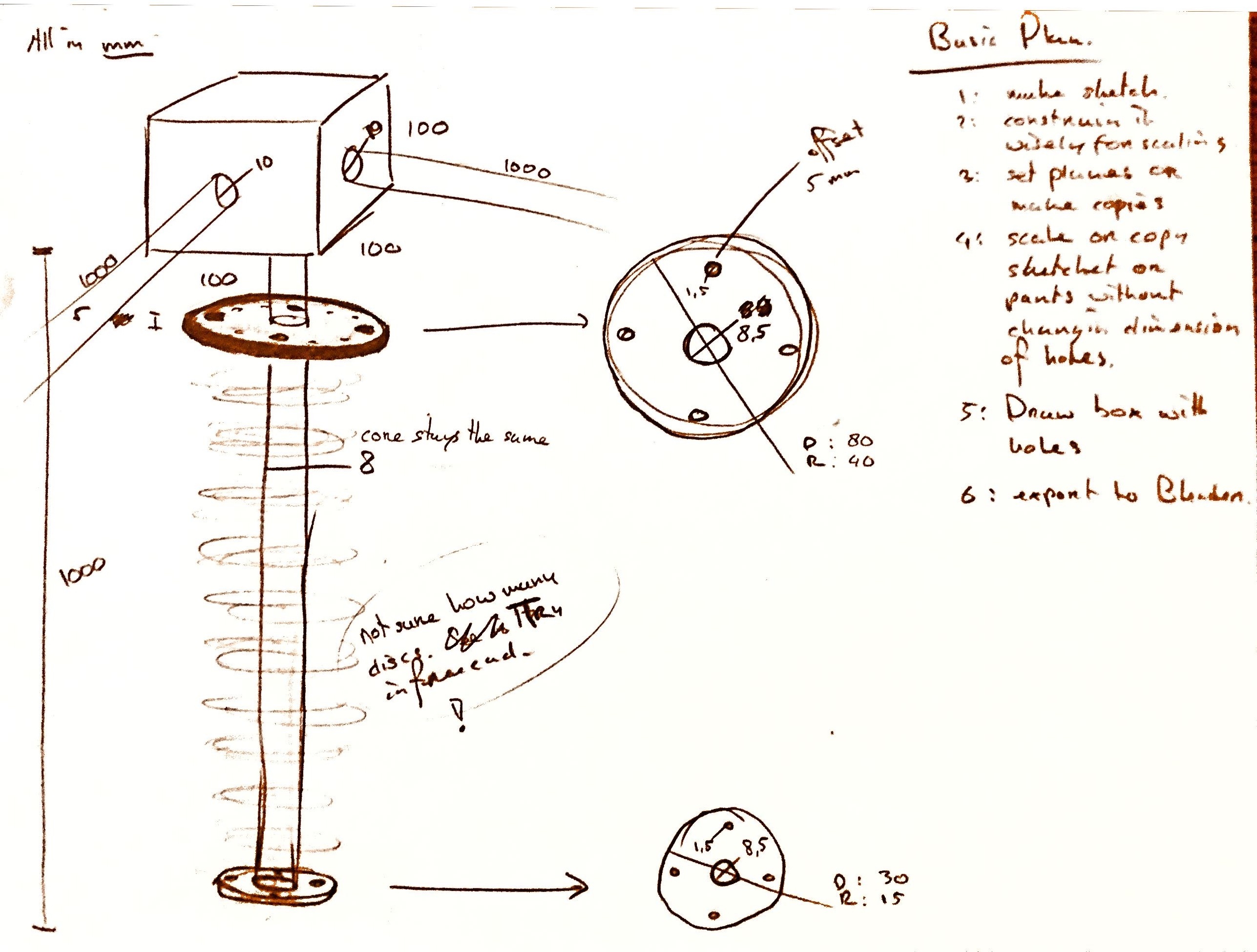
I like animatronics. A while ago I decided to work on an octopus tentacle and I started with these sketches. The first idea was to make a X/Y axes but due to the lack of time I eventually chose for Quintins Bolsee linear Beehive.
On the sketch on the right hand side I came up with the idea to devide the arm in two stages. So you could move both parts seperately.
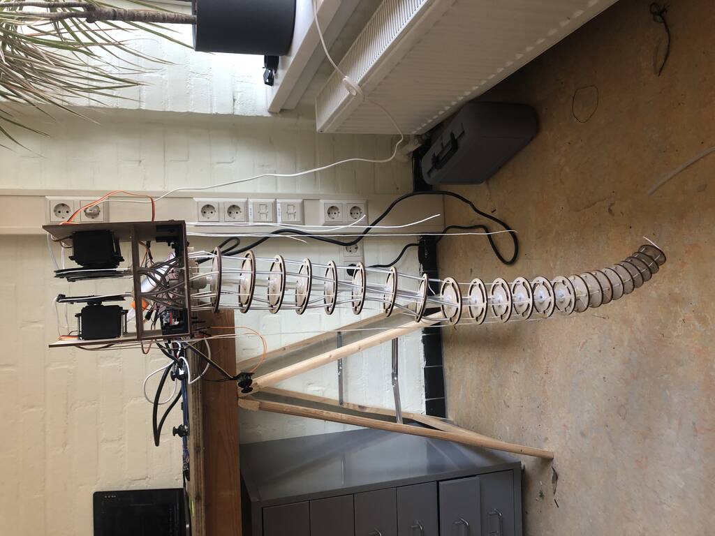
This was the first prototype. It already worked pretty nice.
These were the parts I used:
- joystick
- Arduino Uno
- Pulleys I made out MDF. (I would print or lasercut them next time)
- 2 mg996R servos
Code
#include <Servo.h>

Servo servo1;
Servo servo2;

int joyX1 = A0;
int joyY1 = A1;

int joyVal;

void setup ()
{
  servo1.attach(6);
  servo2.attach(5);
}
void loop()
{
  joyVal = analogRead(joyX1);
  joyVal = map (joyVal, 0, 1023, 0, 180);
  servo1.write(joyVal);
  joyVal = analogRead(joyY1);
  joyVal = map (joyVal, 0, 1023, 0, 180);
  servo2.write(joyVal);

  joyVal = analogRead(joyX2);
  joyVal = map (joyVal, 0, 1023, 0, 180);
  servo3.write(joyVal);
  joyVal = analogRead(joyY2);
  joyVal = map (joyVal, 0, 1023, 0, 180);
  servo4.write(joyVal);
  delay(15);
}
From seeing the first prototype work I got loads of ideas to improve the first model. I started sketching but decided to devide the model into a couple of main pieces. I expect that Octo will have to go through a lot of stages before I’ll be happy with it. That makes a modular design the most important demand for this project.
Octo (from top to down)
- Electronics
- X/Y / linear -Axes
- Servo housing
- Pulleys
- Tentacle / Vertabrea
- Discs
- Flexible core
- Inflatable gripper
Working principle
I thought that my second prototype wouldn’t take me to long. It took me a couple of days eventually. During the making process of the prototype I wanted to make a lot of changes. But it was hard to adapt because my design weren’t parametric and I used screws and hotglue. If I wanted to make a model that’s easy to adapt all of the part must be easy to take apart. This will save me a lot of time and frustration in the end.
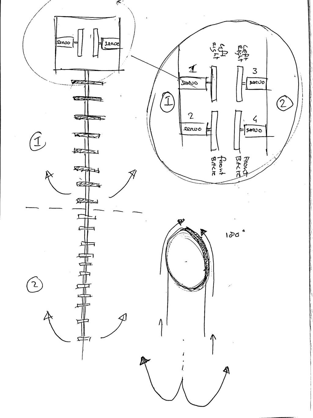
If my you don’t understand the principle yet, hopefuly this prototype will elucidate the working principle of Octo.
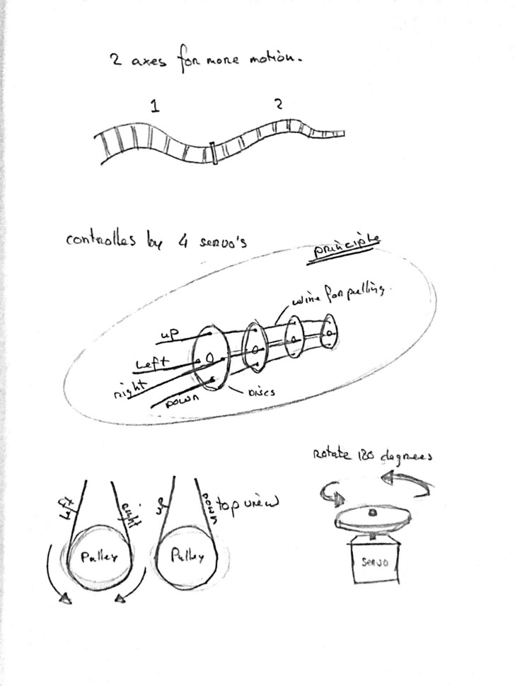
The vertabrea has 2 main parts. Each part is connected to 2 servos. Each servo represents the 2 opposite directions of each other.
These video give a clear overview how these arm move and work.
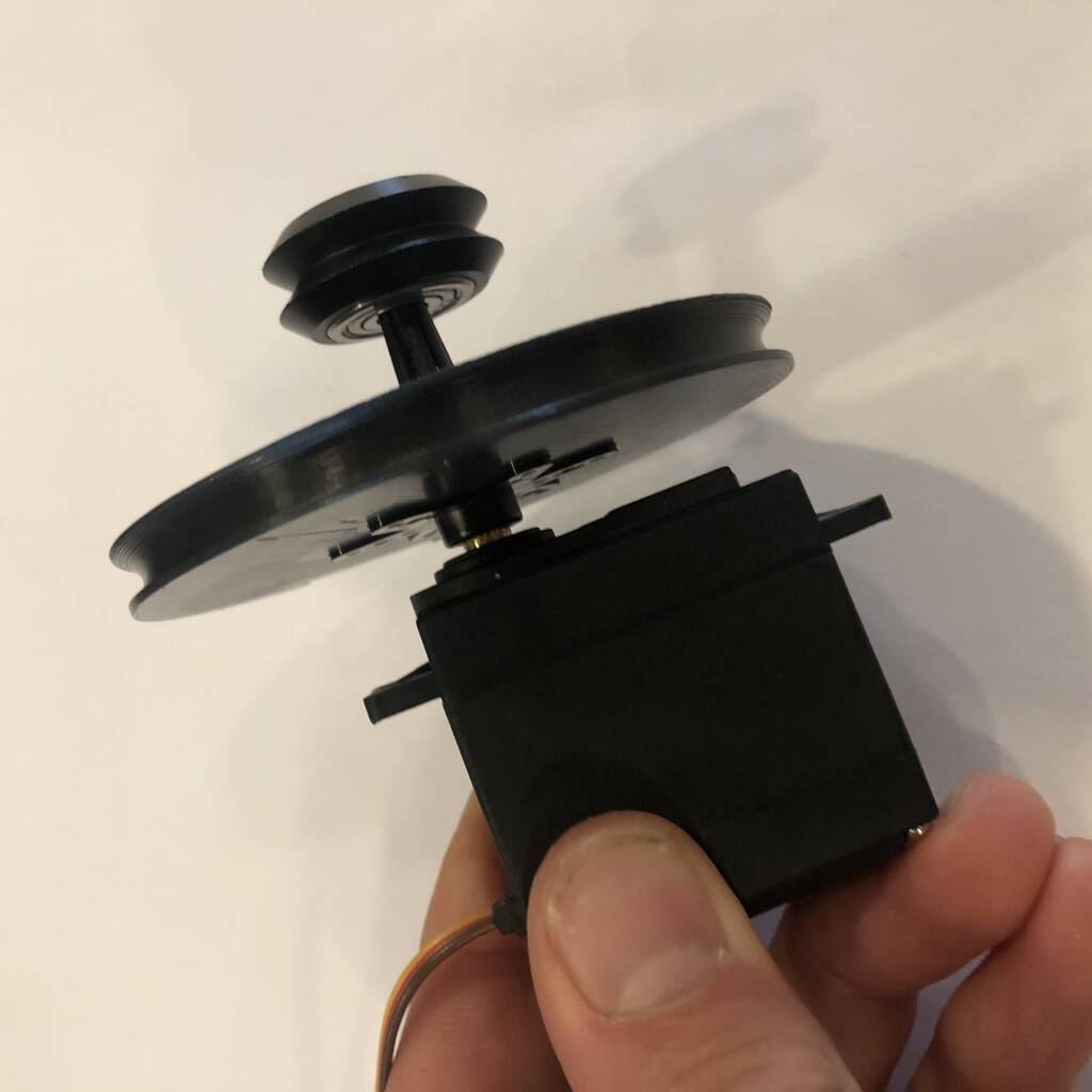
Pulleys
The pulleys should be attached to the servos. When buying a servo you get serveral ‘horns’ to mount on the motor. I integrated the 6 arm horn in my pulley design.

I used [this] 6arm servo arm for the MG966R and applied the sketch in my design. Since it’s not a fusion model you can ‘project’ the mesh in to a new sketch.
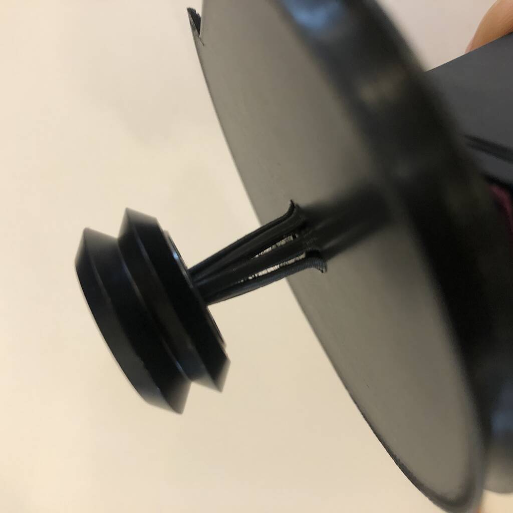
First I thought of making a tube at the end of the pulley that I could fit into a ball bearing for extra stability and to prevent the servos of consuming unnessary power. Unfortunately the tubes broke easily and finaly I decided to make a total different design.
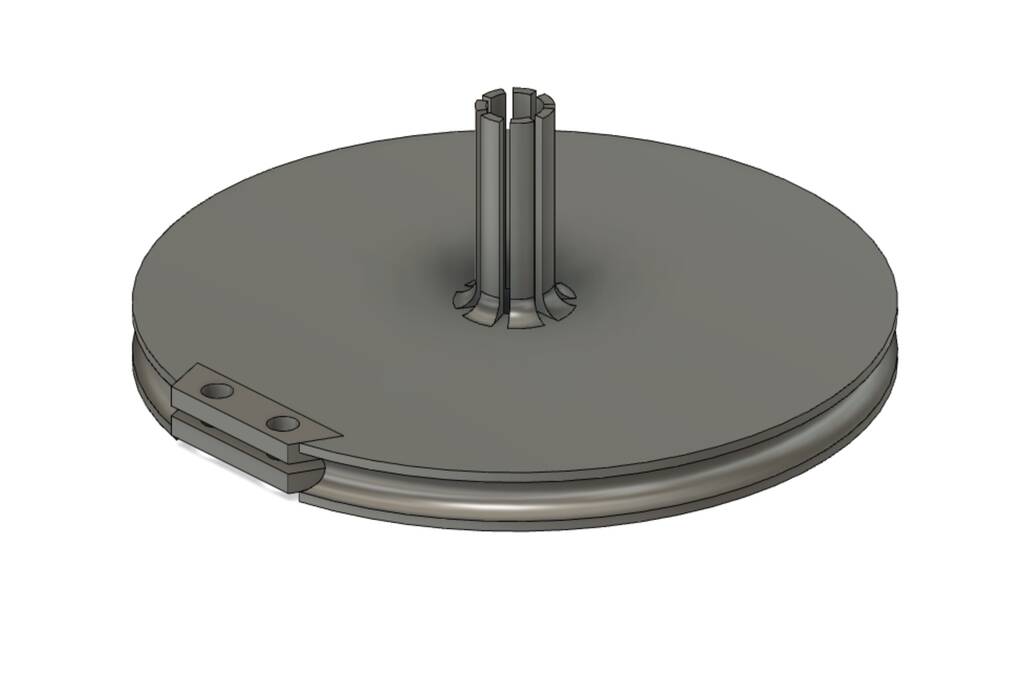
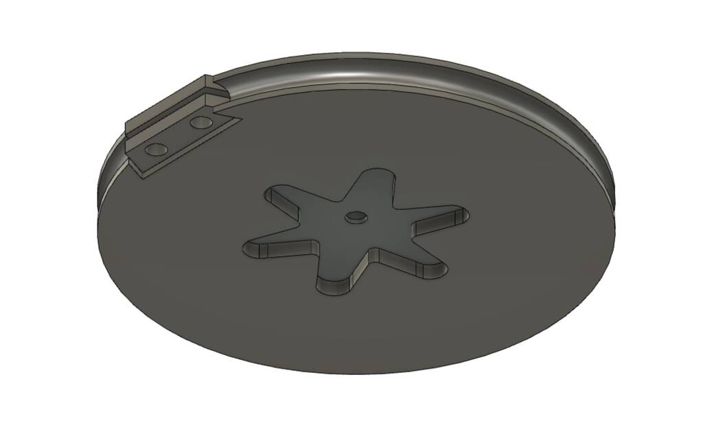
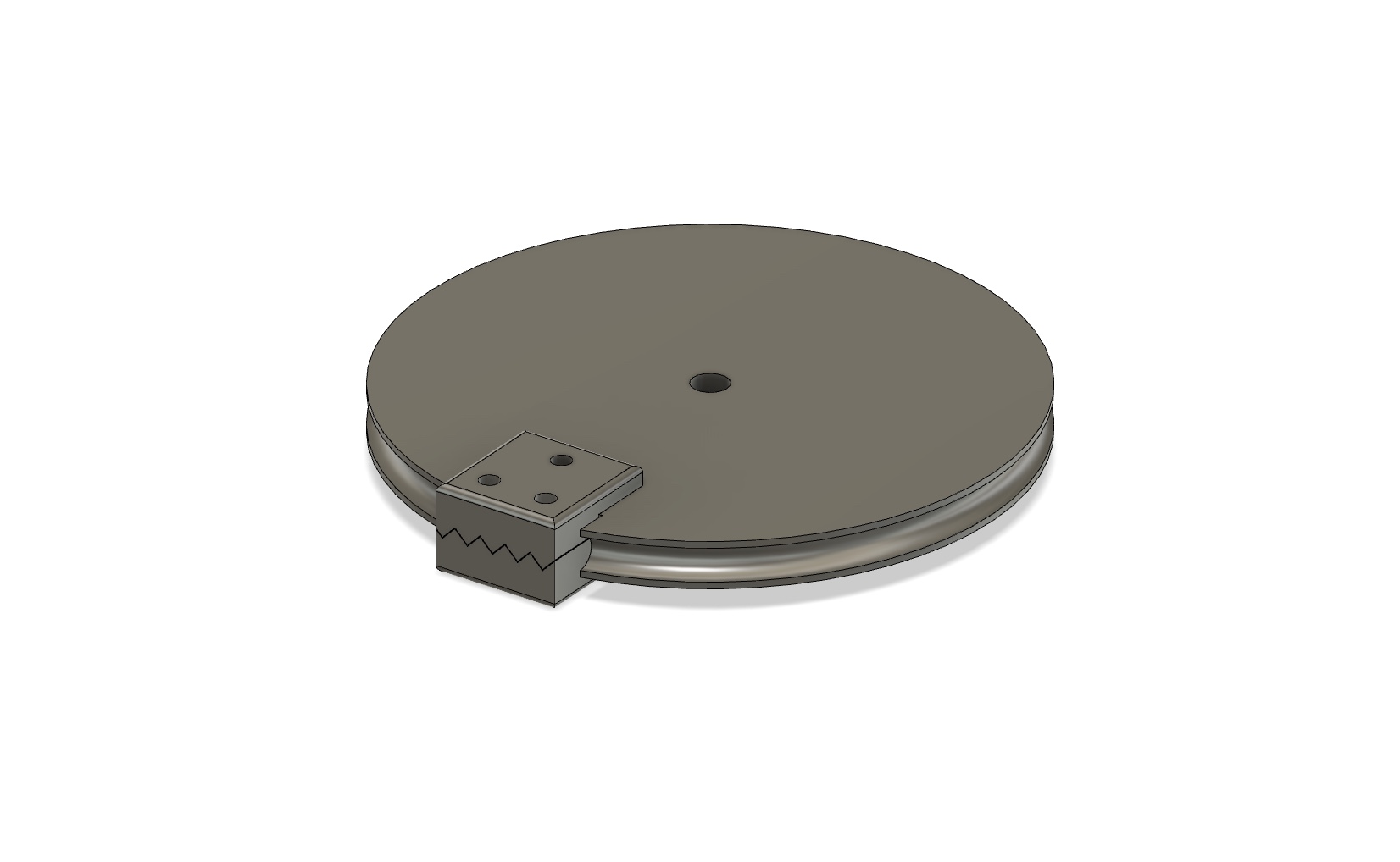
I eventually designed this simple parametric pulley. You can find the fusion file at the end of this page in the ‘File’ section.
Tentacle / Vertabrea
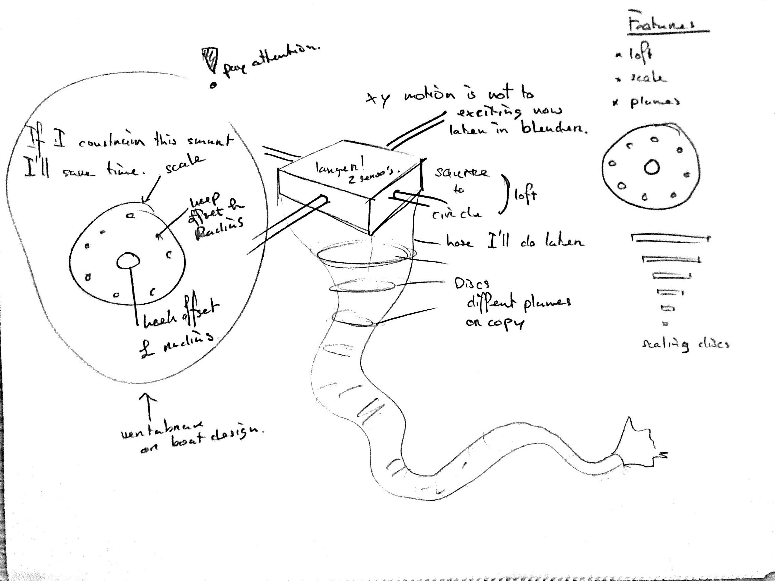
The vertabrae is the most complex part of Octo. The vertabrea exists out of different sub-parts. The flexible core, the discs, the cablehousings and the thread - together they form the vertabrea. The vertabrea could easily be transfromed into a tentacle by covering it with a textile sock for example.
I made a sketch that hopefully will help to understand how it works.
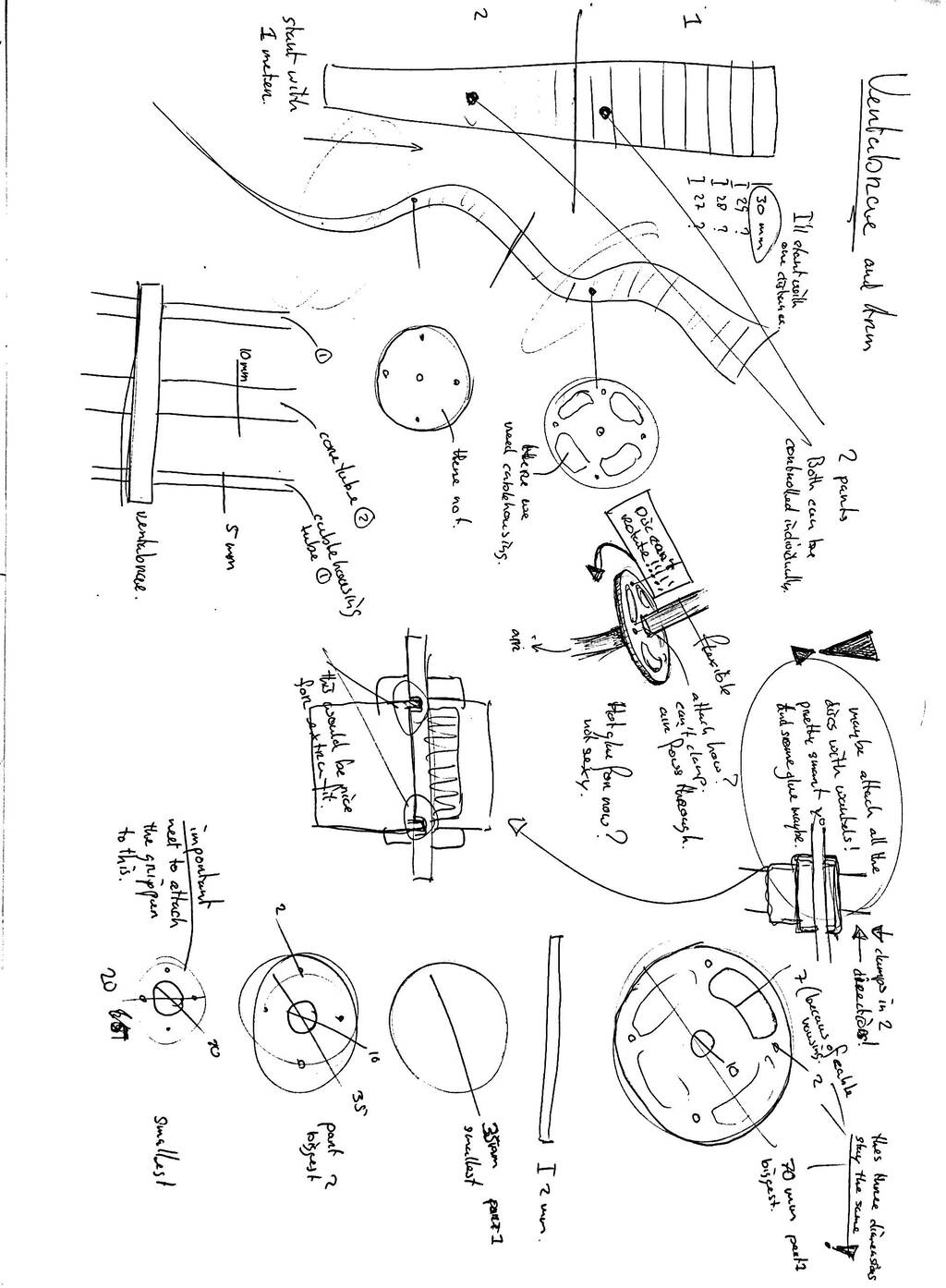
The vertabrea has 2 parts that can be controlled seperate from each other. I used cablehousing in the top part of the vertabrea. So when the servos pull the threads that are attached to the bottom part of the tentacle they only move this part because they’ll slide through the cable housing in the top part.
I needed disc that I could attach but also could disassamble. Also the discs in the top part are different from the parts in the bottem part.
The core is super important. The core should be flexible but any flexibility in it’s rotation will prevent the vertabrea from moving in the wanted direction.
I’ll explain every part in detail below.
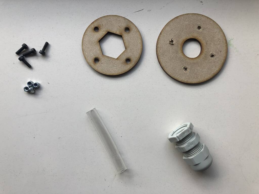
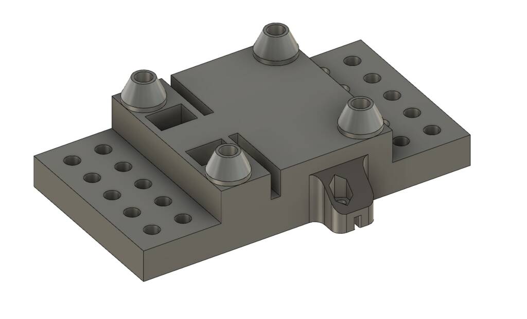
Discs
The discs should be easy to make. They should be round and have serveral holes to mount the thread, cable housing and the core through. Because I want to prototype and inprove the discs fast I thought that using the lasercutter and cheap but strong wood would do the trick for this part.

I made a very practical and parametric design for the vertabrea that you can find in the file section of this page. All of the dimensions are easy to change. You can export the sketch as a DXF.
I played a bit with all of the dimensions, some of them broke easily. It also depends on the material that you use.

The design of the disc is not the hard part its the way you connect the discs to the flexible core.
I wanted a non permanent joint for the disc to the core of the arm so that I’m able to adjust the space between the discs and to change the discs whenever is necessary.
My prototype tentacle was fixed with hot glue. This works fine but you can’t adjust the design. I also had an idea with set screws or nuts & bolds. But this takes ages and only works with 3d printed models.
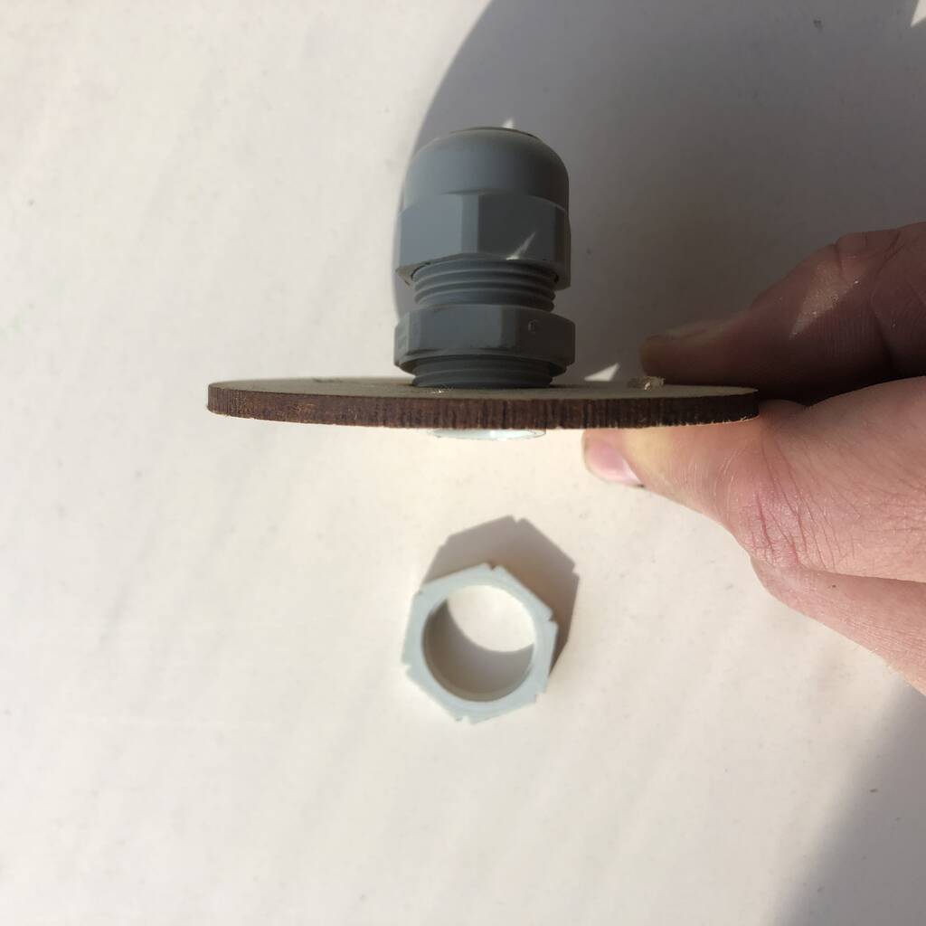
At my studio I went through a box and found some cable glands. This is exactly what I need. It’s super thight, the core stays hollow and it won’t rotate.
In this design I also integrated a second laser cutted layer, some bolts and nuts to prevent the cable gland from rotating. After some tests I found out that in this stage of the project this design is an overkill. But if I plan to work with more force this would be a good starting point.


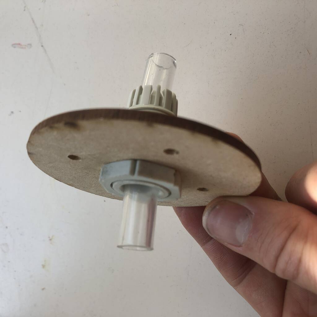
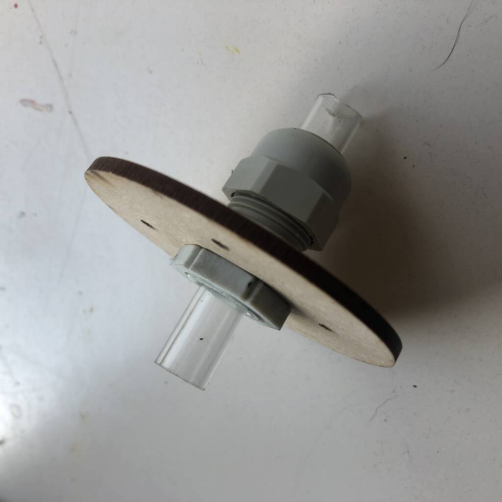
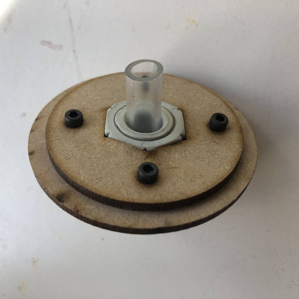
The result is pretty nice but the core that I’m using is too flexible. It rotates very easily. I did a little research flexible cores that you can read later on.

Flexible Core
The core is flexible. But unfortunately it also rotates.
Beehive axes
An X and Y axes is too much for now so I decided to work with the beehive axes from Quentin Bolsee. Quentin beehive axes is really easy and cheap to make. Everything is printed besides the ball bearings, fishing thread and a view bolts and nuts.
I changed a view things to the beehive axle frmo Quentin so that I could attach Octo to it.

Gripper
I made a gripper with ecoflex 00-30. I followed this tutorial to guide me through the process. Thanks Ben Finio.
Unfortunately the grippers exploded while testing because of an uneven thickness. Below you can see what they initially did. I hope I’ll give Octo some new inflatbles soon! If you’re interested in the my full research on inflatables please check out my page.
Electronics
I had a lot of ambitious ideas for the electronics for Octo and since I’m not to experienced working with electronics nothing went as I though it would go. I made several working principles but integrating all of them was quite hard. If there’s a catergory that really needs deserves an upgrade it’t the electronics part. I subdevided the folowing electronic categories.
- Micro controller
- Servos
- Stepper
- Dc pump and solenoid
- Controller
- Dabble esp32
Micro controller
I had a lot of difficulties working with the esp32-c3 Xiao Seeed boards. A lot of test I ran with an Arduino worked fine but when I tried it out with the Xiao boards I had complications that I did not have before. Also the eco-system regarding the xiao seeed board is not as extensive as for the esp32 wrover modules or other commercial esp boards. This did not help with debugging or copy paste working codes.
I worked with the following boards:
- Xiao esp32-c3 Seeed
- ESP32 diymore Wroom development boards, 2.4 GHz Dual Core, WLAN, WiFi, Bluetooth, CP2102 Chip
- ESP32 CAM
Tests that wouldn’t work on the Xiao boards did work on the esp32. But I have to admit that my coding knowledge is not something to be proud of. Most of the codes I uploaded were copied. I found it really difficult to see what was wrong. Again, for that reason I find it easier to work with commercially well know MCUs.
Servos Xiao esp32-c3
As I already mentioned controlling multiple servo’s on the Xiao esp32-c3 is a pain in the ass. It’s got something to do with Hertz that interfere with each other. On the digital pin I only manages to control the servos separately or 2/3 of them but 4 was unfortunately out of the question.
But eventually I found a library that works with multiple servos. The only drawback is that this library only work on the analog pins. Since the Xiao only has 4 analog pins I could only work with 2 servos and 1 joystick (a joystick needs 2 analog pins). The initial idea was to work with a wireless controller. So in theory it could work the only reason why I wouldn’t get it to work was time. So when I feel confident again. I’ll try to make it work with my intial idea.
These are the PCB design I made. These designs with the SVG files are also found in the file section. The board design is nothing fancy. Servos are relatively easy to work with. In future models I would go for two or even four 480OHM capacitors and place them close by the servos.

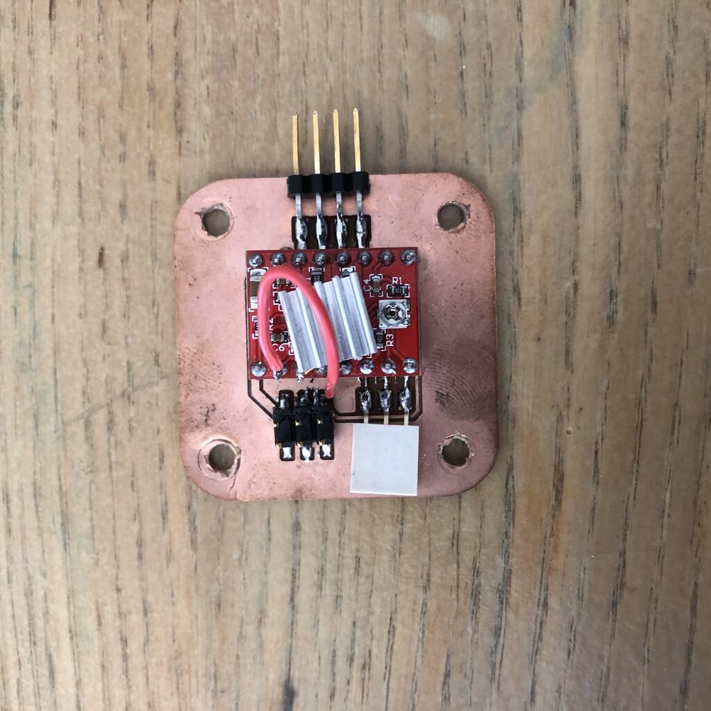
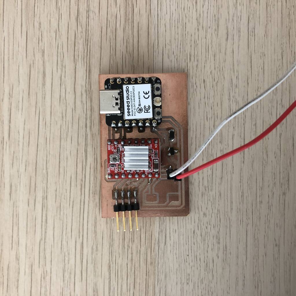
Stepper Xiao esp32-c3
For Quentins beehive axes I used a Nema 17 stepper motor with A4977 stepper driver. Also no fancy PCB but it works with a Xiao ESP32-C3 Seeed board.
This board can be simplified though the voltage regulator is not needed but do not forget to place flyback diode. Go to the Seeed page and walk yourself through the basics. It won’t take you long. If you want to change this design please remember that you don’t power the xiao board throuh its 3.3v pin. I even heard rumours on the world wide web that the Xiao board has an internal voltage devider and that you can power it with higher voltage.


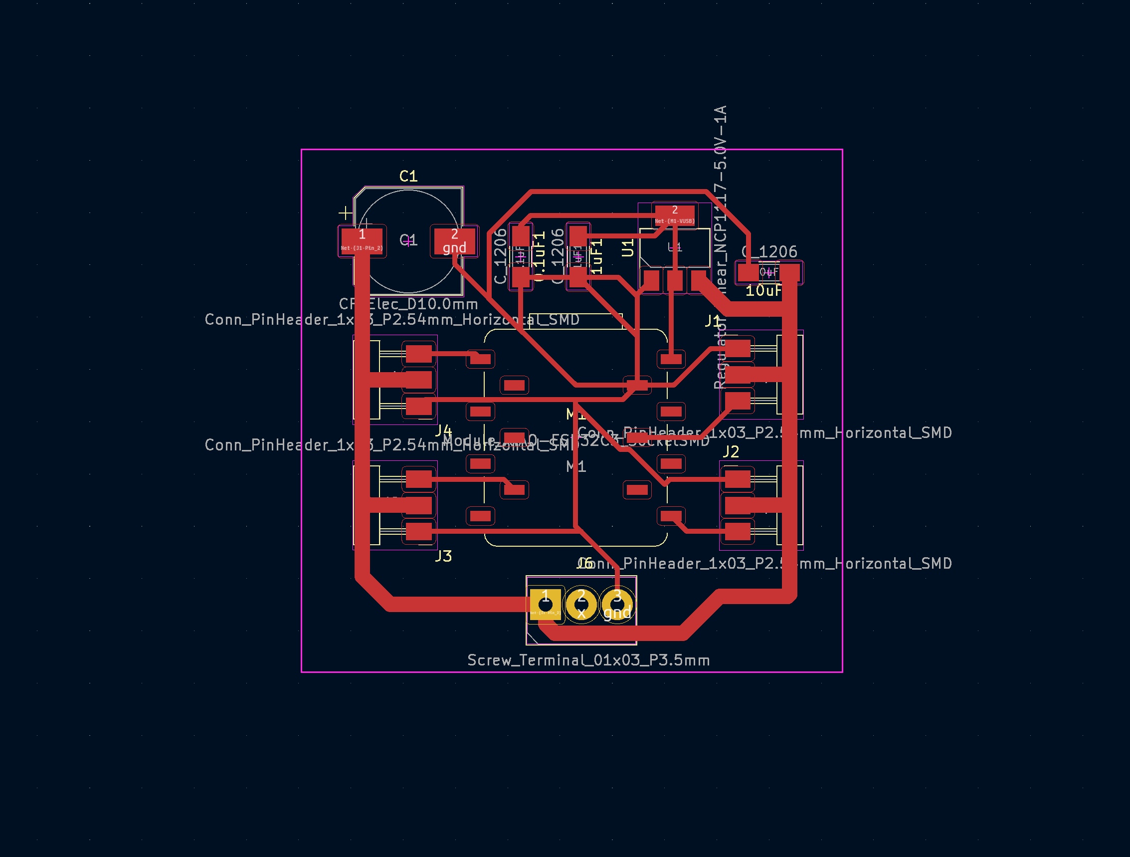
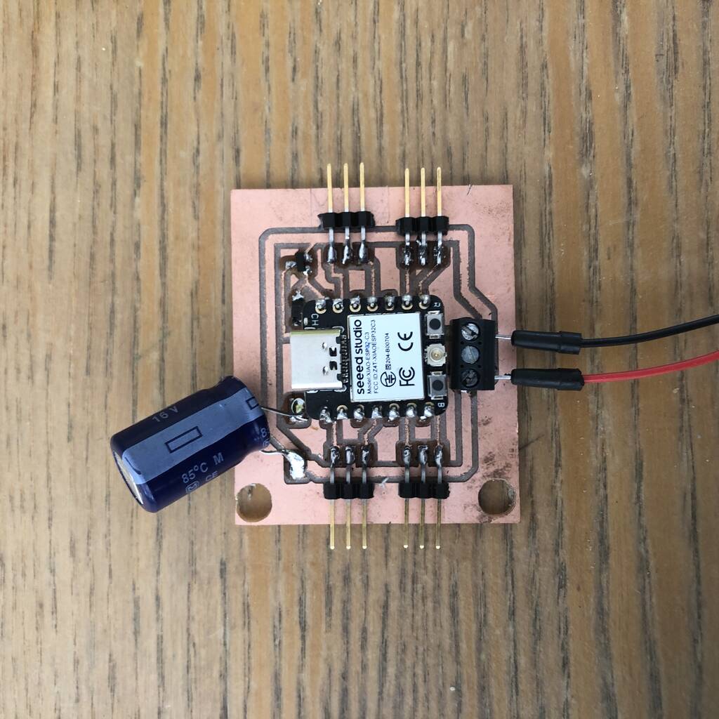
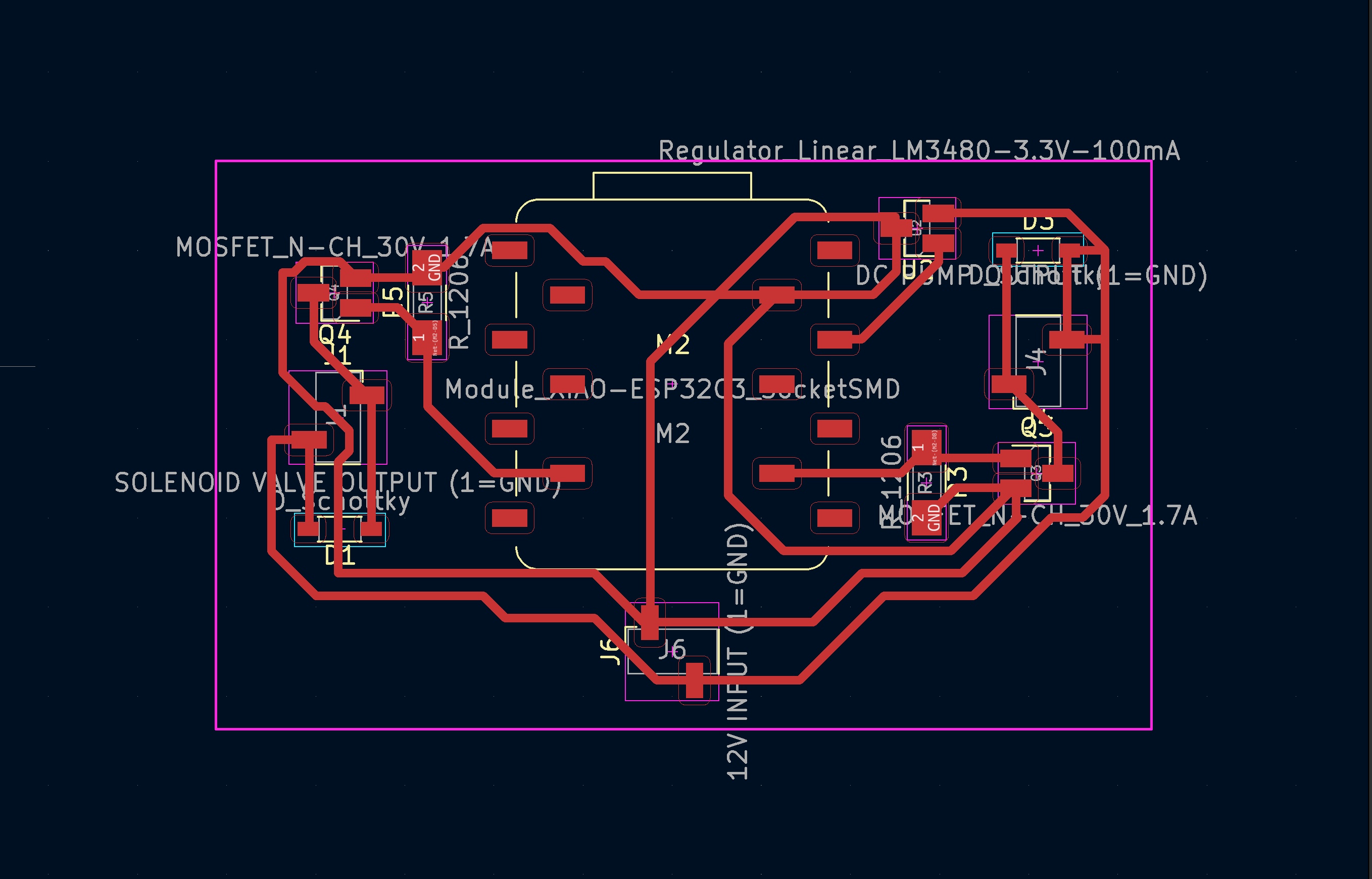
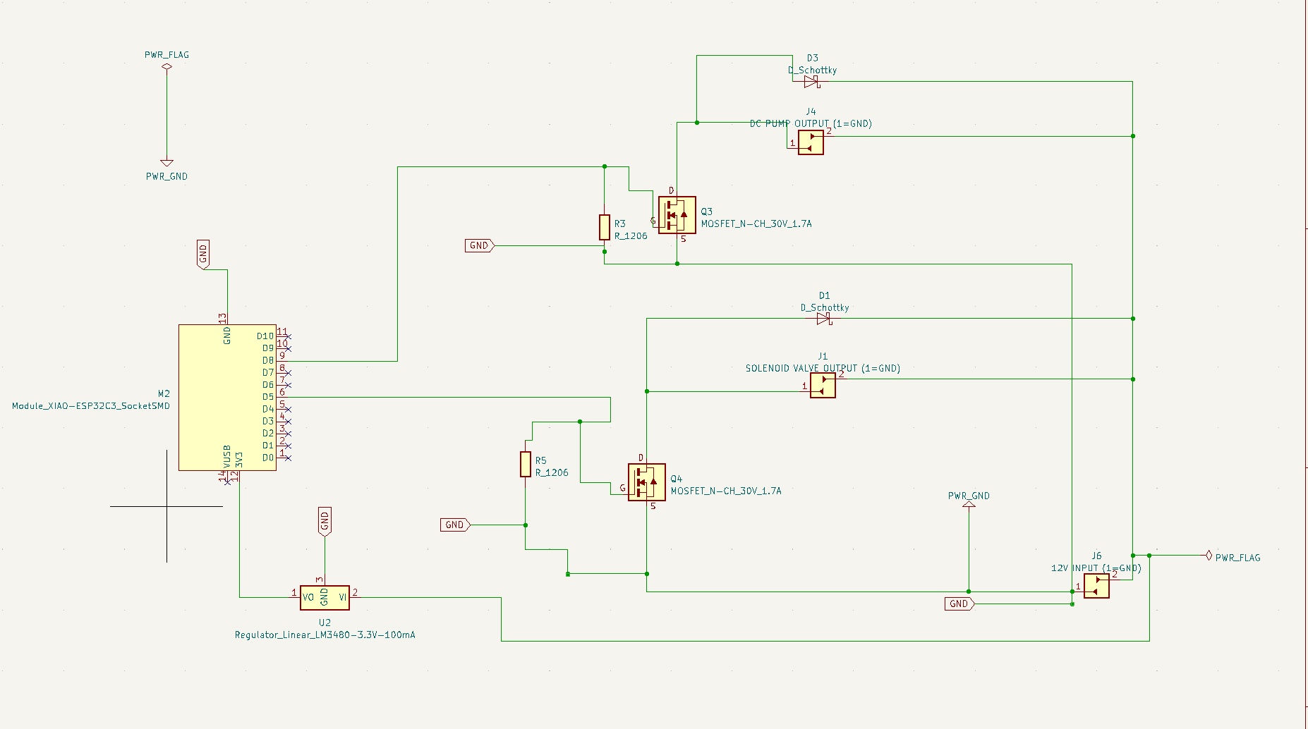
Dc pump and Solenoid Xiao esp32-c3
For the inflatable gripper I used a dc pump and a solenoid to inflate and deflate the gripper. The solenoid can be switched on and off (lets air through) through a MOSFET.
In my wildcard week I dit a lot of research on the DC pump and solenoid system.
These are the PCB designs. These design are waiting to get upgraded I didn’t got further then experimenting with them. They work though.
In my future design I don’t think I’ll be working with a Mosfet. I think I should take a look into dc motor drivers.

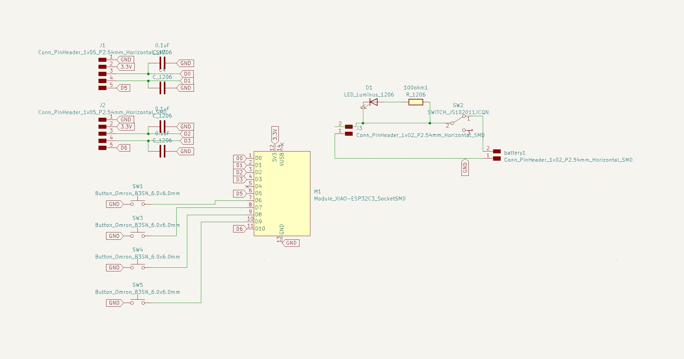
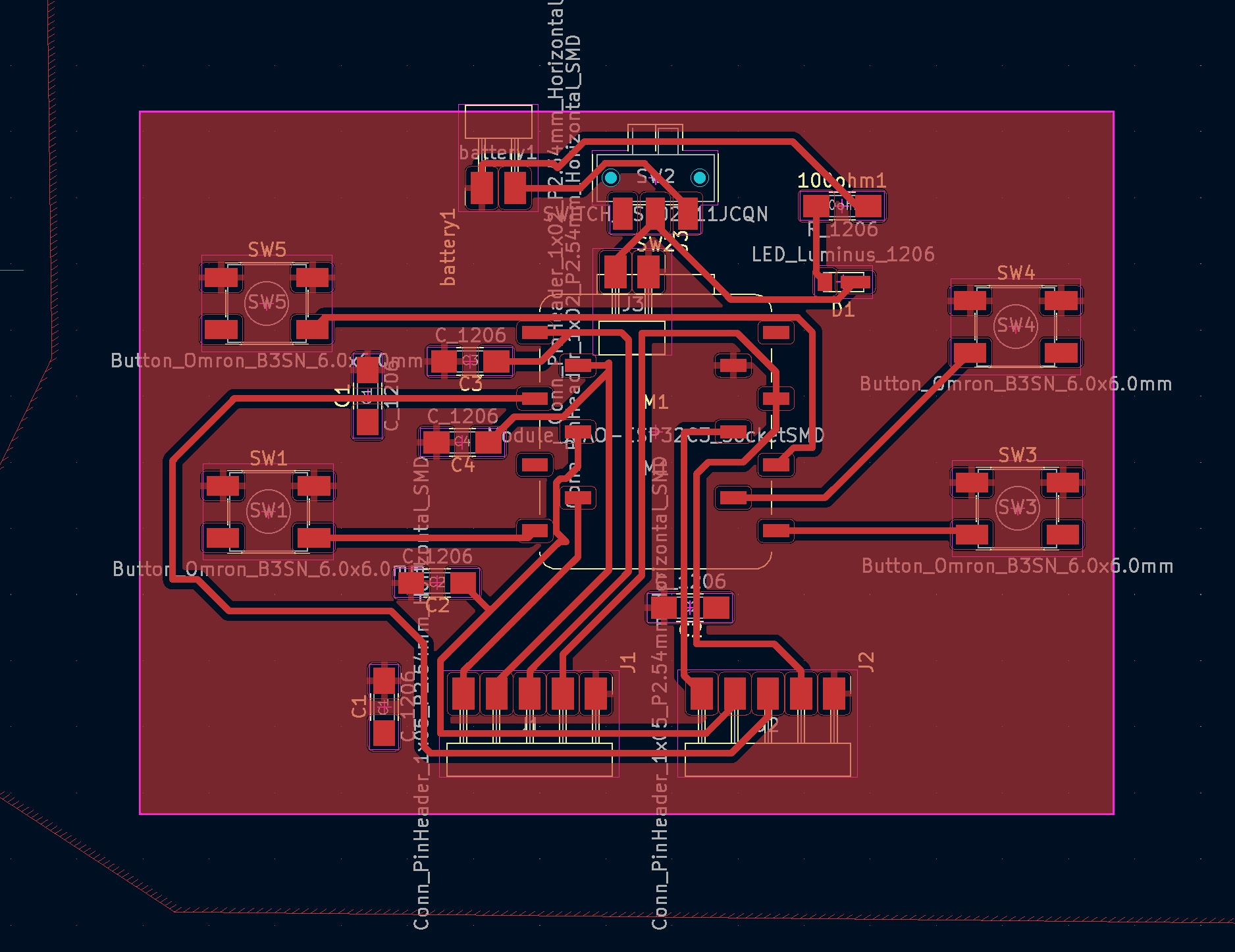
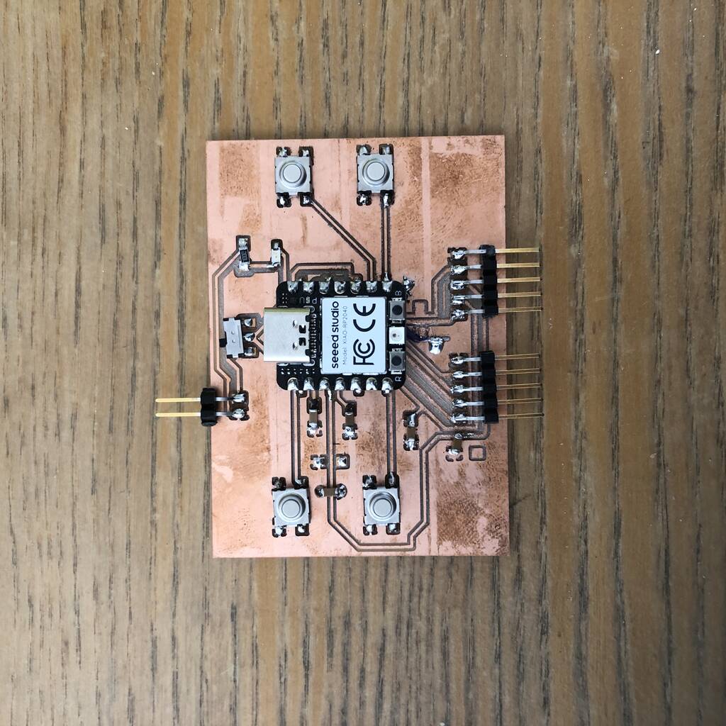
Controller
My initial idea was to make my own controller with an Xiao esp32-c3. But this was harder then I expected. A lot of things did not work. For example only 2 of the 4 buttons were working. I want to make another test and see if certain part work on a breadboard or an easy pcb design.
Dabble esp32
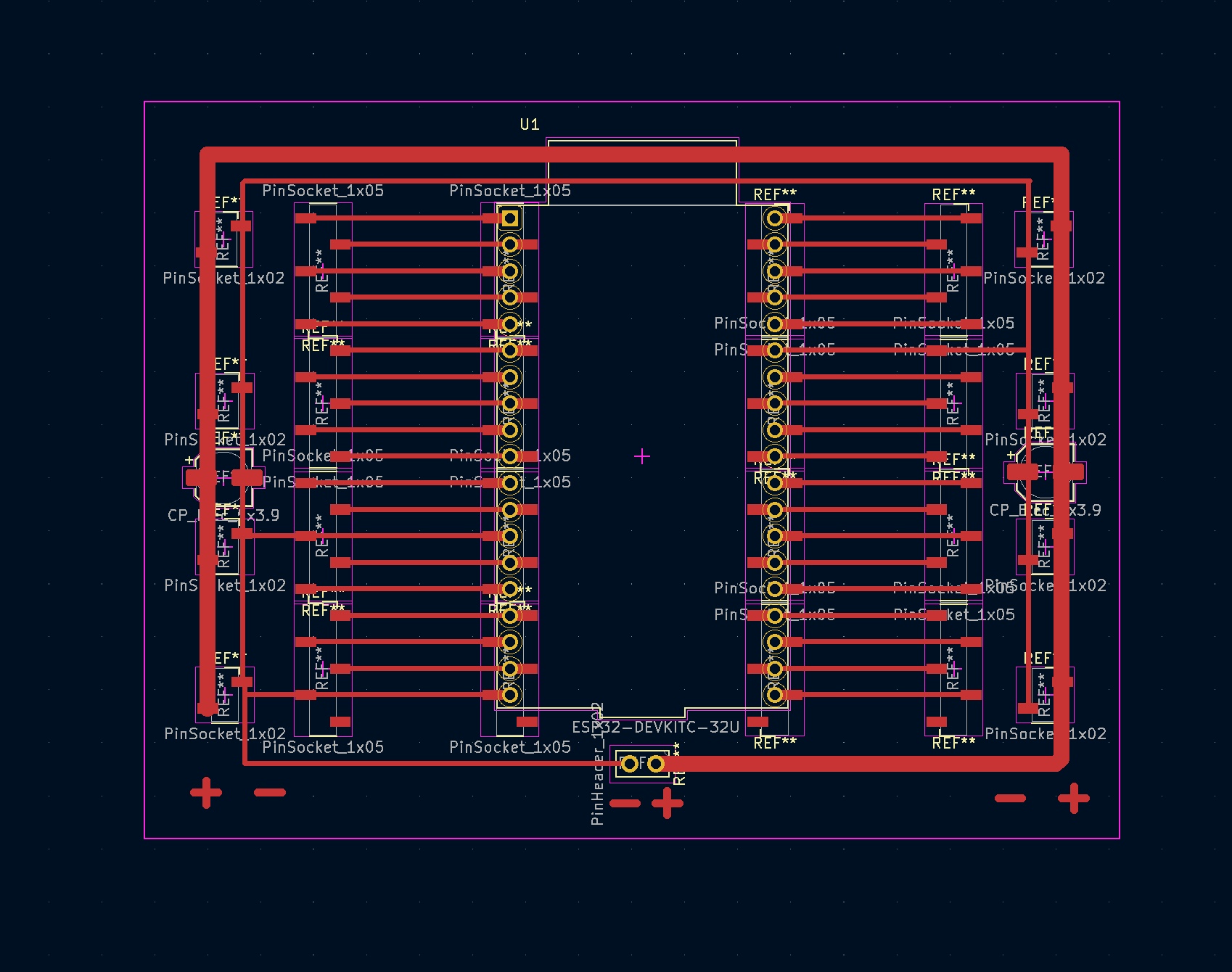
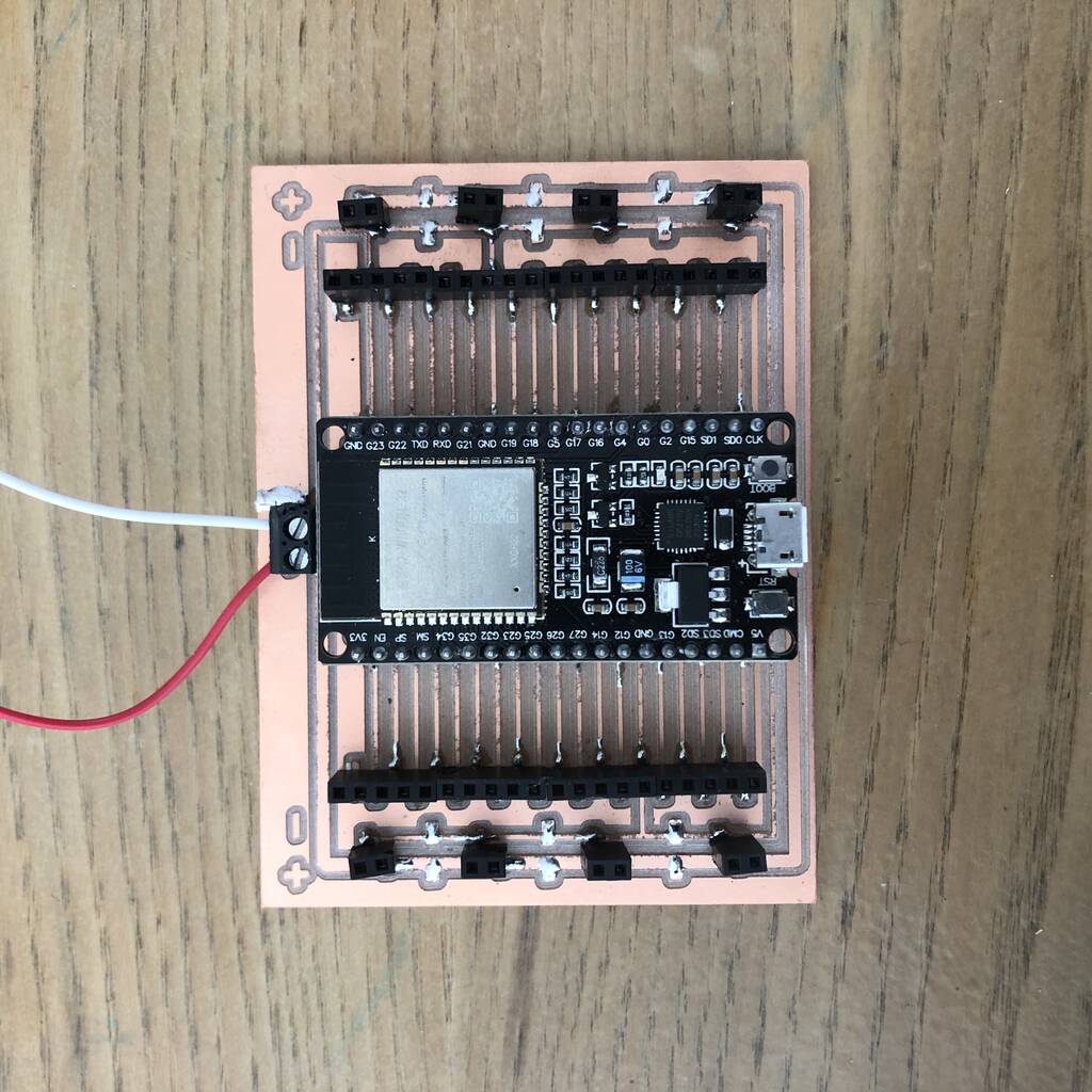
For my final PCB I made an enormous board for the esp32 diymore wroom development board. I wanted to make sure I could work with all the pins. I would see this is a very verstetile breakout board. Not a board that I’m really proud of but it works.
I made the PCB wihout the schetmatics because I could’t find the correct footprint for the diymore pinlayout. You got to pay a price when you buy remakes that aren’t to famous.
Set-up
This was the electronic setup for my finalproject. I didn’t had enough time to integrate everything as I initially wanted it.
From right to left: - powersource - esp32 develepment board - esp32-c3 stepper board


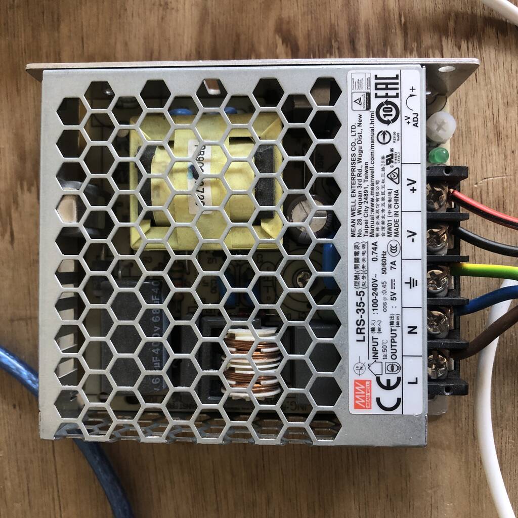
Power source
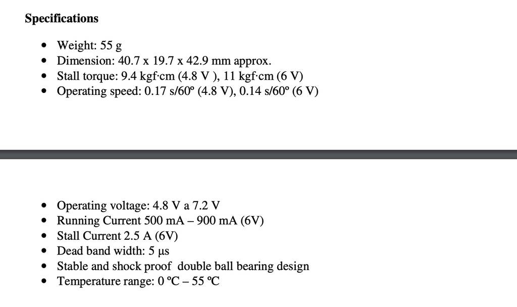
It’s important to use the correct power source. These servos eat a lot of current. I used a 5V 7A direct current external power source.
The stall current of the mg966r is 2.5 Amps at 6V. 7A / 4 servos = 1.75A. A 6V 10A power source would be perfect. But this will do the job for now.
BOM
This is a list of the you’ve to buy. Little thing like bold and nuts, filament ant wood for example I did not take into account.
| What | link | Amount | Cost | Datasheet |
|---|---|---|---|---|
| Solenoid | solenoid | 1x | €10 | |
| Dc airpump | dc airpump | 1x | €8 | |
| Aquarium tube connectors | Aquarium tube connectors | 1 pack | €5 | |
| mg996r servo motors | mg996r | 4x | €25 | |
| External power source | power source | 1x | €12 | |
| Cable glands | cable gland pg11 | 20x | €20 | |
| Flexible core | flexible core | 1.5 m | €5 | |
| Esp32 | esp32 | 1x | €8 | |
| Stepper motor | Nema 17 | 1x | €13 | |
| Fishing thread | fishing thread | 1x | €8 |
Total = € 120,-
Code
First I wanted to control Octo with a wireless controller through the ESPNOW communication protocol. But it was to difficult for me. I did a lot of experiments that you can see in my previous weeks. But I finaly decided, due to the lack of time, to work with a commercial app called dabble.
I tweaked a code that I found and I was able to control Octo with 1 degree steps. I did not succeed in controlling the stepper with the dabble app.
It workes but there are often bluetooth connection problems.
#define CUSTOM_SETTINGS
#define INCLUDE_GAMEPAD_MODULE
#include <DabbleESP32.h>
#include <Arduino.h>
#include <ESP32Servo.h> //<Servo.h>

//create servo object to control a servo
Servo leftRight;
Servo upDown;
Servo backForth;
Servo forthBack;

//combo gpio 27,21, 18 works.
#define leftRightPin 27 //27
#define upDownPin 21 //26
#define backForthPin 18 //25
#define forthBackPin 26
#define LEDpin 20

//initial angle  for servo
int angle = 90;
int angleStep = 1;


// Include the AccelStepper Library
#include <AccelStepper.h>

// Define pin connections (27, 26, 25 also works)
const int dirPin1 = 14; //16 //32; //27;
const int stepPin1 = 13; //17// 35; //26;
const int sleepResetPin1 = 12; //19 //34; //25;

// Define motor interface type
#define motorInterfaceType 1

// Creates an instance
AccelStepper myStepper1(motorInterfaceType, stepPin1, dirPin1);


void setup() {
  leftRight.attach(leftRightPin);
  upDown.attach(upDownPin);
  backForth.attach(backForthPin);
  forthBack.attach(forthBackPin);
  ///pinMode(LEDpin, OUTPUT);

  Serial.begin(115200);
  Dabble.begin("ESP32ServoController");

  // STEPPER
  // set the maximum speed, acceleration factor,
  // initial speed and the target position
  myStepper1.setMaxSpeed(1000);
  myStepper1.setAcceleration(50);
  myStepper1.setSpeed(200);
  myStepper1.moveTo(550);

  pinMode(sleepResetPin1, HIGH);

  delay(1);


}

void loop() {
  Dabble.processInput();
  if (GamePad.isLeftPressed()) {
    angle = angle + angleStep;
    leftRight.write(angle);
    digitalWrite(LEDpin, HIGH);
    delay(20);
  }
  else if (GamePad.isRightPressed()) {
    angle = angle - angleStep;
    leftRight.write(angle);
    digitalWrite(LEDpin, HIGH);
    delay(20);
  }
  else if (GamePad.isUpPressed()) {
    angle = angle - angleStep;
    upDown.write(angle);
    digitalWrite(LEDpin, HIGH);
    delay(20);
  }
  else if (GamePad.isDownPressed()) {
    angle = angle + angleStep;
    upDown.write(angle);
    digitalWrite(LEDpin, HIGH);
    delay(20);
  }
  else if (GamePad.isTrianglePressed()) {
    angle = angle + angleStep;
    backForth.write(angle);
    digitalWrite(LEDpin, HIGH);
    delay(20);
  }
  else if (GamePad.isCrossPressed()) {
    angle = angle - angleStep;
    backForth.write(angle);
    digitalWrite(LEDpin, HIGH);
    delay(20);
  }
    else if (GamePad.isSquarePressed()) {
    angle = angle + angleStep;
    forthBack.write(angle);
    digitalWrite(LEDpin, HIGH);
    delay(20);
  }
  else if (GamePad.isCirclePressed()) {
    angle = angle - angleStep;
    forthBack.write(angle);
    digitalWrite(LEDpin, HIGH);
    delay(20);

  }
  else if (GamePad.isStartPressed()) {
    leftRight.write(angle);
    delay(500);
    upDown.write(angle);
    delay(500);
    backForth.write(angle);
    delay(500);
    forthBack.write(angle);
    delay(500);
    digitalWrite(LEDpin, HIGH);
    delay(100);
    digitalWrite(LEDpin, LOW);
    delay(100);
    digitalWrite(LEDpin, HIGH);
    delay(100);
    digitalWrite(LEDpin, LOW);
    delay(100);
    digitalWrite(LEDpin, HIGH);
    delay(100);
    digitalWrite(LEDpin, LOW);
    delay(100);
    digitalWrite(LEDpin, HIGH);
    delay(100);
    digitalWrite(LEDpin, LOW);
  }
  else {
    digitalWrite(LEDpin, LOW);
  }


    // Change direction once the motor reaches target position
  if (myStepper1.distanceToGo() == 0)
    myStepper1.moveTo(-myStepper1.currentPosition());

  // Move the motor one step
  myStepper1.run();


}
Final project
Here you see I put everything together and that it works nicely
Here you can see my Final Project video and poster.
Conclusion
Octo is far from finished. But I think there’s a good start, thanks to its modular design, to evaluate Octo into better version step by step. It’s designed to disassemble. Nothing is joint permanently. All is connected with bolds and nuts, rotary joints or knots.
I have a little studio where I’ll install Octo and I can update him. If you’re intersted to help me grow Octo into a better version, please shut out.
I’ll hope to update soon.